Cisco Wireless Controller Configuration Guide, Release 8.3
Bias-Free Language
The documentation set for this product strives to use bias-free language. For the purposes of this documentation set, bias-free is defined as language that does not imply discrimination based on age, disability, gender, racial identity, ethnic identity, sexual orientation, socioeconomic status, and intersectionality. Exceptions may be present in the documentation due to language that is hardcoded in the user interfaces of the product software, language used based on RFP documentation, or language that is used by a referenced third-party product. Learn more about how Cisco is using Inclusive Language.
- Updated:
- July 28, 2016
Chapter: DHCP
DHCP
DHCP Proxy
Information About Configuring DHCP Proxy
When DHCP proxy is enabled on the controller, the controller unicasts DHCP requests from the client to the configured servers. At least one DHCP server must be configured on either the interface associated with the WLAN or the WLAN itself.
 Note | DHCP proxy is enabled by default. |
Restrictions on Using DHCP Proxy
Configuring DHCP Proxy (GUI)
Configuring DHCP Proxy (GUI)
Configuring DHCP Proxy (CLI)
Configuring DHCP Proxy (CLI)
Configuring a DHCP Timeout (GUI)
| Step 1 | Choose Controller > Advanced > DHCP to open the DHCP Parameters page. |
| Step 2 | Select the DHCP Timeout (5 - 120 seconds) check box to enable a DHCP timeout on a global basis. Otherwise, unselect the check box. The valid range is 5 through 120 seconds. |
| Step 3 | Click Apply to commit your changes. |
| Step 4 | Click Save Configuration to save your changes. |
Configuring a DHCP Timeout (CLI)
DHCP Link Select and VPN Select
Prerequisites for Configuring DHCP Link Select and VPN Select
- The DHCP mode should be set to proxy.
- The DHCP external server should be configured.
- DHCP Option 82 must be enabled on the controller.
- The interface being configured should not be of type service or virtual.
- The relay source interface name should be a valid interface with IP address configured.
Note | Proxy mode is not supported for IPv6. |
Information About Configuring DHCP Link Select and VPN Select
In a wireless environment, when a client requests a DHCP address, specify to the DHCP server the subnet from which the IP address has to be assigned, using the giaddr field in the DHCP DISCOVER packet. You can also use the giaddr field to specify the address that the DHCP server can use to communicate with the DHCP relay agent (controller). It is difficult to determine that the controller IP address in the subnet is reachable from the DHCP server. Hence, there is a need to send link-selection information that is distinct from the controller-reachable address to the DHCP server. Using the DHCP link select (DHCP option 82, suboption 5) configured on the controller interface, the link selection information distinct from controller's reachable address is sent to the DHCP server.
In a large network's wireless environment, the Cisco Network Registrar (CNR) server, which is a DHCP server, has multiple pools created based on VPN IDs or VRF names. Using these pools, you can assign IP address to a client with the help of the DHCP VPN Select option (DHCP option 82 and suboption 151). When you enable DHCP VPN Select (DHCP option 82 and suboption 151) on the controller interface, the controller sends the VPN ID or VRF name of the pool from which the IP address has to be assigned to the client. The DHCP VPN Select option enables easy-to-operate, shared usage of a centralized DHCP server, resulting in cost savings.
DHCP Link Select
Configure DHCP Link Select (DHCP option 82, suboption 5) on the management and dynamic interfaces of the controller. Before configuring DHCP Link Select on the controller interface, enable the DHCP proxy and DHCP option 82 on that interface.
When the Link Select option is enabled on the controller interface, suboption 5 is added to the packet with the IP address information that contains the desired subnet address for the corresponding client. The subnet address is the controller interface address mapped to the client VLAN interface. The DHCP server uses the subnet address to assign the IP address to the DHCP client.
DHCP VPN Select
Configure DHCP VPN Select (DHCP option 82, suboption 151) on the management and dynamic interfaces of the controller. Before configuring DHCP VPN Select on the controller interface, enable the DHCP proxy and DHCP option 82 on that interface.
You can configure different VPN IDs or VRF names on the same controller or different controllers using the VPN Select feature configured on the controller interface. Configuring the VPN Select feature, results in the DHCP server VPN pools having nonoverlapping addresses.
You must add VSS Control suboption 152 every time VSS suboption 151 is sent to the DHCP server. If the DHCP server understands and acts on VSS suboption 151, VSS Control suboption 152 is removed from the DHCP acknowledgment. If the DHCP server copies back VSS Control suboption 152 in the DHCP acknowledgment, it means that the DHCP server does not have the required support for the VSS suboption.
Mobility Considerations
Same Subnet
VPN ID or VRF name mapping to a WLAN should be the same on all the controllers in a mobility group. For example, if WLAN1 interface maps to VPN ID 1 and WLAN2 interface maps to VPN ID 2 maps on WLC A, then WLC B should also have WLAN1 interface mapping to VPN ID 1 and WLAN2 interface mapping to VPN ID 2. This way, when client L2 roams to another WLC, the roamed WLC's DHCP configuration will ensure that the client is assigned an address from the same VPN.
Different subnet mobility
With L3 mobility, all the DHCP DISCOVER packets are sent to the anchor and the assignment of the original VPN is ensured.
Auto anchor mobility
All the DHCP DISCOVER packets are sent to the anchor and the assignment of the original VPN is ensured.
Configuring DHCP Link Select and VPN Select (CLI)
| Step 1 | Configure the dynamic interface using the following commands: |
| Step 2 | Configure DHCP option 82 on a dynamic interface using the following commands: |
| Step 3 | Configure Link
Select suboption 5 on a dynamic interface using the following commands:
|
| Step 4 | Configure VPN
Select suboption 151 on a dynamic interface using the following commands:
|
| Step 5 | Configure Link
Select suboption 5 on a management interface using the following commands:
|
| Step 6 | Configure VPN
Select suboption 151 on a management interface using the following commands:
|
| Step 7 | Save the configuration using the following command: save config |
| Step 8 | To view the details of the Link Select settings or the VPN Select interface settings, enter the following command: show interface detailed |
Configuring DHCP Link Select and VPN Select (GUI)
| Step 1 | Choose . |
| Step 2 | Select the interface you want to configure the DHCP option-82 link select or VPN select. You can configure the DHCP option-82 link select on the management or dynamic interfaces in the controller. The Interfaces > Edit page is displayed with DHCP information on the primary and secondary DHCP servers configured in the controller. If the primary and secondary servers are not listed, you must enter values for the IP address of the DHCP servers in the text boxes displayed in this window. |
| Step 3 | Select the Enable DHCP Option 82 check box to enable DHCP option 82 on the interface. |
| Step 4 | Select the Enable DHCP Option 82-Link Select check box to enable link select on the interface. |
| Step 5 | From the Link Select relay source drop-down list, choose management or dynamic to enable link select on the interface. When link select is enabled, you can select any interface as relay source management and dynamic interface configured on the controller. |
| Step 6 | Select the Enable DHCP Option 82-VPN Select check box to enable VPN select on the management interface. When VPN select is enabled, you can configure either VRF Name or VPN ID. If you try to configure both the options, you are prompted with an error message. |
| Step 7 | In the VPN Select - VRF name text box, enter the VRF name. |
| Step 8 | In the VPN Select - VPN ID text box, enter the VPN ID. VPN ID should be provided in format of xxxxxx:xxxxxxxx. |
| Step 9 | Click Apply to save the configuration. |
DHCP Option 82
Information About DHCP Option 82
DHCP option 82 provides additional security when DHCP is used to allocate network addresses. It enables the controller to act as a DHCP relay agent to prevent DHCP client requests from untrusted sources. You can configure the controller to add option 82 information to DHCP requests from clients before forwarding the requests to the DHCP server.
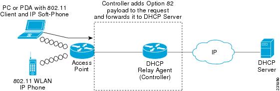
The access point forwards all DHCP requests from a client to the controller. The controller adds the DHCP option 82 payload and forwards the request to the DHCP server. The payload can contain the MAC address or the MAC address and SSID of the access point, depending on how you configure this option.
Note | Any DHCP packets that already include a relay agent option are dropped at the controller. |
For DHCP option 82 to operate correctly, DHCP proxy must be enabled.
Restrictions on DHCP Option 82
Configuring DHCP Option 82 (GUI)
| Step 1 | Choose to open the DHCP Parameters page. |
| Step 2 | Select the Enable DHCP Proxy check box to enable DHCP proxy. |
| Step 3 | Choose a DHCP Option 82 format from the drop-down list. You can choose either binary or ascii to specify the format of the DHCP option 82 payload. |
| Step 4 | Choose a DHCP Option 82 Remote ID field
format from the drop-down list to specify the format of the DHCP option 82
payload.
For more information about the options available, see the Controller Online Help. |
| Step 5 | Enter the DHCP timeout value in the DHCP Timeout field. The timeout value is globally applicable. You can specify the DHCP timeout value in range from 5 to 120 seconds. |
| Step 6 | Click Apply. |
| Step 7 | Click Save Configuration . |
What to Do Next
On the controller CLI, you can enable DHCP option 82 on the dynamic interface to which the WLAN is associated by entering this command:
config interface dhcp dynamic-interface interface-name option-82 enableConfiguring DHCP Option 82 (CLI)
Configure the format of the DHCP option 82 payload by entering one of these commands:
- config dhcp opt-82 remote-id ap_mac—Adds the radio MAC address of the access point to the DHCP option 82 payload.
- config dhcp opt-82 remote-id ap_mac:ssid—Adds the radio MAC address and SSID of the access point to the DHCP option 82 payload.
- config dhcp opt-82 remote-id ap-ethmac—Adds the Ethernet MAC address of the access point to the DHCP option 82 payload.
- config dhcp opt-82 remote-id apname:ssid—Adds the AP name and SSID of the access point to the DHCP option 82 payload.
- config dhcp opt-82 remote-id ap-group-name—Adds the AP group name to the DHCP option 82 payload.
- config dhcp opt-82 remote-id flex-group-name—Adds the FlexConnect group name to the DHCP option 82 payload.
- config dhcp opt-82 remote-id ap-location—Adds the AP location to the DHCP option 82 payload.
- config dhcp opt-82 remote-id apmac-vlan-id—Adds the radio MAC address of the access point and the VLAN ID to the DHCP option 82 payload.
- config dhcp opt-82 remote-id apname-vlan-id—Adds the AP name and its VLAN ID to the DHCP option 82 payload.
- config dhcp opt-82 remote-id ap-ethmac-ssid—Adds the Ethernet MAC address of the access point and the SSID to the DHCP option 82 payload.
Configure the format of the DHCP option 82 as binary or ASCII by entering this command:
config dhcp opt-82 format {binary |ascii}
Enable DHCP Option 82 on the dynamic interface to which the WLAN is associated by entering this command:
config interface dhcp dynamic-interface interface-name option-82 enable
See the status of DHCP option 82 on the dynamic interface by entering the show interface detailed dynamic-interface-namecommand.
Configuring DHCP Option 82 Insertion in Bridge Mode (CLI)
Configure DHCP Option 82 insertion in Bridge mode on the management interface by entering this command: config interface dhcp management option-82 bridge-mode-insertion {enable | disable}
Note
Enter the show interface detailed management command to see if DHCP Option 82 Bridge mode insertion is enabled or disabled on the management interface.
Configure DHCP Option 82 insertion in Bridge mode on the dynamic interface by entering this command: config interface dhcp dynamic-interface dynamic-interface-name option-82 bridge-mode-insertion {enable | disable}
Note
Enter the show interface detailed dynamic-interface-name command to see if DHCP Option 82 Bridge mode insertion is enabled or disabled on the dynamic interface.
Internal DHCP Server
Information About Internal DHCP Server
Controllers have built-in DHCP relay agents. However, when you desire network segments that do not have a separate DHCP server, the controllers can have built-in internal DHCP server that assign IP addresses and subnet masks to wireless clients. Typically, one controller can have one or more internal DHCP server that each provide a range of IP addresses.
Internal DHCP server are needed for internal DHCP to work. Once DHCP is defined on the controller, you can then point the primary DHCP server IP address on the management, AP-manager, and dynamic interfaces to the controller’s management interface.
Note | The controller has the ability to provide internal DHCP server. This feature is very limited and considered as convenience that is often used simple demonstration or proof-of-concept, for example in a lab environment. The best practice is NOT to use this feature in an enterprise production network. Read more about this at: http://www.cisco.com/c/en/us/support/docs/wireless/4400-series-wireless-lan-controllers/110865-dhcp-wlc.html#anc16 |
Restrictions on Configuring Internal DHCP Server
Configuring DHCP Scopes (GUI)
| Step 1 | Choose
Controller >
Internal DHCP
Server >
DHCP Scope to
open the
DHCP Scopes page.
This page lists any DHCP scopes that have already been configured.
| ||
| Step 2 | Click New to add a new DHCP scope. The DHCP Scope > New page appears. | ||
| Step 3 | In the Scope Name text box, enter a name for the new DHCP scope. | ||
| Step 4 | Click Apply. When the DHCP Scopes page reappears, click the name of the new scope. The DHCP Scope > Edit page appears. | ||
| Step 5 | In the
Pool Start Address text box, enter the
starting IP address in the range assigned to the clients.
| ||
| Step 6 | In the
Pool End Address text box, enter the ending IP
address in the range assigned to the clients.
| ||
| Step 7 | In the Network text box, enter the network served by this DHCP scope. This IP address is used by the management interface with Netmask applied, as configured on the Interfaces page. | ||
| Step 8 | In the Netmask text box, enter the subnet mask assigned to all wireless clients. | ||
| Step 9 | In the Lease Time text box, enter the amount of time (from 0 to 65536 seconds) that an IP address is granted to a client. | ||
| Step 10 | In the Default Routers text box, enter the IP address of the optional router connecting the controllers. Each router must include a DHCP forwarding agent, which allows a single controller to serve the clients of multiple controllers. | ||
| Step 11 | In the DNS Domain Name text box, enter the optional domain name system (DNS) domain name of this DHCP scope for use with one or more DNS servers. | ||
| Step 12 | In the DNS Servers text box, enter the IP address of the optional DNS server. Each DNS server must be able to update a client’s DNS entry to match the IP address assigned by this DHCP scope. | ||
| Step 13 | In the Netbios Name Servers text box, enter the IP address of the optional Microsoft Network Basic Input Output System (NetBIOS) name server, such as the Internet Naming Service (WINS) server. | ||
| Step 14 | From the Status drop-down list, choose Enabled to enable this DHCP scope or choose Disabled to disable it. | ||
| Step 15 | Save the configuration. | ||
| Step 16 | Choose DHCP Allocated Leases to see the remaining lease time for wireless clients. The DHCP Allocated Lease page appears, showing the MAC address, IP address, and remaining lease time for the wireless clients. |
Configuring DHCP Scopes (CLI)
| Step 1 | Create a new DHCP scope by entering this command: config dhcp create-scope scope
| ||
| Step 2 | Specify the starting and ending IP address in the range assigned to the clients by entering this command: config dhcp address-pool scope start end
| ||
| Step 3 | Specify the network served by this DHCP scope (the IP address used by the management interface with the Netmask applied) and the subnet mask assigned to all wireless clients by entering this command: | ||
| Step 4 | Specify the amount of time (from 0 to 65536 seconds) that an IP address is granted to a client by entering this command: | ||
| Step 5 | Specify the IP address of the optional router connecting the controllers by entering this command: config dhcp default-router scope router_1 [router_2] [router_3] Each router must include a DHCP forwarding agent, which allows a single controller to serve the clients of multiple controllers. | ||
| Step 6 | Specify the optional domain name system (DNS) domain name of this DHCP scope for use with one or more DNS servers by entering this command: | ||
| Step 7 | Specify the IP address of the optional DNS server(s) by entering this command: config dhcp dns-servers scope dns1 [dns2] [dns3] Each DNS server must be able to update a client’s DNS entry to match the IP address assigned by this DHCP scope | ||
| Step 8 | Specify the IP address of the optional Microsoft Network Basic Input Output System (NetBIOS) name server, such as the Internet Naming Service (WINS) server by entering this command: | ||
| Step 9 | Enable or disable this DHCP scope by entering this command: | ||
| Step 10 | Save your changes by entering this command: | ||
| Step 11 | See the list of configured DHCP scopes by entering this command:
Information similar to the following appears: Scope Name Enabled Address Range Scope 1 No 0.0.0.0 -> 0.0.0.0 Scope 2 No 0.0.0.0 -> 0.0.0.0 | ||
| Step 12 | Display the DHCP information for a particular scope by entering this command:
Information similar to the following appears: Enabled....................................... No Lease Time.................................... 0 Pool Start.................................... 0.0.0.0 Pool End...................................... 0.0.0.0 Network....................................... 0.0.0.0 Netmask....................................... 0.0.0.0 Default Routers............................... 0.0.0.0 0.0.0.0 0.0.0.0 DNS Domain.................................... DNS........................................... 0.0.0.0 0.0.0.0 0.0.0.0 Netbios Name Servers.......................... 0.0.0.0 0.0.0.0 0.0.0.0 |
DHCP for WLANs
Information About the Dynamic Host Configuration Protocol
You can configure WLANs to use the same or different Dynamic Host Configuration Protocol (DHCP) servers or no DHCP server. Two types of DHCP servers are available: internal and external.
Internal DHCP Servers
The controllers contain an internal DHCP server. This server is typically used in branch offices that do not already have a DHCP server. The wireless network generally contains a maximum of 10 access points or fewer, with the access points on the same IP subnet as the controller. The internal server provides DHCP addresses to wireless clients, direct-connect access points, and DHCP requests that are relayed from access points. Only lightweight access points are supported. When you want to use the internal DHCP server, you must set the management interface IP address of the controller as the DHCP server IP address.
DHCP option 43 is not supported on the internal server. Therefore, the access point must use an alternative method to locate the management interface IP address of the controller, such as local subnet broadcast, Domain Name System (DNS), or priming.
An internal DHCP server pool only serves the wireless clients of that controller, not clients of other controllers. Also, an internal DHCP server can serve only wireless clients, not wired clients.
When clients use the internal DHCP server of the controller, IP addresses are not preserved across reboots. As a result, multiple clients can be assigned with the same IP address. To resolve any IP address conflicts, clients must release their existing IP address and request a new one. Wired guest clients are always on a Layer 2 network connected to a local or foreign controller.
Note | DHCPv6 is not supported in the internal DHCP servers. |
External DHCP Servers
The operating system is designed to appear as a DHCP Relay to the network and as a DHCP server to clients with industry-standard external DHCP servers that support DHCP Relay, which means that each controller appears as a DHCP Relay agent to the DHCP server and as a DHCP server at the virtual IP address to wireless clients.
Because the controller captures the client IP address that is obtained from a DHCP server, it maintains the same IP address for that client during intra controller, inter controller, and inter-subnet client roaming.
Note | External DHCP servers can support DHCPv6. |
DHCP Assignments
You can configure DHCP on a per-interface or per-WLAN basis. We recommend that you use the primary DHCP server address that is assigned to a particular interface.
You can assign DHCP servers for individual interfaces. You can configure the management interface, AP-manager interface, and dynamic interface for a primary and secondary DHCP server, and you can configure the service-port interface to enable or disable DHCP servers. You can also define a DHCP server on a WLAN. In this case, the server overrides the DHCP server address on the interface assigned to the WLAN.
Security Considerations
For enhanced security, we recommend that you require all clients to obtain their IP addresses from a DHCP server. To enforce this requirement, you can configure all WLANs with a DHCP Addr. Assignment Required setting, which disallows client static IP addresses. If DHCP Addr. Assignment Required is selected, clients must obtain an IP address via DHCP. Any client with a static IP address is not allowed on the network. The controller monitors DHCP traffic because it acts as a DHCP proxy for the clients.
Note |
|
If slightly less security is tolerable, you can create WLANs with DHCP Addr. Assignment Required disabled. Clients then have the option of using a static IP address or obtaining an IP address from a designated DHCP server.
Note | DHCP Addr. Assignment Required is not supported for wired guest LANs. |
You can create separate WLANs with DHCP Addr. Assignment Required configured as disabled. This is applicable only if DHCP proxy is enabled for the controller. You must not define the primary/secondary configuration DHCP server you should disable the DHCP proxy. These WLANs drop all DHCP requests and force clients to use a static IP address. These WLANs do not support management over wireless connections.
Restrictions for Configuring DHCP for WLANs
-
The controller internal DHCP server does not support Cisco Aironet 600 Series OfficeExtend Access Point.
-
Internal DHCP servers are not supported in Cisco Flex 7510 WLCs. As a workaround, you can use External DHCP servers.
For WLANs with local switching and central DHCP feature enabled, clients with static IP addresses are not allowed. Enabling central DHCP will internally enable DHCP required option.
Configuring DHCP (GUI)
When you want to use the internal DHCP server, you must set the management interface IP address of the controller as the DHCP server IP address.
| Step 1 | Choose WLANs to open the WLANs page. | ||||||
| Step 2 | Click the ID number of the WLAN for which you want to assign an interface. The WLANs > Edit (General) page appears. | ||||||
| Step 3 | On the General tab, unselect the Status check box and click Apply to disable the WLAN. | ||||||
| Step 4 | Reclick the ID number of the WLAN. | ||||||
| Step 5 | On the General tab, choose the interface for which you configured a primary DHCP server to be used with this WLAN from the Interface drop-down list. | ||||||
| Step 6 | Choose the Advanced tab to open the WLANs > Edit (Advanced) page. | ||||||
| Step 7 | If you want to define a DHCP server on the WLAN that will
override the DHCP server address on the interface assigned to the WLAN, select
the
DHCP Server
Override check box and enter the IP address of the desired DHCP
server in the DHCP Server IP Addr
text box. The default value for the check box is
disabled.
| ||||||
| Step 8 | If you want to require all clients to obtain
their IP addresses from a DHCP server, select the
DHCP Addr. Assignment
Required check box. When this feature is enabled, any client with a
static IP address is not allowed on the network. The default value is disabled.
| ||||||
| Step 9 | Click Apply. | ||||||
| Step 10 | On the General tab, select the Status check box and click Apply to reenable the WLAN. | ||||||
| Step 11 | Click Save Configuration. |
Configuring DHCP (CLI)
| Step 1 | Disable the WLAN by entering this command: | ||||||
| Step 2 | Specify the interface for which you configured a primary DHCP server to be used with this WLAN by entering this command: | ||||||
| Step 3 | If you want to define a DHCP
server on the WLAN that will override the DHCP server address on the interface
assigned to the WLAN, enter this command:
config wlan dhcp_server
wlan-id dhcp_server_ip_address
| ||||||
| Step 4 | Reenable the WLAN by entering this command: |
DHCP Release Override on Cisco APs
If you are using Microsoft Windows Server 2008 R2 or 2012 as the DHCP server and after an AP or a Cisco WLC reboot, the AP might fail to associate with the Cisco WLC because of no valid IP address. This can be caused due to an interoperability issue with the Microsoft server.
When a Cisco WLC is rebooted, the AP tries to associate with the Cisco WLC. During this time, the AP keeps renewing the IP address. Every time the AP releases the current DHCP lease, the AP sends out 3 DHCP release packets. This functionality of sending 3 DHCP release packets is common across all Cisco IOS software-based products. Cisco DHCP servers running on various Cisco devices release the IP address when they get the first DHCP release message, but ignore the later messages. However, the Microsoft DHCP server marks the AP as BAD_ADDRESS when it receives the second and the third DHCP release packets.
A workaround for this issue is to configure DHCP release override and set the number of DHCP releases sent by AP to 1, on a Cisco AP or all APs by entering this command:
config ap dhcp release-override enable {cisco-ap | all}
Note | We recommend that you use this configuration only in highly reliable networks. |
For more information about this issue, see the CSCuv61271 caveat.
Debugging DHCP (CLI)
Use these commands to debug DHCP:
DHCP Client Handling
Cisco WLC supports two modes of DHCP operations in case an external DHCP server is used, DHCP proxy mode and DHCP bridging mode.
The DHCP proxy mode serves as a DHCP helper function to achieve better security and control over DHCP transaction between the DHCP server and the wireless clients. DHCP bridging mode provides an option to make controller's role in DHCP transaction entirely transparent to the wireless clients.
|
Handling Client DHCP |
DHCP Proxy Mode |
DHCP Bridging Mode |
|
Modify giaddr |
Yes |
No |
|
Modify siaddr |
Yes |
No |
|
Modify Packet Content |
Yes |
No |
|
Redundant offers not forwarded |
Yes |
No |
|
Option 82 Support |
Yes |
No |
|
Broadcast to Unicast |
Yes |
No |
|
BOOTP support |
No |
Server |
|
Per WLAN configurable |
Yes |
No |
|
RFC Non-compliant |
Proxy and relay agent are not exactly the same concept. But DHCP bridging mode is recommended for full RFC compliance. |
No |
1. To enable client profiling, you must enable the DHCP required flag and disable the local authentication flag.
2. To configure a DHCP timeout value, use the config dhcp timeout command. If you have configured a WLAN to be in DHCP required state, this timer controls how long the WLC will wait for a client to get a DHCP lease through DHCP.
DETAILED STEPS
| Command or Action | Purpose | |
|---|---|---|
| Step 1 | To enable client profiling, you must enable the DHCP required flag and disable the local authentication flag. | |
| Step 2 | To configure a DHCP timeout value, use the config dhcp timeout command. If you have configured a WLAN to be in DHCP required state, this timer controls how long the WLC will wait for a client to get a DHCP lease through DHCP. |
 Feedback