Cisco Wireless Controller Configuration Guide, Release 8.3
Bias-Free Language
The documentation set for this product strives to use bias-free language. For the purposes of this documentation set, bias-free is defined as language that does not imply discrimination based on age, disability, gender, racial identity, ethnic identity, sexual orientation, socioeconomic status, and intersectionality. Exceptions may be present in the documentation due to language that is hardcoded in the user interfaces of the product software, language used based on RFP documentation, or language that is used by a referenced third-party product. Learn more about how Cisco is using Inclusive Language.
- Updated:
- July 28, 2016
Chapter: WLAN Security
- Layer 2 Security
- Prerequisites for Layer 2 Security
- Guidelines and Limitations
- Authentication
- Configuring Dynamic 802.1X Keys and Authorization (CLI)
- RADIUS VSA
- RADIUS Realm
- Information About RADIUS Realm
- Prerequisites for Configuring RADIUS Realm
- Restrictions for Configuring RADIUS Realm
- Configuring Realm on a WLAN (GUI)
- Configuring Realm on a WLAN (CLI)
- Configuring Realm on a RADIUS Authentication Server (GUI)
- Configuring Realm on a RADIUS Authentication Server (CLI)
- Configuring Realm on a RADIUS Accounting Server (GUI)
- Configuring Realm on a RADIUS Accounting Server (CLI)
- Identity Networking
- AAA Override
- Per-WLAN RADIUS Source
- Prerequisites for Per-WLAN RADIUS Source Support
- Restrictions for Per-WLAN RADIUS Source Support
- Information About Per-WLAN RADIUS Source Support
- Configuring Per-WLAN RADIUS Source Support (GUI)
- Configuring Per-WLAN RADIUS Source Support (CLI)
- Monitoring the Status of Per-WLAN RADIUS Source Support (CLI)
- LDAP
- Local EAP
- MAC Filtering
- MAC Filtering of WLANs
- Local MAC Filters
- MAC Authentication Failover to 802.1X
- Configuring 802.11w
- Fast Secure Roaming
- Layer 3 Security
- Web Authentication Proxy
- Captive Portal Bypass
- MAC Authentication Fallback to Web Authentication
- Web Redirect with 8021.X Authentication
- Central Web Authentication
- NAC Out-of-Band Integration
- ISE NAC
- Configuring Dynamic 802.1X Keys and Authorization (CLI)
- Local Network Users
- Client Exclusion Policies
- Wi-Fi Direct Client Policy
- Limit Clients per WLAN per AP Radio
- Peer-to-Peer Blocking
- Local Policies
- Wired Guest Access
WLAN
Security
Layer 2 Security
Prerequisites for Layer 2 Security
WLANs with the same SSID must have unique Layer 2 security policies so that clients can make a WLAN selection based on the information advertised in beacon and probe responses. The available Layer 2 security policies are as follows:
Guidelines and Limitations
-
If WLAN is configured with Layer 2 security WEP without an encryption key, you will receive the following XML message:
apf_xml_validate_vapStatus: Encryption mode 0 for static WEP does not match encryption mode 2 for dynamic WEP
Validation for node ptr_apfCfgData.apfVAPIDData.apfVapStatus failed, indices for node are 11
-
If you need Layer 2 protection and prevent MAC spoofing, we recommend that you combine web authentication with Layer 2 security such as WPA2-PSK or WPA2-dot1x.
Authentication
Configuring Dynamic 802.1X Keys and Authorization (CLI)
Controllers can control 802.1X dynamic WEP keys using Extensible Authentication Protocol (EAP) across access points and support 802.1X dynamic key settings for WLANs.
 Note | To use LEAP with lightweight access points and wireless clients, make sure to choose Cisco-Aironet as the RADIUS server type when configuring the CiscoSecure Access Control Server (ACS). |
Check the security settings of each WLAN by entering this command:
The default security setting for new WLANs is 802.1X with dynamic keys enabled. To maintain robust Layer 2 security, leave 802.1X configured on your WLANs.
Disable or enable the 802.1X authentication by entering this command:
config wlan security 802.1X {enable | disable} wlan_id
After you enable 802.1X authentication, the controller sends EAP authentication packets between the wireless client and the authentication server. This command allows all EAP-type packets to be sent to and from the controller.
NoteThe controller performs both web authentication and 802.1X authentication in the same WLAN. The clients are initially authenticated with 802.1X. After a successful authentication, the client must provide the web authentication credentials. After a successful web authentication, the client is moved to the run state.
Change the 802.1X encryption level for a WLAN by entering this command:
config wlan security 802.1X encryption wlan_id [0 | 40 | 104]
RADIUS VSA
Information About RADIUS VSA
The Internet Engineering Task Force (IETF) draft standard specifies a method for communicating vendor-specific information between the network access server and the RADIUS server by using vendor specific attributes (VSA). VSA allow vendors to support their own extended attributes otherwise not suitable for general use. VSA are predefined in an XML file. You need to add the vendor specific attributes to the XML file and this XML file is downloaded to the controller. There is no configuration required on the controller to enable the support. The file contains the RADIUS attributes in a specific format as explained by the XML schema to specify the XML tags.
The XML file with the vendor specific attributes defined can be downloaded from a FTP server. The downloaded file is stored in the flash memory and retained across several reboot processes. The file is parsed upon successful download and each time when the controller boots up. The XML file can be uploaded to RADIUS server for authentication and accounting. Once controller parses these values, it stores the file in a separate data structures meant for vendor specific attributes storage. The controller uses these attributes value in authentication or accounting packets, or both based on specified usage format. If there are any errors in the file, the controller parsing fails, and the attributes are not applied. You should address the errors in the file or download the file from the FTP server again to the controller.
Sample RADIUS AVP List XML File
You can use the sample RADIUS AVP list XML file for reference. The sample XML file contains only two attributes, one for authentication and the other for accounting. You can add more number of RADIUS attributes and value pairs but those attributes and value pairs should be appended in the format specified.
Note | The maximum number of WLANs that is supported in an AVP download is 32. |
<?xml version="1.0" encoding="UTF-8"?>
<!--Sample XML file edited by User1-->

<radiusFile>
<avpList SSID_PROF="test" incAuth="true" incAcct="false">
        <radiusAttributes>
                <attributeName>Idle-Timeout</attributeName>
                <vendorId>9</vendorId>
                <attributeId>21</attributeId>
                <valueType>INTEGER</valueType>
                <attributeValue>100</attributeValue>
        </radiusAttributes>
        <radiusAttributes>
                <attributeName>remote-name</attributeName>
                <vendorId>9</vendorId>
                <attributeId>26</attributeId>
                <valueType>STRING</valueType>
                <attributeValue>TEST</attributeValue>
        </radiusAttributes>
</avpList>
<avpList SSID_PROF="test" incAcct="true">
        <radiusAttributes>
                <attributeName>Idle-Timeout</attributeName>
                <vendorId>9</vendorId>
                <attributeId>21</attributeId>
                <valueType>INTEGER</valueType>
                <attributeValue>100</attributeValue>
        </radiusAttributes>
        <radiusAttributes>
                <attributeName>remote-name</attributeName>
                <vendorId>9</vendorId>
                <attributeId>26</attributeId>
                <valueType>STRING</valueType>
                <attributeValue>TEST</attributeValue>
        </radiusAttributes>
</avpList>
</radiusFile>
Downloading RADIUS AVP List (GUI)
Uploading RADIUS AVP List (GUI)
Uploading and Downloading RADIUS AVP List (CLI)
RADIUS Realm
Information About RADIUS Realm
When mobile clients associate to a WLAN, RADIUS realm is received as a part of EAP-AKA identity response request in the authentication request packet. The Network Access Identifier (NAI) format (EAP-AKA) for WLAN can be specified as 0<IMSI>@wlan.mnc<MNC>.mcc<MCC>.3gppnetwork.org. The realm in the NAI format is represented after the @ symbol, which is specified as wlan.mnc<MNC>.mcc<MCC>.3gppnetwork.org. If vendor specific attributes are added for MCC as 311 and MNC as 480 to 489, then the NAI format can be represented as: 0311480999999999@wlan.mnc480.mcc311.3gppnetwork.org.
For a mobile subscriber, the controller sends the authentication request to the AAA server only when the realm in the NAI format received from the device complies as per the given standards. Apart from authentication, accounting requests are also required to be sent to AAA server based on realm filtering.
In order to support realm filtering on the controller, you need to configure realm on the RADIUS. When a user is connected with a particular SSID, the user is authenticated and authorized using the NAI format received against the realm configured on the RADIUS server.
Realm Support on a WLAN
Each WLAN is configured to support NAI realms. Once the realm is enabled on a particular SSID, the lookup is done to match the realms received in the EAP identity response against the configured realms on the RADIUS server.
Realm Support on RADIUS Server
-
Realm Match for Authentication—In WPA2 dot1x with EAP methods (similar to EAP AKA), the username is received as part of EAP identity response. The realm is derived from the username and match with the realms configured in the RADIUS authentication server. If there is a match, then the authentication requests are forwarded to the RADIUS server. If there is a mismatch, then the client is deauthenticated.
-
Realm Match for Accounting—Username is received in access accept messages. When accounting messages are triggered, the realm is derived from the username and compared against the accounting realms configured on the RADIUS accounting server. If succeeded, accounting requests are forwarded to the RADIUS server. If there is a mismatch, the accounting requests are dropped. For example, if realm is configured as cisco on the controller, then the username is authenticated as xyz@cisco on the RADIUS server.
Note | Even if the NAI realm is enabled on a WLAN and if there is no realm in the username, then the behavior is defaulted to no lookup, and the usual selection of the RADIUS server is followed. |
Note | When the client uses fast re-authentication identity, the realm name is required from the authentication server in order for the controller to forward corresponding requests to the correct server. |
When EAP-AKA is used along with realm, fast re authentication is supported when eap server responds with AT_NEXT_REAUTH_ID attribute having both the username portion and realm portion. Purpose of the realm is received controller picks up the right server for the subsequent fast re authentication requests. eg host apd server which supports eap aka does not support realm portion. So Cisco WLC supports fast re authentication only with those eap servers which have this compatibility.
Prerequisites for Configuring RADIUS Realm
RADIUS authentication or accounting server has to be disabled before adding realm and enabled after adding realm on the controller.
Restrictions for Configuring RADIUS Realm
Configuring Realm on a WLAN (GUI)
Configuring Realm on a WLAN (CLI)
Configuring Realm on a RADIUS Authentication Server (GUI)
Configuring Realm on a RADIUS Authentication Server (CLI)
Configuring Realm on a RADIUS Accounting Server (GUI)
Configuring Realm on a RADIUS Accounting Server (CLI)
Identity Networking
Information About Identity Networking
In most wireless LAN systems, each WLAN has a static policy that applies to all clients associated with an SSID. Although powerful, this method has limitations because it requires clients to associate with different SSIDs to inherit different QoS and security policies.
However, the Cisco Wireless LAN solution supports identity networking, which allows the network to advertise a single SSID but allows specific users to inherit different QoS or security policies based on their user profiles. The specific policies that you can control using identity networking are as follows:
ACL—When the ACL attribute is present in the RADIUS Access Accept, the system applies the ACL name to the client station after it authenticates, which overrides any ACLs that are assigned to the interface.
VLAN—When a VLAN Interface-name or VLAN tag is present in a RADIUS Access Accept, the system places the client on a specific interface.
NoteThe VLAN feature only supports MAC filtering, 802.1X, and WPA. The VLAN feature does not support web authentication or IPsec.
-
NoteWhen any of the other RADIUS attributes (QoS-Level, ACL-Name, Interface-Name, or VLAN-Tag), which are described later in this section, are returned, the Tunnel Attributes must also be returned.
The operating system’s local MAC filter database has been extended to include the interface name, allowing local MAC filters to specify to which interface the client should be assigned. A separate RADIUS server can also be used, but the RADIUS server must be defined using the Security menus.
RADIUS Attributes Used in Identity Networking
QoS-Level
This section explains the RADIUS attributes used in identity networking.
This attribute indicates the QoS level to be applied to the mobile client's traffic within the switching fabric, as well as over the air. This example shows a summary of the QoS-Level Attribute format. The text boxes are transmitted from left to right.
 0                   1                   2                   3
 0 1 2 3 4 5 6 7 8 9 0 1 2 3 4 5 6 7 8 9 0 1 2 3 4 5 6 7 8 9 0 1
+-+-+-+-+-+-+-+-+-+-+-+-+-+-+-+-+-+-+-+-+-+-+-+-+-+-+-+-+-+-+-+-+
|     Type      |  Length       |            Vendor-Id
+-+-+-+-+-+-+-+-+-+-+-+-+-+-+-+-+-+-+-+-+-+-+-+-+-+-+-+-+-+-+-+-+
     Vendor-Id (cont.)          | Vendor type   | Vendor length |
+-+-+-+-+-+-+-+-+-+-+-+-+-+-+-+-+-+-+-+-+-+-+-+-+-+-+-+-+-+-+-+-+
|                           QoS Level                           |
+-+-+-+-+-+-+-+-+-+-+-+-+-+-+-+-+-+-+-+-+-+-+-+-+-+-+-+-+-+-+-+-+
ACL-Name
This attribute indicates the ACL name to be applied to the client. A summary of the ACL-Name Attribute format is shown below. The text boxes are transmitted from left to right.
 0                   1                   2                   3
 0 1 2 3 4 5 6 7 8 9 0 1 2 3 4 5 6 7 8 9 0 1 2 3 4 5 6 7 8 9 0 1
+-+-+-+-+-+-+-+-+-+-+-+-+-+-+-+-+-+-+-+-+-+-+-+-+-+-+-+-+-+-+-+-+
|     Type      |  Length       |            Vendor-Id
+-+-+-+-+-+-+-+-+-+-+-+-+-+-+-+-+-+-+-+-+-+-+-+-+-+-+-+-+-+-+-+-+
     Vendor-Id (cont.)          | Vendor type   | Vendor length |
+-+-+-+-+-+-+-+-+-+-+-+-+-+-+-+-+-+-+-+-+-+-+-+-+-+-+-+-+-+-+-+-+
|        ACL Name...
+-+-+-+-+-+-+-+-+-+-+-+-+-+-+-
Interface Name
This attribute indicates the VLAN Interface a client is to be associated to. A summary of the Interface-Name Attribute format is shown below. The text boxes are transmitted from left to right.
 0                   1                   2                   3
 0 1 2 3 4 5 6 7 8 9 0 1 2 3 4 5 6 7 8 9 0 1 2 3 4 5 6 7 8 9 0 1
+-+-+-+-+-+-+-+-+-+-+-+-+-+-+-+-+-+-+-+-+-+-+-+-+-+-+-+-+-+-+-+-+
|     Type      |  Length       |            Vendor-Id
+-+-+-+-+-+-+-+-+-+-+-+-+-+-+-+-+-+-+-+-+-+-+-+-+-+-+-+-+-+-+-+-+
     Vendor-Id (cont.)          |  Vendor type  | Vendor length |
+-+-+-+-+-+-+-+-+-+-+-+-+-+-+-+-+-+-+-+-+-+-+-+-+-+-+-+-+-+-+-+-+
|    Interface Name...
+-+-+-+-+-+-+-+-+-+-+-+-+-+-+-
VLAN Tag
This attribute indicates the group ID for a particular tunneled session and is also known as the Tunnel-Private-Group-ID attribute.
This attribute might be included in the Access-Request packet if the tunnel initiator can predetermine the group resulting from a particular connection and should be included in the Access-Accept packet if this tunnel session is to be treated as belonging to a particular private group. Private groups may be used to associate a tunneled session with a particular group of users. For example, it may be used to facilitate routing of unregistered IP addresses through a particular interface. It should be included in Accounting-Request packets which contain Acct-Status-Type attributes with values of either Start or Stop and which pertain to a tunneled session.
A summary of the Tunnel-Private-Group-ID Attribute format is shown below. The text boxes are transmitted from left to right.
 0                   1                   2                   3
 0 1 2 3 4 5 6 7 8 9 0 1 2 3 4 5 6 7 8 9 0 1 2 3 4 5 6 7 8 9 0 1
+-+-+-+-+-+-+-+-+-+-+-+-+-+-+-+-+-+-+-+-+-+-+-+-+-+-+-+-+-+-+-+-+
|      Type     |    Length     |     Tag       |   String...
+-+-+-+-+-+-+-+-+-+-+-+-+-+-+-+-+-+-+-+-+-+-+-+-+-+-+-+-+-+-+-+-+
Tag – The Tag text box is one octet in length and is intended to provide a means of grouping attributes in the same packet which refer to the same tunnel. If the value of the Tag text box is greater than 0x00 and less than or equal to 0x1F, it should be interpreted as indicating which tunnel (of several alternatives) this attribute pertains. If the Tag text box is greater than 0x1F, it should be interpreted as the first byte of the following String text box.
String – This text box must be present. The group is represented by the String text box. There is no restriction on the format of group IDs.
NoteWhen any of the other RADIUS attributes (QoS-Level, ACL-Name, Interface-Name, or VLAN-Tag) are returned, the Tunnel Attributes must also be returned.
Tunnel Attributes
RFC 2868 defines RADIUS tunnel attributes used for authentication and authorization, and RFC2867 defines tunnel attributes used for accounting. Where the IEEE 802.1X authenticator supports tunneling, a compulsory tunnel may be set up for the Supplicant as a result of the authentication.
In particular, it may be desirable to allow a port to be placed into a particular VLAN, defined in IEEE 8021Q, based on the result of the authentication. This configuration can be used, for example, to allow a wireless host to remain on the same VLAN as it moves within a campus network.
The RADIUS server typically indicates the desired VLAN by including tunnel attributes within the Access-Accept. However, the IEEE 802.1X authenticator may also provide a hint as to the VLAN to be assigned to the Supplicant by including Tunnel attributes within the AccessRequest.
For use in VLAN assignment, the following tunnel attributes are used:
The VLAN ID is 12 bits, with a value between 1 and 4094, inclusive. Because the Tunnel-Private-Group-ID is of type String as defined in RFC 2868, for use with IEEE 802.1X, the VLANID integer value is encoded as a string.
When Tunnel attributes are sent, it is necessary to fill in the Tag text box. As noted in RFC 2868, section 3.1:
The Tag text box is one octet in length and is intended to provide a means of grouping attributes in the same packet that refer to the same tunnel. Valid values for this text box are 0x01 through 0x1F, inclusive. If the Tag text box is unused, it must be zero (0x00).
For use with Tunnel-Client-Endpoint, Tunnel-Server-Endpoint, Tunnel-Private-Group-ID, Tunnel-Assignment-ID, Tunnel-Client-Auth-ID or Tunnel-Server-Auth-ID attributes (but not Tunnel-Type, Tunnel-Medium-Type, Tunnel-Password, or Tunnel-Preference), a tag text box of greater than 0x1F is interpreted as the first octet of the following text box.
Unless alternative tunnel types are provided, (e.g. for IEEE 802.1X authenticators that may support tunneling but not VLANs), it is only necessary for tunnel attributes to specify a single tunnel. As a result, where it is only desired to specify the VLANID, the tag text box should be set to zero (0x00) in all tunnel attributes. Where alternative tunnel types are to be provided, tag values between 0x01 and 0x1F should be chosen.
AAA Override
Information About AAA Override
The AAA Override option of a WLAN enables you to configure the WLAN for identity networking. It enables you to apply VLAN tagging, Quality of Service (QoS), and Access Control Lists (ACLs) to individual clients based on the returned RADIUS attributes from the AAA server.
AAA Override for IPv6 ACLs
In order to support centralized access control through a centralized AAA server such as the Cisco Identity Services Engine (ISE) or ACS, the IPv6 ACL can be provisioned on a per-client basis using AAA Override attributes. In order to use this feature, the IPv6 ACL must be configured on the controller and the WLAN must be configured with the AAA Override feature enabled. The client will be de-authenticated if the ACL is not preconfigured on the controller. The actual named AAA attribute for an IPv6 ACL is Airespace-IPv6-ACL-Name, which is similar to the Airespace-ACL-Name attribute that is used for provisioning an IPv4-based ACL. The AAA attribute returned contents should be a string equal to the name of the IPv6 ACL as configured on the controller.
Note | From Release 7.5, the upstream AAA override rate limiting value is same as the downstream AAA override rate limiting value. |
Restrictions for AAA Override
-
If a client moves to a new interface due to the AAA override and then you apply an ACL to that interface, the ACL does not take effect until the client reauthenticates. To work around this issue, apply the ACL and then enable the WLAN so that all clients connect to the ACL that is already configured on the interface, or disable and then reenable the WLAN after you apply the interface so that the clients can reauthenticate.
-
If the ACL returned from the AAA server does not exist on the controller or if the ACL is configured with an incorrect name, then the clients are not allowed to be authenticated.
-
With FlexConnect local switching, Multicast is forwarded only for the VLAN that the SSID is mapped to and not to any overridden VLANs. Therefore, IPv6 does not work as expected because Multicast traffic is forwarded from the incorrect VLAN.
-
When the interface group is mapped to a WLAN and clients connect to the WLAN, the client does not get the IP address in a round robin fashion. The AAA override with interface group is supported.
-
Most of the configuration for allowing AAA override is done at the RADIUS server, where you should configure the Access Control Server (ACS) with the override properties you would like it to return to the controller (for example, Interface-Name, QoS-Level, and VLAN-Tag).
-
On the controller, enable the Allow AAA Override configuration parameter using the GUI or CLI. Enabling this parameter allows the controller to accept the attributes returned by the RADIUS server. The controller then applies these attributes to its clients.
-
During Layer2 authentication if AAA override is enabled, local policies are not applied and the override takes precedence.
-
Cisco TrustSec security group tag is not applied until you enable AAA override on a WLAN.
Updating the RADIUS Server Dictionary File for Proper QoS Values
If you are using a Steel-Belted RADIUS (SBR), FreeRadius, or similar RADIUS server, clients may not obtain the correct QoS values after the AAA override feature is enabled. For these servers, which allow you to edit the dictionary file, you need to update the file to reflect the proper QoS values: Silver is 0, Gold is 1, Platinum is 2, and Bronze is 3. To update the RADIUS server dictionary file, follow these steps:
Note | This issue does not apply to the Cisco Secure Access Control Server (ACS). |
To update the RADIUS server dictionary file, follow these steps:
Save the following text to the Radius_Install_Directory\Service folder as ciscowlan.dct:
################################################################################
# CiscoWLAN.dct- Cisco Wireless Lan Controllers
#
# (See README.DCT for more details on the format of this file)
################################################################################

# Dictionary - Cisco WLAN Controllers
#
# Start with the standard Radius specification attributes
#
@radius.dct
#
# Standard attributes supported by Airespace
#
# Define additional vendor specific attributes (VSAs)
#

MACRO Airespace-VSA(t,s) 26 [vid=14179 type1=%t% len1=+2 data=%s%]

ATTRIBUTE   WLAN-Id                 Airespace-VSA(1, integer)     cr
ATTRIBUTE   Aire-QoS-Level 	 	 	 	 	Airespace-VSA(2, integer)     r
VALUE Aire-QoS-Level Bronze 	 		3
VALUE Aire-QoS-Level Silver     0
VALUE Aire-QoS-Level Gold       1
VALUE Aire-QoS-Level Platinum   2

ATTRIBUTE   DSCP                    Airespace-VSA(3, integer)     r
ATTRIBUTE   802.1P-Tag              Airespace-VSA(4, integer)     r
ATTRIBUTE   Interface-Name          Airespace-VSA(5, string)      r
ATTRIBUTE   ACL-Name                Airespace-VSA(6, string)      r

# This should be last.

################################################################################
# CiscoWLAN.dct - Cisco WLC dictionary
##############################################################################
Open the dictiona.dcm file (in the same directory) and add the line “@ciscowlan.dct.”
Open the vendor.ini file (in the same directory) and add the following text:
vendor-product       = Cisco WLAN Controller
dictionary           = ciscowlan
ignore-ports         = no
port-number-usage    = per-port-type
help-id 		 	 	 	     =
Launch the SBR Administrator (or other RADIUS Administrator).
Add a RADIUS client (if not already added). Choose Cisco WLAN Controller from the Make/Model drop-down list.
Configuring AAA Override (GUI)
Configuring AAA Override (CLI)
Configure override of user policy through AAA on a WLAN by entering this command: config wlan aaa-override {enable | disable} wlan-id
For wlan-id, enter a value between 1 and 16.
Configure debugging of 802.1X AAA interactions by entering this command: debug dot1x aaa {enable | disable}
Configure debugging of AAA QoS override by entering this command: debug ap aaaqos-dump {enable | disable}
Per-WLAN RADIUS Source
Prerequisites for Per-WLAN RADIUS Source Support
Restrictions for Per-WLAN RADIUS Source Support
Information About Per-WLAN RADIUS Source Support
The controller sources RADIUS traffic from the IP address of its management interface unless the configured RADIUS server exists on a VLAN accessible via one of the controller Dynamic interfaces. If a RADIUS server is reachable via a controller Dynamic interface, RADIUS requests to this specific RADIUS server will be sourced from the controller via the corresponding Dynamic interface.
By default, RADIUS packets sourced from the controller will set the NAS-IP-Address attribute to that of the management interface's IP Address, regardless of the packet's source IP Address (Management or Dynamic, depending on topology).
When you enable per-WLAN RADIUS source support (Radius Server Overwrite interface) the NAS-IP-Address attribute is overwritten by the controller to reflect the sourced interface. Also, RADIUS attributes are modified accordingly to match the identity. This feature virtualizes the controller on the per-WLAN RADIUS traffic, where each WLAN can have a separate layer 3 identity. This feature is useful in deployments that integrate with ACS Network Access Restrictions and Network Access Profiles.
To filter WLANs, use the callStationID that is set by RFC 3580 to be in the APMAC:SSID format. You can also extend the filtering on the authentication server to be on a per-WLAN source interface by using the NAS-IP-Address attribute.
You can combine per-WLAN RADIUS source support with the normal RADIUS traffic source and some WLANs that use the management interface and others using the per-WLAN dynamic interface as the address source.
Configuring Per-WLAN RADIUS Source Support (GUI)
Ensure that the WLAN is in disabled state. You can enable the WLAN after the configuration is done.
Configuring Per-WLAN RADIUS Source Support (CLI)
| Step 1 | Enter the config wlan disable wlan-id command to disable the WLAN. | ||
| Step 2 | Enter the following command
to enable or disable the per-WLAN RADIUS source support:
config wlan radius_server overwrite-interface {enable | disable} wlan-id
| ||
| Step 3 | Enable either an AP group's interface or a WLAN's interface for
RADIUS packet routing by entering these commands:
| ||
| Step 4 | Enter the
config wlan enable
wlan-id command
to enable the WLAN.
|
Monitoring the Status of Per-WLAN RADIUS Source Support (CLI)
To see if the feature is enabled or disabled, enter the following command:
ExampleThe following example shows that the per-WLAN RADIUS source support is enabled on WLAN 1.
Information similar to the following is displayed:
WLAN Identifier.................................. 4
Profile Name..................................... example
Network Name (SSID).............................. example
Status........................................... Enabled
MAC Filtering.................................... Disabled
Broadcast SSID................................... Enabled
AAA Policy Override.............................. Disabled
Network Admission Control
...
Radius Servers
   Authentication................................ Global Servers
   Accounting.................................... Global Servers
   Overwrite Sending Interface................... Enabled
Local EAP Authentication......................... Disabled
LDAP
Information About LDAP
An LDAP backend database allows the controller to query an LDAP server for the credentials (username and password) of a particular user. These credentials are then used to authenticate the user. For example, local EAP may use an LDAP server as its backend database to retrieve user credentials.
Note | From Release 8.0, IPv6 can also be used to configure the LDAP server on the controller. |
Fallback LDAP Servers
The LDAP servers are configured on a WLAN for authentication. You require at least two LDAP servers to configure them for fallback behavior. A maximum of three LDAP servers can be configured for the fallback behavior per WLAN. The servers are listed in the priority order for authentication. If the first LDAP server becomes irresponsive, then the controller switches to the next LDAP server. If the second LDAP server becomes irresponsive, then the controller switches again to the third LDAP server.
The LDAP backend database supports these local EAP methods: EAP-TLS, EAP-FAST/GTC, and PEAPv1/GTC. LEAP, EAP-FAST/MSCHAPv2, EAP-FAST/EAP-GTC and PEAPv0/MSCHAPv2 are also supported, but only if the LDAP server is set up to return a clear-text password.
Cisco wireless LAN controllers support Local EAP authentication against external LDAP databases such as Microsoft Active Directory and Novell’s eDirectory. For more information about configuring the controller for Local EAP authentication against Novell’s eDirectory, see the Configure Unified Wireless Network for Authentication Against Novell's eDirectory Database whitepaper at http://www.cisco.com/c/en/us/support/docs/wireless/4400-series-wireless-lan-controllers/112137-novell-edirectory-00.html
Configuring LDAP (GUI)
| Step 1 | Choose Security > AAA > LDAP to open the LDAP Servers page. | ||
| Step 2 | Perform one of
the following:
| ||
| Step 3 | If you are adding a new server, enter the IP
address of the LDAP server in the
Server
IP Address text box.
| ||
| Step 4 | If you are adding a new server, enter the LDAP
server’s TCP port number in the
Port
Number text box. The valid range is 1 to 65535, and the default
value is 389.
| ||
| Step 5 | From the Server Mode (via TLS) drop-down list, choose Disabled to establish LDAP connection (without secure tunnel) between LDAP server and the Cisco WLC using TCP or Enabled to establish a secure LDAP connection using TLS. | ||
| Step 6 | Select the Enable Server Status check box to enable this LDAP server or unselect it to disable it. The default value is disabled. | ||
| Step 7 | From the Simple Bind drop-down list, choose Anonymous or Authenticated to specify the local authentication bind method for the LDAP server. The Anonymous method allows anonymous access to the LDAP server. The Authenticated method requires that a username and password be entered to secure access. The default value is Anonymous. | ||
| Step 8 | If you chose
Authenticated in the previous step, follow these
steps:
| ||
| Step 9 | In the User Base DN text box, enter the distinguished name
(DN) of the subtree in the LDAP server that contains a list of all the users.
For example, ou=organizational unit, .ou=next organizational unit, and
o=corporation.com. If the tree containing users is the base DN, type.
o=corporation.com
or dc=corporation,dc=com | ||
| Step 10 | In the User Attribute text box, enter the name of the attribute in the user record that contains the username. You can obtain this attribute from your directory server. | ||
| Step 11 | In the User Object Type text box, enter the value of the LDAP objectType attribute that identifies the record as a user. Often, user records have several values for the objectType attribute, some of which are unique to the user and some of which are shared with other object types. | ||
| Step 12 | In the Server Timeout text box, enter the number of seconds between retransmissions. The valid range is 2 to 30 seconds, and the default value is 2 seconds. | ||
| Step 13 | Click Apply to commit your changes. | ||
| Step 14 | Click Save Configuration to save your changes. | ||
| Step 15 | Specify LDAP as the priority backend database
server for local EAP authentication as follows:
| ||
| Step 16 | (Optional) Assign
specific LDAP servers to a WLAN as follows:
| ||
| Step 17 | Specify the
LDAP server fallback behavior, as follows:
|
Configuring LDAP (CLI)
Configure an LDAP server by entering these commands:
-
config ldap add index server_ip_address port# user_base user_attr user_type secure— Adds an LDAP server for secure LDAP.
-
config ldap delete index—Deletes a previously added LDAP server.
-
config ldap {enable | disable} index—Enables or disables an LDAP server.
-
config ldap security-mode enable index—Enables the LDAP server using index with existing commands.
-
config ldap simple-bind {anonymous index | authenticated index username username password password}—Specifies the local authentication bind method for the LDAP server. The anonymous method allows anonymous access to the LDAP server whereas the authenticated method requires that a username and password be entered to secure access. The default value is anonymous. The username can contain up to 80 characters.
If the username starts with “cn=” (in lowercase letters), the controller assumes that the username includes the entire LDAP database path and does not append the user base DN. This designation allows the authenticated bind user to be outside the user base DN.
- config ldap retransmit-timeout index timeout—Configures the number of seconds between retransmissions for an LDAP server.
-
Specify LDAP as the priority backend database server by entering this command:
config local-auth user-credentials ldap
If you enter the config local-auth user-credentials ldap local command, local EAP attempts to authenticate clients using the LDAP backend database and fails over to the local user database if the LDAP servers are not reachable. If the user is not found, the authentication attempt is rejected. If you enter the config local-auth user-credentials local ldap command, local EAP attempts to authenticate using only the local user database. It does not fail over to the LDAP backend database.
(Optional) Assign specific LDAP servers to a WLAN by entering these commands:
- config wlan ldap
add
wlan_id
server_index—Links a configured LDAP server to a WLAN.
The LDAP servers specified in this command apply only to WLANs with web authentication enabled. They are not used by local EAP.
- config wlan ldap delete wlan_id {all | index}—Deletes a specific or all configured LDAP server(s) from a WLAN.
- config wlan ldap
add
wlan_id
server_index—Links a configured LDAP server to a WLAN.
View information pertaining to configured LDAP servers by entering these commands:
-
show ldap summary—Shows a summary of the configured LDAP servers.
Idx  Server Address   Port  Enabled
---  ---------------  ----  -------
1    2.3.1.4           389 	   No
2    10.10.20.22 	 	 	 389 	 	 Yes
Idx      Server Address      Port     Enabled  Secure
---      --------------      -----    ------  -------
1         2.3.1.4            389       No       No
2         2.3.1.5            389       Yes      No
-
show ldap index—Shows detailed LDAP server information. Information like the following appears:
Server Index..................................... 2
Address.......................................... 10.10.20.22
Port............................................. 389
Enabled.......................................... Yes
User DN.......................................... ou=active,ou=employees,ou=people,
													o=cisco.com
User Attribute................................... uid
User Type........................................ Person
Retransmit Timeout............................... 2 seconds
Bind Method ..................................... Authenticated
Bind Username................................. user1
Controller# show ldap 1 Server Index..................................... 1 Address.......................................... 9.1.0.100 Port............................................. 389 Server State..................................... Disabled User DN.......................................... user1 User Attribute................................... user User Type........................................ user Retransmit Timeout............................... 2 seconds Secure (via TLS)................................. Disabled Bind Method ..................................... Anonymous -
show ldap statistics—Shows LDAP server statistics.
Server Index..................................... 1
Server statistics:
  Initialized OK................................. 0
  Initialization failed.......................... 0
  Initialization retries......................... 0
  Closed OK...................................... 0
Request statistics:
  Received....................................... 0
  Sent........................................... 0
  OK............................................. 0
  Success........................................ 0
  Authentication failed.......................... 0
  Server not found............................... 0
  No received attributes......................... 0
  No passed username............................. 0
  Not connected to server........................ 0
  Internal error................................. 0
  Retries........................................ 0

Server Index..................................... 2
..
-
show wlan wlan_id—Shows the LDAP servers that are applied to a WLAN.
-
Make sure the controller can reach the LDAP server by entering this command: ping server_ip_address
Save your changes by entering this command:
Enable or disable debugging for LDAP by entering this command: debug aaa ldap {enable | disable}
Local EAP
Information About Local EAP
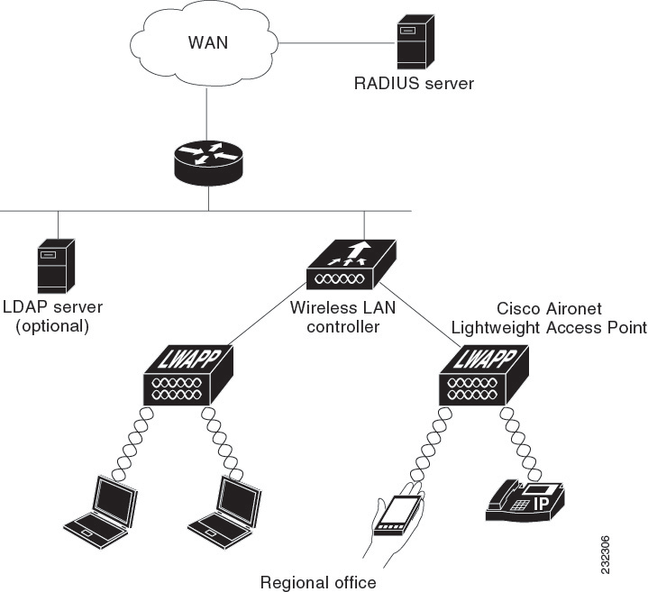
Local EAP is an authentication method that allows users and wireless clients to be authenticated locally. It is designed for use in remote offices that want to maintain connectivity to wireless clients when the backend system becomes disrupted or the external authentication server goes down. When you enable local EAP, the controller serves as the authentication server and the local user database, which removes dependence on an external authentication server. Local EAP retrieves user credentials from the local user database or the LDAP backend database to authenticate users. Local EAP supports LEAP, EAP-FAST, EAP-TLS, P EAPv0/MSCHAPv2, and PEAPv1/GTC authentication between the controller and wireless clients.
Note | The LDAP backend database supports these local EAP methods: EAP-TLS, EAP-FAST/GTC, and PEAPv1/GTC. LEAP, EAP-FAST/MSCHAPv2, and PEAPv0/MSCHAPv2 are also supported but only if the LDAP server is set up to return a clear-text password. |
Note | Cisco wireless LAN controllers support Local EAP authentication against external LDAP databases such as Microsoft Active Directory and Novell’s eDirectory. For more information about configuring the controller for Local EAP authentication against Novell’s eDirectory, see the Configure Unified Wireless Network for Authentication Against Novell's eDirectory Database whitepaper at http://www.cisco.com/c/en/us/support/docs/wireless/4400-series-wireless-lan-controllers/112137-novell-edirectory-00.html |
Note | Local authentication with certificates of second level hierarchy (CA + intermediate CA + device) is not supported. |
If any RADIUS servers are configured on the controller, the controller tries to authenticate the wireless clients using the RADIUS servers first. Local EAP is attempted only if no RADIUS servers are found, either because the RADIUS servers timed out or no RADIUS servers were configured. If four RADIUS servers are configured, the controller attempts to authenticate the client with the first RADIUS server, then the second RADIUS server, and then local EAP. If the client attempts to then reauthenticate manually, the controller tries the third RADIUS server, then the fourth RADIUS server, and then local EAP. If you never want the controller to try to authenticate clients using an external RADIUS server, enter these CLI commands in this order:
Restrictions on Local EAP
Configuring Local EAP (GUI)
Note | EAP-TLS, P EAPv0/MSCHAPv2, and PEAPv1/GTC use certificates for authentication, and EAP-FAST uses either certificates or PACs. The controller is shipped with Cisco-installed device and Certificate Authority (CA) certificates. However, if you want to use your own vendor-specific certificates, they must be imported on the controller. |
| Step 1 | If you are configuring local EAP to use one of the EAP types listed in the note above, make sure that the appropriate certificates and PACs (if you will use manual PAC provisioning) have been imported on the controller. |
| Step 2 | If you want the controller to retrieve user credentials from the local user database, make sure that you have properly configured the local network users on the controller. |
| Step 3 | If you want the controller to retrieve user credentials from an LDAP backend database, make sure that you have properly configured an LDAP server on the controller. |
| Step 4 | Specify the order in which
user credentials are retrieved from the backend database servers as follows:
|
| Step 5 | Specify values
for the local EAP timers as follows:
|
| Step 6 | Specify values for the
Advanced EAP parameters as follows:
|
| Step 7 | Create a local EAP profile,
which specifies the EAP authentication types that are supported on the wireless
clients as follows:
|
| Step 8 | If you created an EAP-FAST
profile, follow these steps to configure the EAP-FAST parameters:
|
| Step 9 | Enable local EAP on a WLAN
as follows:
|
| Step 10 | Enable EAP
parameters on a WLAN as follows:
|
| Step 11 | Click Save Configuration to save your changes. |
Configuring Local EAP (CLI)
Note | EAP-TLS, P EAPv0/MSCHAPv2, and PEAPv1/GTC use certificates for authentication, and EAP-FAST uses either certificates or PACbs. The controller is shipped with Cisco-installed device and Certificate Authority (CA) certificates. However, if you want to use your own vendor-specific certificates, they must be imported on the controller. |
| Step 1 | If you are configuring local EAP to use one of the EAP types listed in the note above, make sure that the appropriate certificates and PACs (if you will use manual PAC provisioning) have been imported on the controller. | ||||||
| Step 2 | If you want the controller to retrieve user credentials from the local user database, make sure that you have properly configured the local network users on the controller. | ||||||
| Step 3 | If you want the controller to retrieve user credentials from an LDAP backend database, make sure that you have properly configured an LDAP server on the controller. | ||||||
| Step 4 | Specify the order in which
user credentials are retrieved from the local and/or LDAP databases by entering
this command:
config local-auth user-credentials {local | ldap}
| ||||||
| Step 5 | Specify values for
the local EAP timers by entering these commands:
| ||||||
| Step 6 | Specify
values for the local EAP timers on a WLAN by entering these commands:
| ||||||
| Step 7 | Create a local
EAP profile by entering this command:
config local-auth eap-profile add profile_name
| ||||||
| Step 8 | Add an EAP
method to a local EAP profile by entering this command:
config local-auth
eap-profile method add
method
profile_name
The supported methods are leap, fast, tls, and peap.
| ||||||
| Step 9 | Configure
EAP-FAST parameters if you created an EAP-FAST profile by entering this
command:
config local-auth method fast ? where ? is one of the following:
| ||||||
| Step 10 | Configure
certificate parameters per profile by entering these commands:
| ||||||
| Step 11 | Enable local
EAP and attach an EAP profile to a WLAN by entering this command:
config wlan local-auth enable profile_name wlan_id
| ||||||
| Step 12 | Save your changes by entering this command: | ||||||
| Step 13 | View
information pertaining to local EAP by entering these commands:
| ||||||
| Step 14 | (Optional) Troubleshoot local
EAP sessions by entering these commands:
|
MAC Filtering
MAC Filtering of WLANs
Information About MAC Filtering of WLANs
When you use MAC filtering for client or administrator authorization, you need to enable it at the WLAN level first. If you plan to use local MAC address filtering for any WLAN, use the commands in this section to configure MAC filtering for a WLAN.
Restrictions for MAC Filtering
-
MAC filtering cannot be configured for Guest LANs.
-
Central Authentication and Switching—MAC authentication takes priority over MAC filtering if an external RADIUS is configured for the WLAN.
-
Local Authentication and Switching—MAC authentication does not work if MAC filtering is not supported on local authentication.
-
Interface mapping and profile precedence—MAC filtering for the WLAN set to any WLAN/Interface requires a mandatory profile name, followed by the interface name for the traffic to work properly.
Enabling MAC Filtering
Use these commands to enable MAC filtering on a WLAN:
-
Enable MAC filtering by entering the config wlan mac-filtering enable wlan_id command.
-
Verify that you have MAC filtering enabled for the WLAN by entering the show wlan command.
When you enable MAC filtering, only the MAC addresses that you add to the WLAN are allowed to join the WLAN. MAC addresses that have not been added are not allowed to join the WLAN.
When a client tries to associate to a WLAN for the first time, the client gets authenticated with its MAC address from AAA server. If the authentication is successful, the client gets an IP address from DHCP server, and then the client is connected to the WLAN.
When the client roams or sends association request to the same AP or different AP and is still connected to WLAN, the client is not authenticated again to AAA server.
If the client is not connected to WLAN, then the client has to get authenticated from the AAA server.
Local MAC Filters
Information About Local MAC Filters
Controllers have built-in MAC filtering capability, similar to that provided by a RADIUS authorization server.
Prerequisites for Configuring Local MAC Filters
You must have AAA enabled on the WLAN to override the interface name.
Configuring Local MAC Filters (CLI)
Create a MAC filter entry on the controller by entering the config macfilter add mac_addr wlan_id [interface_name] [description] [IP_addr] command.
The following parameters are optional:
interface_name—The name of the interface. This interface name is used to override the interface configured to the WLAN.
description—A brief description of the interface in double quotes (for example, “Interface1”).
IP_addr—The IP address which is used for a passive client with the MAC address specified by the mac addr value above.
Assign an IP address to an existing MAC filter entry, if one was not assigned in the config macfilter add command by entering the config macfilter ip-address mac_addr IP_addr command.
Verify that MAC addresses are assigned to the WLAN by entering the show macfilter command.
Note | If MAC filtering is configured, the controller tries to authenticate the wireless clients using the RADIUS servers first. Local MAC filtering is attempted only if no RADIUS servers are found, either because the RADIUS servers timed out or no RADIUS servers were configured. |
MAC Authentication Failover to 802.1X
Configuring MAC Authentication Failover to 802.1X Authentication
You can configure the controller to start 802.1X authentication when MAC authentication with static WEP for the client fails. If the RADIUS server rejects an access request from a client instead of deauthenticating the client, the controller can force the client to undergo an 802.1X authentication. If the client fails the 802.1X authentication too, then the client is deauthenticated.
If MAC authentication is successful and the client requests for an 802.1X authentication, the client has to pass the 802.1X authentication to be allowed to send data traffic. If the client does not choose an 802.1X authentication, the client is declared to be authenticated if the client passes the MAC authentication.
Note | WLAN with WPA2 + 802.1X + WebAuth with WebAuth on MAC failure is not supported. |
Configuring MAC Authentication Failover to 802.1x Authentication (GUI)
Configuring MAC Authentication Failover to 802.1X Authentication (CLI)
config wlan security 802.1X on-macfilter-failure {enable | disable} wlan-id |
Configuring 802.11w
Restrictions for 802.11w
Cisco's legacy Management Frame Protection is not related to the 802.11w standard that is implemented in the 7.4 release.
The 802.11w standard is supported on all 802.11n capable APs from Cisco WLC release 7.5.
The 802.11w standard is supported on Cisco 2504, 5508, 8510, and WiSM2 WLCs.
The 802.11w standard is not supported on Cisco Flex 7510 WLC and vWLC.
802.11w cannot be applied on an open WLAN, WEP-encrypted WLAN, or a TKIP-encrypted WLAN.
The WLAN on which 802.11w is configured must have either WPA2-PSK or WPA2-802.1x security configured.
Information About 802.11w
Wi-Fi is a broadcast medium that enables any device to eavesdrop and participate either as a legitimate or rogue device. Control and management frames such as authentication/deauthentication, association/disassociation, beacons, and probes are used by wireless clients to select an AP and to initiate a session for network services.
Unlike data traffic which can be encrypted to provide a level of confidentiality, these frames must be heard and understood by all clients and therefore must be transmitted as open or unencrypted. While these frames cannot be encrypted, they must be protected from forgery to protect the wireless medium from attacks. For example, an attacker could spoof management frames from an AP to tear down a session between a client and AP.
The 802.11w standard for Management Frame Protection is implemented in the 7.4 release.
The 802.11w protocol applies only to a set of robust management frames that are protected by the Management Frame Protection (PMF) service. These include Disassociation, Deauthentication, and Robust Action frames.
Management frames that are considered as robust action and therefore protected are the following:
-
Spectrum Management
-
QoS
-
DLS
-
Block Ack
-
Radio Measurement
-
Fast BSS Transition
-
SA Query
-
Protected Dual of Public Action
-
Vendor-specific Protected
When 802.11w is implemented in the wireless medium, the following occur:
-
Client protection is added by the AP adding cryptographic protection (by including the MIC information element) to deauthentication and disassociation frames preventing them from being spoofed in a DOS attack.
-
Infrastructure protection is added by adding a Security Association (SA) teardown protection mechanism consisting of an Association Comeback Time and an SA-Query procedure preventing spoofed association request from disconnecting an already connected client.
Configuring 802.11w (GUI)
| Step 1 | Choose WLANs > WLAN ID to open the WLANs > Edit page. | ||
| Step 2 | In the Security tab, choose the Layer 2 security tab. | ||
| Step 3 | From the Layer 2 Security drop-down list, choose WPA+WPA2. The 802.11w IGTK Key is derived using the 4-way handshake, which means that it can only be used on WLANs that are configured for WPA2 security at Layer 2.
| ||
| Step 4 | Choose the PMF state from the drop-down list | ||
| Step 5 | If you choose the PMF state as either Optional or Required, do the following: | ||
| Step 6 | In the Authentication Key Management section, follow these steps: | ||
| Step 7 | Click Apply. | ||
| Step 8 | Click Save Configuration. |
Configuring 802.11w (CLI)
Configure the 802.1X authentication for PMF by entering this command:
config wlan security wpa akm pmf 802.1x {enable | disable} wlan-id
Configure the preshared key support for PMF by entering this command:
config wlan security wpa akm pmf psk {enable | disable} wlan-id
If not done, configure a preshared key for a WLAN by entering this command:
config wlan security wpa akm psk set-key {ascii | hex} psk wlan-id
Configure protected management frames by entering this command:
config wlan security pmf {disable | optional | required} wlan-id
Configure the association comeback time settings by entering this command:
config wlan security pmf association-comeback timeout-in-seconds wlan-id
Configure the SA query retry timeout settings by entering this command:
config wlan security pmf saquery-retrytimeout timeout-in-milliseconds wlan-id
See the 802.11w configuration status for a WLAN by entering this command:
show wlan wlan-id
Configure the debugging of PMF by entering this command:
debug pmf events {enable | disable}
Fast Secure Roaming
802.11r Fast Transition
Information About 802.11r Fast Transition
802.11r, which is the IEEE standard for fast roaming, introduces a new concept of roaming where the initial handshake with the new AP is done even before the client roams to the target AP, which is called Fast Transition (FT). The initial handshake allows the client and APs to do the Pairwise Transient Key (PTK) calculation in advance. These PTK keys are applied to the client and AP after the client does the reassociation request or response exchange with new target AP.
The FT key hierarchy is designed to allow clients to make fast BSS transitions between APs without requiring reauthentication at every AP. WLAN configuration contains a new Authenticated Key Management (AKM) type called FT (Fast Transition).
From Release 8.0, you can create an 802.11r WLAN that is also an WPAv2 WLAN. In earlier releases, you had to create separate WLANs for 802.11r and for normal security. Non-802.11r clients can now join 802.11r-enabled WLANs as the 802.11r WLANs can accept non-802.11r associations. If clients do not support mixed mode or 802.11r join, they can join non-802.11r WLANS. When you configure FT PSK and later define PSK, clients that can join only PSK can now join the WLAN in mixed mode.
How a Client Roams
-
Over-the-Air—The client communicates directly with the target AP using IEEE 802.11 authentication with the FT authentication algorithm.
-
Over-the-DS—The client communicates with the target AP through the current AP. The communication between the client and the target AP is carried in FT action frames between the client and the current AP and is then sent through the controller.

Restrictions for 802.11r Fast Transition
-
This feature is not supported on mesh access points.
-
In 8.1 and earlier releases, this feature is not supported on access points in FlexConnect mode. In Release 8.2, this restriction is removed.
-
For access points in FlexConnect mode:
-
802.11r Fast Transition is supported in central and locally switched WLANs.
-
This feature is not supported for the WLANs enabled for local authentication.
-
802.11r client association is not supported on access points in standalone mode.
-
802.11r fast roaming is not supported on access points in standalone mode.
-
802.11r fast roaming between local authentication and central authentication WLAN is not supported.
-
802.11r fast roaming works only if the APs are in the same FlexConnect group.
-
-
This feature is not supported on Linux-based APs such as Cisco 600 Series OfficeExtend Access Points.
-
802.11r fast roaming is not supported if the client uses Over-the-DS preauthentication in standalone mode.
-
EAP LEAP method is not supported. WAN link latency prevents association time to a maximum of 2 seconds.
-
The service from standalone AP to client is only supported until the session timer expires.
-
TSpec is not supported for 802.11r fast roaming. Therefore, RIC IE handling is not supported.
-
If WAN link latency exists, fast roaming is also delayed. Voice or data maximum latency should be verified. The Cisco WLC handles 802.11r Fast Transition authentication request during roaming for both Over-the-Air and Over-the-DS methods.
-
This feature is supported on open and WPA2 configured WLANs.
-
Legacy clients cannot associate with a WLAN that has 802.11r enabled if the driver of the supplicant that is responsible for parsing the Robust Security Network Information Exchange (RSN IE) is old and not aware of the additional AKM suites in the IE. Due to this limitation, clients cannot send association requests to WLANs. These clients, however, can still associate with non-802.11r WLANs. Clients that are 802.11r capable can associate as 802.11i clients on WLANs that have both 802.11i and 802.11r Authentication Key Management Suites enabled.
The workaround is to enable or upgrade the driver of the legacy clients to work with the new 802.11r AKMs, after which the legacy clients can successfully associate with 802.11r enabled WLANs.
Another workaround is to have two SSIDs with the same name but with different security settings (FT and non-FT).
-
Fast Transition resource request protocol is not supported because clients do not support this protocol. Also, the resource request protocol is an optional protocol.
-
To avoid any Denial of Service (DoS) attack, each Cisco WLC allows a maximum of three Fast Transition handshakes with different APs.
-
Non-802.11r capable devices will not be able to associate with FT-enabled WLAN.
-
802.11r FT + PMF is not recommended.
-
802.11r FT Over-the-Air roaming is recommended for FlexConnect deployments.
-
In a default FlexGroup scenario, fast roaming is not supported.
Configuring 802.11r Fast Transition (GUI)
| Step 1 | Choose WLANs to open the WLANs window. | ||
| Step 2 | Click a WLAN ID to open the WLANs > Edit window. | ||
| Step 3 | Choose Security > Layer 2 tab. | ||
| Step 4 | From the
Layer 2 Security drop-down list, choose
WPA+WPA2.
The Authentication Key Management parameters for Fast Transition are displayed. | ||
| Step 5 | From the Fast Transition drop-down list, choose Fast Transition on the WLAN. | ||
| Step 6 | Check or uncheck
the
Over the
DS check box to enable or disable Fast Transition over a
distributed system.
This option is available only if you enable Fast Transition or if Fast Transition is adaptive. To use 802.11r Fast Transition over-the-air and over-the-ds must be disabled. | ||
| Step 7 | In the
Reassociation Timeout field, enter the number
of seconds after which the reassociation attempt of a client to an AP should
time out. The valid range is 1 to 100 seconds.
| ||
| Step 8 | Under
Authentication Key Management, choose
FT
802.1X or
FT
PSK. Check or uncheck the corresponding check boxes to enable or
disable the keys. If you check the
FT
PSK check box, from the PSK Format drop-down list, choose
ASCII or
Hex and enter the key value.
| ||
| Step 9 | From the WPA gtk-randomize State drop-down list, choose Enable or Disable to configure the Wi-Fi Protected Access (WPA) group temporal key (GTK) randomize state. | ||
| Step 10 | Click Apply to save your settings. |
Configuring 802.11r Fast Transition (CLI)
802.11r-enabled WLAN provides faster roaming for wireless client devices. However, if 802.11r is enabled on a WLAN and advertises fast transition (FT) and non-FT AKMs in Beacon and Probe RSN IE, some of the devices with bad implementation may not recognise FT/WPA2 authentication key-management (AKM) in RSN IE and fails to join. As a result, customers cannot enable 802.11r on the SSID.
To overcome this, Cisco Wireless infrastructure introduces adaptive 802.11r Feature. When FT mode is set to adaptive, WLAN advertises 802.11r Mobility Domain ID on an 802.11i-enabled WLAN. Apple iOS10 client devices identifies the presence of MDIE on a 80211i/WPA2 WLAN and does a proprietary handshake to establish 802.11r association. Once the client completes successful 802.11r association, it will be able to do FT roaming as in a normal 802.11r enabled WLAN.
The FT adaptive is applicable only to selected Apple iOS10 devices. All other clients will continue to have 802.11i association on the WLAN.
| Step 1 | To enable or
disable 802.11r fast transition parameters, use the
config wlan security
ft {adaptive
|
enable |
disable}
wlan-id command.
Fast Transition adaptive option is enabled by default when you create a new WLAN, from Cisco Wireless Controller (WLC), Release 8.3, onwards. However, the existing WLANs will retain its current configuration when Cisco WLC upgrades to Release 8.3 from an earlier release. Enable Fast SSID feature for allowing client devices a smother switching smoother switching from one WLAN to another. For more information on Fast SSID Change, see Configuring Fast SSID Changing. | ||
| Step 2 | To enable or disable 802.11r fast transition parameters over a distributed system, use the config wlan security ft over-the-ds {enable | disable} wlan-id command. The Client devices normally prefer fast transition over-the-ds if the capability is advertised in the WLAN. To force a client to perform fast transition over-the-air, disable fast transition over-the-ds. | ||
| Step 3 | To enable or
disable the authentication key management for fast transition using preshared
keys (PSK), use the
config wlan security wpa akm
ft psk {enable |
disable}
wlan-id command.
By default, the authentication key management using PSK is disabled. | ||
| Step 4 | To enable or disable authentication key management for adaptive using PSK, use the config wlan security wpa akm psk {enable | disable} wlan-id command. | ||
| Step 5 | To enable or
disable authentication key management for fast transition using 802.1X, use the
config wlan security wpa akm
ft-802.1X
{enable |
disable}
wlan-id command.
By default, authentication key management using 802.1X is enabled. | ||
| Step 6 | To enable or
disable authentication key management for adaptive using 802.1x, use the
config wlan security wpa
akm 802.1x
{enable |
disable}
wlan-id command.
| ||
| Step 7 | To enable or
disable 802.11r fast transition reassociation timeout, use the
config wlan security ft
reassociation-timeout
timeout-in-seconds wlan-id command.
The valid range is 1 to 100 seconds. The default value of reassociation timeout is 20 seconds. | ||
| Step 8 | To view the fast transition configuration on a WLAN, use the show wlan wlan-id command. | ||
| Step 9 | To view the
fast transition configuration on a client, use the
show client detail
client-mac command.
| ||
| Step 10 | To enable or disable debugging of fast transition events, use the debug ft events {enable | disable} command. |
What to Do Next
-
The tech support command output and xml config will not display fast transition information, when it is disabled.
-
The tech support command output and xml config will display Adaptive 802.11r information, when it is enabled.
-
To display a comprehensive view of the current Cisco WLC configuration, use the show run-config all command.
-
The fast transition adaptive mode is not supported on Releases prior to Release 8.3, the fast transition adaptive WLANs default to fast transition disable when Cisco WLC is downgraded from Release 8.3 to a previous release, and the fast transition adaptive configuration is invalidated.
Troubleshooting 802.11r BSS Fast Transition
| Symptom | Resolution |
|---|---|
| Non-802.11r legacy clients are no longer connecting. | Check if the WLAN has FT enabled. If so, non-FT WLAN will need to be created. |
| When configuring WLAN, the FT setup options are not shown. | Check if WPA2 is being used (802.1x / PSK). FT is supported only on WPA2 and OPEN SSIDs. |
| 802.11r clients appear to reauthenticate when they do a Layer 2 roam to a new controller. | Check if the reassociation timeout has been lowered from the default of 20 by navigating to WLANs > WLAN Name > Security > Layer 2 on the controller GUI. |
Sticky Key Caching
Information About Sticky Key Caching
The controller supports sticky key caching (SKC). With sticky key caching, the client receives and stores a different PMKID for every AP it associates with. The APs also maintain a database of the PMKID issued to the client.
In SKC, the client stores each Pairwise Master Key ID (PMKID) against a Pairwise Master Key Security Association (PMKSA). When a client finds an AP for which it has the PMKSA, it sends the PMKID in the association request to the AP. If the PMKSA is alive in the AP, the AP provides support for fast roaming. In SKC, full authentication is done on each new AP to which the client associates and the client must keep the PMKSA associated with all APs. For SKC, PMKSA is a per AP cache that the client stores and PMKSA is precalculated based on the BSSID of the new AP.
Restrictions for Sticky Key Caching
The controller supports SKC for up to eight APs per client. If a client roams to more than 8 APs per session, the old APs are removed to store the newly cached entries when the client roams. We recommend that you do not use SKC for large scale deployments.
SKC works only on WPA2-enabled WLANs.
SKC does not work across controllers in a mobility group.
SKC works only on local mode APs.
Configuring Sticky Key Caching (CLI)
| Step 1 | Disable the WLAN by entering this command: | ||
| Step 2 | Enable sticky key caching by entering this command: config wlan security wpa wpa2 cache sticky enable wlan_id By default, SKC is disabled and opportunistic key caching (OKC) is enabled.
You can check if SKC is enabled by entering this command: show wlan wlan_id Information similar to the following appears: WLAN Identifier.................................. 2 Profile Name..................................... new Network Name (SSID).............................. new Status........................................... Disabled MAC Filtering.................................... Disabled Security 802.11 Authentication:........................ Open System Static WEP Keys............................... Disabled 802.1X........................................ Disabled Wi-Fi Protected Access (WPA/WPA2)............. Enabled WPA (SSN IE)............................... Disabled WPA2 (RSN IE).............................. Enabled TKIP Cipher............................. Disabled AES Cipher.............................. Enabled Auth Key Management 802.1x.................................. Disabled PSK..................................... Enabled CCKM.................................... Disabled FT(802.11r)............................. Disabled FT-PSK(802.11r)......................... Disabled SKC Cache Support......................... Enabled FT Reassociation Timeout................... 20 FT Over-The-Air mode....................... Enabled FT Over-The-Ds mode........................ Enabled CCKM tsf Tolerance............................... 1000 Wi-Fi Direct policy configured................ Disabled EAP-Passthrough............................... Disabled | ||
| Step 3 | Enable the WLAN by entering this command: config wlan enable wlan_id | ||
| Step 4 | Save your settings by entering this command: save config |
Encryption
WLAN for Static WEP
Information About WLAN for Static WEP
You can configure up to four WLANs to support static WEP keys. Follow these guidelines when configuring a WLAN for static WEP:
-
When you configure static WEP as the Layer 2 security policy, no other security policies can be specified. That is, you cannot configure web authentication. However, when you configure static WEP as the Layer 2 security policy, you can configure web authentication.
Note | Dynamic WEP encryption method is not supported. The last release to support this method was Release 7.0 (7.0.240.0 and later 7.0 releases). |
WPA1 and WPA2
Wi-Fi Protected Access (WPA or WPA1) and WPA2 are standards-based security solutions from the Wi-Fi Alliance that provide data protection and access control for wireless LAN systems. WPA1 is compatible with the IEEE 802.11i standard but was implemented prior to the standard’s ratification; WPA2 is the Wi-Fi Alliance's implementation of the ratified IEEE 802.11i standard.
By default, WPA1 uses Temporal Key Integrity Protocol (TKIP) and message integrity check (MIC) for data protection while WPA2 uses the stronger Advanced Encryption Standard encryption algorithm using Counter Mode with Cipher Block Chaining Message Authentication Code Protocol (AES-CCMP). Both WPA1 and WPA2 use 802.1X for authenticated key management by default. However, these options are also available:
802.1X—The standard for wireless LAN security, as defined by IEEE, is called 802.1X for 802.11, or simply 802.1X. An access point that supports 802.1X acts as the interface between a wireless client and an authentication server, such as a RADIUS server, to which the access point communicates over the wired network. If 802.1X is selected, only 802.1X clients are supported.
PSK—When you choose PSK (also known as WPA preshared key or WPA passphrase), you need to configure a preshared key (or a passphrase). This key is used as the pairwise master key (PMK) between the clients and the authentication server.
CCKM—Cisco Centralized Key Management (CCKM) uses a fast rekeying technique that enables clients to roam from one access point to another without going through the controller, typically in under 150 milliseconds (ms). CCKM reduces the time required by the client to mutually authenticate with the new access point and derive a new session key during reassociation. CCKM fast secure roaming ensures that there is no perceptible delay in time-sensitive applications such as wireless Voice over IP (VoIP), enterprise resource planning (ERP), or Citrix-based solutions. CCKM is a CCXv4-compliant feature. If CCKM is selected, only CCKM clients are supported.
When CCKM is enabled, the behavior of access points differs from the controller's for fast roaming in the following ways:
If an association request sent by a client has CCKM enabled in a Robust Secure Network Information Element (RSN IE) but CCKM IE is not encoded and only PMKID is encoded in RSN IE, then the controller does not do a full authentication. Instead, the controller validates the PMKID and does a four-way handshake.
If an association request sent by a client has CCKM enabled in RSN IE but CCKM IE is not encoded and only PMKID is encoded in RSN IE, then AP does a full authentication. The access point does not use PMKID sent with the association request when CCKM is enabled in RSN IE.
802.1X+CCKM—During normal operation, 802.1X-enabled clients mutually authenticate with a new access point by performing a complete 802.1X authentication, including communication with the main RADIUS server. However, when you configure your WLAN for 802.1X and CCKM fast secure roaming, CCKM-enabled clients securely roam from one access point to another without the need to reauthenticate to the RADIUS server. 802.1X+CCKM is considered optional CCKM because both CCKM and non-CCKM clients are supported when this option is selected.
On a single WLAN, you can allow WPA1, WPA2, and 802.1X/PSK/CCKM/802.1X+CCKM clients to join. All of the access points on such a WLAN advertise WPA1, WPA2, and 802.1X/PSK/CCKM/ 802.1X+CCKM information elements in their beacons and probe responses. When you enable WPA1 and/or WPA2, you can also enable one or two ciphers, or cryptographic algorithms, designed to protect data traffic. Specifically, you can enable AES and/or TKIP data encryption for WPA1 and/or WPA2. TKIP is the default value for WPA1, and AES is the default value for WPA2.
Restrictions for Configuring Static WEP
-
The OEAP 600 series does not support fast roaming for clients. Dual mode voice clients will experience reduced call quality when they roam between the two spectrums on OEAP602 access point. We recommend that you configure voice devices to only connect on one band, either 2.4 GHz or 5 GHz.
-
The Cisco WLC software supports CCX versions 1 through 5. CCX support is enabled automatically for every WLAN on the controller and cannot be disabled. The controller stores the CCX version of the client in its client database and uses it to limit client functionality. Clients must support CCXv4 or v5 in order to use CCKM. For more information about CCX, see the Configuring Cisco Client Extensions section.
-
In a unified architecture where multiple VLAN clients are supported for a WGB, you also need to configure encryption cipher suite and WEP keys globally, when the WEP encryption is enabled on the WGB. Otherwise, multicast traffic for wired VLAN clients fail.
Configuring WPA1+WPA2 (GUI)
| Step 1 | Choose WLANs to open the WLANs page. | ||||
| Step 2 | Click the ID number of the desired WLAN to open the WLANs > Edit page. | ||||
| Step 3 | Choose the Security and Layer 2 tabs to open the WLANs > Edit (Security > Layer 2) page. | ||||
| Step 4 | Choose WPA+WPA2 from the Layer 2 Security drop-down list. | ||||
| Step 5 | Under WPA+WPA2 Parameters, select the
WPA Policy check
box to enable WPA1, select the
WPA2 Policy check
box to enable WPA2, or select both check boxes to enable both WPA1 and WPA2.
| ||||
| Step 6 | Select the
WPA2 Policy-AES check box to
enable AES data encryption
.
| ||||
| Step 7 | Choose one of the following
key management methods from the Auth Key Mgmt drop-down list:
802.1X,
CCKM,
PSK, or
802.1X+CCKM.
| ||||
| Step 8 | If you chose PSK in
Step 7, choose
ASCII or
HEX from the PSK
Format drop-down list and then enter a preshared key in the blank text box. WPA
preshared keys must contain 8 to 63 ASCII text characters or 64 hexadecimal
characters.
| ||||
| Step 9 | Click Apply to commit your changes. | ||||
| Step 10 | Click Save Configuration to save your changes. |
Configuring WPA1+WPA2 (CLI)
| Step 1 | Disable the WLAN by entering this command: | ||||
| Step 2 | Enable or disable WPA for the WLAN by entering this command: | ||||
| Step 3 | Enable or disable WPA1 for the WLAN by entering this command: | ||||
| Step 4 | Enable or disable WPA2 for the WLAN by entering this command: | ||||
| Step 5 | Enable or disable AES or TKIP
data encryption for WPA1 or WPA2 by entering one of these commands:
The default values are TKIP for WPA1 and AES for WPA2.
When you have VLAN configuration on WGB, you need to configure the encryption cipher mode and keys for a particular VLAN, for example, encryption vlan 80 mode ciphers tkip. Then, you need configure the encryption cipher mode globally on the multicast interface by entering the following command: encryption mode ciphers tkip. | ||||
| Step 6 | Enable or disable 802.1X, PSK, or CCKM authenticated key management by entering this command:
config wlan security wpa akm {802.1X | psk | cckm} {enable | disable} wlan_id | ||||
| Step 7 | If you enabled PSK in
Step 6, enter this command to specify a preshared key:
config wlan security wpa akm psk set-key {ascii | hex} psk-key wlan_id WPA preshared keys must contain 8 to 63 ASCII text characters or 64 hexadecimal characters. | ||||
| Step 8 | Enable or disable authentication key management suite for fast transition by entering this command:
config wlan security wpa akm ft {802.1X | psk} {enable | disable} wlan_id
| ||||
| Step 9 | Enable or disable randomization of group temporal keys (GTK) between AP and clients by entering this command:
config wlan security wpa gtk-random {enable | disable} wlan_id | ||||
| Step 10 | If you enabled WPA2 with 802.1X authenticated key management or WPA1 or WPA2 with CCKM authenticated key management, the PMK cache lifetime timer is used to trigger reauthentication with the client when necessary. The timer is based on the timeout value received from the AAA server or the WLAN session timeout setting. To see the amount of time remaining before the timer expires, enter this command:
If you enabled WPA2 with 802.1X authenticated key management, the controller supports both opportunistic PMKID caching and sticky (or non-opportunistic) PMKID caching. In sticky PMKID caching (SKC), the client stores multiple PMKIDs, a different PMKID for every AP it associates with. Opportunistic PMKID caching (OKC) stores only one PMKID per client. By default, the controller supports OKC. | ||||
| Step 11 | Enable the WLAN by entering this command: | ||||
| Step 12 | Save your settings by entering this command: |
CKIP
Information About CKIP
Cisco Key Integrity Protocol (CKIP) is a Cisco-proprietary security protocol for encrypting 802.11 media. CKIP improves 802.11 security in infrastructure mode using key permutation, a message integrity check (MIC), and a message sequence number. Software release 4.0 or later releases support CKIP with a static key. For this feature to operate correctly, you must enable Aironet information elements (IEs) for the WLAN.
A lightweight access point advertises support for CKIP in beacon and probe response packets by adding an Aironet IE and setting one or both of the CKIP negotiation bits (key permutation and multi-modular hash message integrity check [MMH MIC]). Key permutation is a data encryption technique that uses the basic encryption key and the current initialization vector (IV) to create a new key. MMH MIC prevents bit-flip attacks on encrypted packets by using a hash function to compute message integrity code.
The CKIP settings specified in a WLAN are mandatory for any client attempting to associate. If the WLAN is configured for both CKIP key permutation and MMH MIC, the client must support both. If the WLAN is configured for only one of these features, the client must support only the CKIP feature.
Note | CKIP is supported for use only with static WEP. It is not supported for use with dynamic WEP. Therefore, a wireless client that is configured to use CKIP with dynamic WEP is unable to associate to a WLAN that is configured for CKIP. We recommend that you use either dynamic WEP without CKIP (which is less secure) or WPA/WPA2 with TKIP or AES (which are more secure). |
Configuring CKIP (GUI)
| Step 1 | Choose WLANs to open the WLANs page. |
| Step 2 | Click the ID number of the desired WLAN to open the WLANs > Edit page. |
| Step 3 | Choose the Advanced tab. |
| Step 4 | Select the Aironet IE check box to enable Aironet IEs for this WLAN and click Apply. |
| Step 5 | Choose the General tab. |
| Step 6 | Unselect the Status check box, if selected, to disable this WLAN and click Apply. |
| Step 7 | Choose the Security and Layer 2 tabs to open the WLANs > Edit (Security > Layer 2) page. |
| Step 8 | Choose CKIP from the Layer 2 Security drop-down list. |
| Step 9 | Under CKIP Parameters, choose the length of the CKIP encryption key from the Key Size drop-down list.The range is Not Set, 40 bits, or 104 bits and the default is Not Set. |
| Step 10 | Choose the number to be assigned to this key from the Key Index drop-down list. You can configure up to four keys. |
| Step 11 | From the Key Format drop-down list, choose ASCII or HEX and then enter an encryption key in the Encryption Key text box. 40-bit keys must contain 5 ASCII text characters or 10 hexadecimal characters. 104-bit keys must contain 13 ASCII text characters or 26 hexadecimal characters. |
| Step 12 | Select the MMH Mode check box to enable MMH MIC data protection for this WLAN. The default value is disabled (or unselected). |
| Step 13 | Select the Key Permutation check box to enable this form of CKIP data protection. The default value is disabled (or unselected). |
| Step 14 | Click Apply to commit your changes. |
| Step 15 | Choose the General tab. |
| Step 16 | Select the Status check box to enable this WLAN. |
| Step 17 | Click Apply to commit your changes. |
| Step 18 | Click Save Configuration to save your changes. |
Configuring CKIP (CLI)
| Step 1 | Disable the WLAN by entering this command: |
| Step 2 | Enable Aironet IEs for this WLAN by entering this command: |
| Step 3 | Enable or disable CKIP for the WLAN by entering this command: |
| Step 4 | Specify a CKIP encryption key for the WLAN by entering this command: config wlan security ckip akm psk set-key wlan_id {40 | 104} {hex | ascii} key key_index |
| Step 5 | Enable or disable CKIP MMH MIC for the WLAN by entering this command: config wlan security ckip mmh-mic {enable | disable} wlan_id |
| Step 6 | Enable or disable CKIP key permutation for the WLAN by entering this command: |
| Step 7 | Enable the WLAN by entering this command: |
| Step 8 | Save your settings by entering this command: |
Layer 3 Security
Configuring Layer 3 Security Using Web Authentication
Prerequisites for Configuring Web Authentication on a WLAN
-
To initiate HTTP/HTTPS web authentication redirection, use HTTP URL or HTTPS URL.
-
If the CPU ACLs are configured to block HTTP / HTTPS traffic, after the successful web login authentication, there could be a failure in the redirection page.
-
Before enabling web authentication, make sure that all proxy servers are configured for ports other than port 53.
-
When you enable web authentication for a WLAN, a message appears indicating that the controller forwards DNS traffic to and from wireless clients prior to authentication. We recommend that you have a firewall or intrusion detection system (IDS) behind your guest VLAN to regulate DNS traffic and to prevent and detect any DNS tunneling attacks.
-
If the web authentication is enabled on the WLAN and you also have the CPU ACL rules, the client-based web authentication rules take higher precedence as long as the client is unauthenticated (in the webAuth_Reqd state). Once the client goes to the RUN state, the CPU ACL rules get applied. Therefore, if the CPU ACL rules are enabled in the controller, an allow rule for the virtual interface IP is required (in any direction) with the following conditions:
-
The allow rule for the virtual IP should be for TCP protocol and port 80 (if secureweb is disabled) or port 443 (if secureweb is enabled). This process is required to allow client’s access to the virtual interface IP address, post successful authentication when the CPU ACL rules are in place.
Restrictions for Configuring Web Authentication on a WLAN
- Web authentication is supported only with these Layer 2 security policies: open authentication, open authentication+WEP, and WPA-PSK. With the 7.4 release, web authentication is supported for use with 802.1X.
- Special charecters are not supported in the username field for web-authentication.
When clients connect to a WebAuth SSID and a preauthorization ACL configured to allow VPN users, the clients will get disconnected from the SSID every few minutes. Webauth SSIDs must not connect without authenticating on the web page.
You can select the following identity stores to authenticate web-auth user, under WLANs > Security > AAA servers > Authentication priority order for web-auth user section: If multiple identity stores are selected, then the controller checks each identity store in the list, in the order specified, from top to bottom, until authentication for the user succeeds. The authentication fails, if the controller reaches the end of the list and user remains un-authenticated in any of the identity stores.
Information About Web Authentication
WLANs can use web authentication only if VPN passthrough is not enabled on the controller. Web authentication is simple to set up and use and can be used with SSL to improve the overall security of the WLAN.
Using Web Authentication with 802.1x
- Session timer—Client session timeout configured for a WLAN that requires reauthentication. This timer starts after a successful web authentication.
- Reauthentication timer—Timer that is used to trigger client reauthentication for WPA1.
- PMK cache timer—Cache lifetime timer that is used to trigger client reauthentication for WPA2.
This section describes the two scenarios that clients can encounter when a WLAN is configured to use web authentication along with 802.1x.
Client associated to a single controller—In this scenario, when the reauthentication or PMK cache timer expires, the client reauthenticates, updates the reauthentication/PMK cache timer and remains in the run state. When the client session timer (ST) expires, the client is deauthenticated even if the reauthentication/PMK cache timer is still valid.
Client roams from one controller to another controller—In this scenario, after the client roams the foreign controller triggers an L2 authentication and the anchor controller triggers an L3 authentication. The 802.1x reauthentication/PMK timer runs on the foreign controller and the client session timer runs on the anchor controller. When the reauthentication/PMK timer expires, 802.1x client reauthentication happens and the client is in the run state. Client is deauthenticated only when the client session timer expires.
- If we have AAA user with AAA override enabled, the session timeout is received from the RADIUS server.
- If we have AAA user with AAA override disabled, the session timeout is taken from the corresponding WLAN.
- If we use local authentication, 802.1x reauthentication/PMK cache timer is the WLAN ST value and web authentication local user remaining lifetime is configured as ST.
Note | We can have same or different users for both 802.1x and web authentication. |
Configuring Web Authentication
Configuring Web Authentication (GUI)
| Step 1 | Choose WLANs to open the WLANs page. |
| Step 2 | Click the ID number of the WLAN for which you want to configure web authentication. The WLANs > Edit page appears. |
| Step 3 | Choose the Security and Layer 3 tabs to open the WLANs > Edit (Security > Layer 3) page. |
| Step 4 | Select the Web Policy check box. |
| Step 5 | Make sure that the Authentication option is selected. |
| Step 6 | Click Apply to commit your changes. |
| Step 7 | Click Save Configuration to save your settings. |
Configuring Web Authentication (CLI)
| Step 1 | Enable or disable web authentication on a particular WLAN by entering this command: |
| Step 2 | Release the guest user IP address when the web authentication policy timer expires and prevent the guest user from acquiring an IP address for 3 minutes by entering this command: config wlan webauth-exclude wlan_id {enable | disable} The default value is disabled. This command is applicable when you configure the internal DHCP scope on the controller. By default, when the web authentication timer expires for a guest user, the user can immediately reassociate to the same IP address before another guest user can acquire it. If there are many guest users or limited IP addresses in the DHCP pool, some guest users might not be able to acquire an IP address. When you enable this feature on the guest WLAN, the guest user’s IP address is released when the web authentication policy timer expires and the guest user is excluded from acquiring an IP address for 3 minutes. The IP address is available for another guest user to use. After 3 minutes, the excluded guest user can reassociate and acquire an IP address, if available. |
| Step 3 | See the status of web authentication by entering this command: |
Web Authentication Proxy
Information About the Web Authentication Proxy
This feature enables clients that have manual web proxy enabled in the browser to facilitate authentication with the controller. If the user's browser is configured with manual proxy settings with a configured port number as 8080 or 3128 and if the client requests any URL, the controller responds with a web page prompting the user to change the Internet proxy settings to automatically detect the proxy settings so that the browser’s manual proxy settings information does not get lost. After enabling this settings, the user can get access to the network through the web authentication policy. This functionality is given for port 8080 and 3128 because these are the most commonly used ports for the web proxy server.
Note | The web authentication proxy redirect ports are not blocked through CPU ACL. If a CPU ACL is configured to block the port 8080, 3128, and one random port as part of web authentication proxy configuration, those ports are not blocked because the webauth rules take higher precedence than the CPU ACL rules unless the client is in the webauth_req state. |
A web browser has the following three types of Internet settings that you can configure:
In a manual proxy server configuration, the browser uses the IP address of a proxy server and a port. If this configuration is enabled on the browser, the wireless client communicates with the IP address of the destination proxy server on the configured port. In a web authentication scenario, the controller does not listen to such proxy ports and the client is not able to establish a TCP connection with the controller. The user is unable to get any login page to authentication and get access to the network.
When a wireless client enters a web-authenticated WLAN, the client tries to access a URL. If a manual proxy configuration is configured on the client's browser, all the web traffic going out from the client will be destined to the proxy IP and port configured on the browser.
-
A TCP connection is established between the client and the proxy server IP address that the controller proxies for.
-
The client processes the DHCP response and obtains a JavaScript file from the controller. The script disables all proxy configurations on the client for that session.
Note
For external clients, the controller sends the login page as is (with or without JavaScipt).
-
Any requests that bypass the proxy configuration. The controller can then perform web-redirection, login, and authentication.
-
When the client goes out of the network, and then back into its own network, a DHCP refresh occurs and the client continues to use the old proxy configuration configured on the browser.
-
If the external DHCP server is used with webauth proxy, then DHCP option 252 must be configured on the DHCP server for that scope. The value of option 252 will have the format http://<virtual ip>/proxy.js. No extra configuration is needed for internal DHCP servers.
Note
When you configure FIPS mode with secure web authentication, we recommend that you use Mozilla Firefox as your browser.
-
If web authentication redirect to HTTPS is enabled, then both the client HTTPS and client HTTP requests are redirected to HTTPS web authentication.
Note
This enhancement was introduced in Release 8.0.
Configuring the Web Authentication Proxy (GUI)
| Step 1 | Choose Controller > General |
| Step 2 | From the WebAuth Proxy Redirection Mode drop-down list, choose Enabled or Disabled. |
| Step 3 | In the WebAuth Proxy Redirection Port text box, enter the port number of the web auth proxy. This text box consists of the port numbers on which the controller listens to for web authentication proxy redirection. By default, the three ports 80, 8080, and 3128 are assumed. If you configured the web authentication redirection port to any port other than these values, you must specify that value. |
| Step 4 | Click Apply. |
Configuring the Web Authentication Proxy (CLI)
Enable web authentication proxy redirection by entering this command: config network web-auth proxy-redirect {enable | disable}
Configure the secure web (HTTPS) authentication for clients by entering this command: config network web-auth secureweb {enable | disable}
The default secure web (HTTPS) authentication for clients is enabled.
Note
If you configure to disallow secure web (HTTPS) authentication for clients using the config network web-auth secureweb disable command, then you must reboot the Cisco WLC to implement the change.Set the web authentication port number by entering this command: config network web-auth port port-number
This parameter specifies the port numbers on which the controller listens to for web authentication proxy redirection. By default, the three ports 80, 8080, and 3128 are assumed. If you configured the web authentication redirection port to any port other than these values, you must specify that value.
Configure secure redirection (HTTPS) for web authentication clients by entering this command: config network web-auth https-redirect {enable | disable}
See the current status of the web authentication proxy configuration by entering one of the following commands:
Captive Portal Bypass
Information About Captive Bypassing
WISPr is a draft protocol that enables users to roam between different wireless service providers. Some devices (For example, Apple iOS devices) have a mechanism using which they can determine if the device is connected to Internet, based on an HTTP WISPr request made to a designated URL. This mechanism is used for the device to automatically open a web browser when a direct connection to the internet is not possible. This enables the user to provide his credentials to access the internet. The actual authentication is done in the background every time the device connects to a new SSID.
The client device (Apple IOS device) sends a WISPr request to the controller, which checks for the user agent details and then triggers an HTTP request with a web authentication interception in the controller. After verification of the IOS version and the browser details provided by the user agent, the controller allows the client to bypass the captive portal settings and provides access to the Internet.
Note | The captive portal bypass for IOS7 is supported only with Cisco Wireless LAN Controller, Release 7.6. |
This HTTP request triggers a web authentication interception in the controller as any other page requests are performed by a wireless client. This interception leads to a web authentication process, which will be completed normally. If the web authentication is being used with any of the controller splash page features (URL provided by a configured RADIUS server), the splash page may never be displayed because the WISPr requests are made at very short intervals, and as soon as one of the queries is able to reach the designated server, any web redirection or splash page display process that is performed in the background is aborted, and the device processes the page request, thus breaking the splash page functionality.
For example, Apple introduced an iOS feature to facilitate network access when captive portals are present. This feature detects the presence of a captive portal by sending a web request on connecting to a wireless network. This request is directed to http://www.apple.com/library/test/success.html for Apple IOS version 6 and older, and to several possible target URLs for Apple IOS version 7 and later. If a response is received, then the Internet access is assumed to be available and no further interaction is required. If no response is received, then the Internet access is assumed to be blocked by the captive portal and Apple’s Captive Network Assistant (CNA) auto-launches the pseudo-browser to request portal login in a controlled window. The CNA may break when redirecting to an ISE captive portal. The controller prevents this pseudo-browser from popping up.
You can now configure the controller to bypass WISPr detection process, so the web authentication interception is only done when a user requests a web page leading to splash page load in user context, without the WISPr detection being performed in the background.
Configuring Captive Bypassing (CLI)
Use these commands to configure captive bypassing:
MAC Authentication Fallback to Web Authentication
Information About Fallback Policy with MAC Filtering and Web Authentication
You can configure a fallback policy mechanism that combines Layer 2 and Layer 3 security. In a scenario where you have both MAC filtering and web authentication implemented, when a client tries to connect to a WLAN using the MAC filter (RADIUS server), if the client fails the authentication, you can configure the authentication to fall back to web authentication. When a client passes the MAC filter authentication, the web authentication is skipped and the client is connected to the WLAN. With this feature, you can avoid disassociations based on only a MAC filter authentication failure.
Restrictions
-
Mobility is not supported for SSIDs with security type configured for Webauth on MAC filter failure.
-
MAC filtering does not support passthrough web-authentication. It supports only username and password for web-authentication.
Mobility is not supported for SSIDs with security type configured for Webauth on MAC filter failure.
Configuring a Fallback Policy with MAC Filtering and Web Authentication (GUI)
Note | Before configuring a fallback policy, you must have MAC filtering enabled. |
| Step 1 | Choose WLANs to open the WLANs page. | ||
| Step 2 | Click the ID number of the WLAN for which you want to configure the fallback policy for web authentication. The WLANs > Edit page appears. | ||
| Step 3 | Choose the Security and Layer 3 tabs to open the WLANs > Edit (Security > Layer 3) page. | ||
| Step 4 | From the Layer 3 Security drop-down list, choose None. | ||
| Step 5 | Select the Web Policy check box.
| ||
| Step 6 | Click On MAC Filter Failure. | ||
| Step 7 | Click Apply to commit your changes. | ||
| Step 8 | Click Save Configuration to save your settings. |
Configuring a Fallback Policy with MAC Filtering and Web Authentication (CLI)
Note | Before configuring a fallback policy, you must have MAC filtering enabled. To know more about how to enable MAC filtering, see the Information About MAC Filtering of WLANs section. |
| Step 1 | Enable or disable web authentication on a particular WLAN by entering this command: |
| Step 2 | See the web authentication status by entering this command:
FT Over-The-Ds mode.............................. Enabled CKIP ......................................... Disabled IP Security................................... Disabled IP Security Passthru.......................... Disabled Web Based Authentication...................... Enabled-On-MACFilter-Failure ACL............................................. Unconfigured Web Authentication server precedence: 1............................................... local 2............................................... radius 3............................................... ldap |
Web Redirect with 8021.X Authentication
Information About Web Redirect with 802.1X Authentication
You can configure a WLAN to redirect a user to a particular web page after 802.1X authentication has completed successfully. You can configure the web redirect to give the user partial or full access to the network.
Conditional Web Redirect
If you enable conditional web redirect, the user can be conditionally redirected to a particular web page after 802.1X authentication has completed successfully. You can specify the redirect page and the conditions under which the redirect occurs on your RADIUS server. Conditions might include the user’s password reaching expiration or the user needing to pay his or her bill for continued usage.
If the RADIUS server returns the Cisco AV-pair “url-redirect,” then the user is redirected to the specified URL upon opening a browser. If the server also returns the Cisco AV-pair “url-redirect-acl,” the specified access control list (ACL) is installed as a preauthentication ACL for this client. The client is not considered fully authorized at this point and can only pass traffic allowed by the preauthentication ACL.
After the client completes a particular operation at the specified URL (for example, changing a password or paying a bill), the client must reauthenticate. When the RADIUS server does not return a “url-redirect,” the client is considered fully authorized and allowed to pass traffic.
Note | The conditional web redirect feature is available only for WLANs that are configured for 802.1X or WPA+WPA2 Layer 2 security. |
After you configure the RADIUS server, you can then configure the conditional web redirect on the controller using either the controller GUI or CLI.
Splash Page Web Redirect
If you enable splash page web redirect, the user is redirected to a particular web page after 802.1X authentication has completed successfully. After the redirect, the user has full access to the network. You can specify the redirect page on your RADIUS server and the corresponding ACL to allow access to this server in "url-redirect-acl". If the RADIUS server returns the Cisco AV-pair “url-redirect,” then the user is redirected to the specified URL upon opening a browser. The client is considered fully authorized at this point and is allowed to pass traffic, even if the RADIUS server does not return a “url-redirect.”
Note | The splash page web redirect feature is available only for WLANs that are configured for 802.1X or WPA+WPA2 Layer 2 security with 802.1x key management. Preshared key management is not supported with any Layer 2 security method. |
Suppose there are backend applications running on the wireless clients and they use HTTP or HTTPS port for their communication. If the applications start communicating before the actual web page is opened, the redirect functionality does not work with web passthrough.
After you configure the RADIUS server, you can then configure the splash page web redirect on the controller using either the controller GUI or CLI.
Configuring the RADIUS Server (GUI)
Note | These instructions are specific to the CiscoSecure ACS; however, they should be similar to those for other RADIUS servers. |
| Step 1 | From the CiscoSecure ACS main menu, choose Group Setup. |
| Step 2 | Click Edit Settings. |
| Step 3 | From the Jump To drop-down list, choose RADIUS (Cisco IOS/PIX 6.0). |
| Step 4 | Select the [009\001] cisco-av-pair check box. |
| Step 5 | Enter the following Cisco AV-pairs in the [009\001] cisco-av-pair edit box to specify the URL to which the user is redirected and, if configuring conditional web redirect, the conditions under which the redirect takes place, respectively: |
Configuring Web Redirect
Configuring Web Redirect (GUI)
| Step 1 | Choose WLANs to open the WLANs page. |
| Step 2 | Click the ID number of the desired WLAN. The WLANs > Edit page appears. |
| Step 3 | Choose the Security and Layer 2 tabs to open the WLANs > Edit (Security > Layer 2) page. |
| Step 4 | From the Layer 2 Security drop-down list, choose 802.1X or WPA+WPA2. |
| Step 5 | Set any additional parameters for 802.1X or WPA+WPA2. |
| Step 6 | Choose the Layer 3 tab to open the WLANs > Edit (Security > Layer 3) page. |
| Step 7 | From the Layer 3 Security drop-down list, choose None. |
| Step 8 | Check the Web Policy check box. |
| Step 9 | Choose one of the following options to enable conditional or splash page web redirect: Conditional Web Redirect or Splash Page Web Redirect. The default value is disabled for both parameters. |
| Step 10 | If the user is to be redirected to a site external to the controller, choose the ACL that was configured on your RADIUS server from the Preauthentication ACL drop-down list. |
| Step 11 | Click Apply to commit your changes. |
| Step 12 | Click Save Configuration to save your changes. |
Configuring Web Redirect (CLI)
| Step 1 | Enable or disable conditional web redirect by entering this command: config wlan security cond-web-redir {enable | disable} wlan_id |
| Step 2 | Enable or disable splash page web redirect by entering this command: config wlan security splash-page-web-redir {enable | disable} wlan_id |
| Step 3 | Save your settings by entering this command: |
| Step 4 | See the status of the web redirect features for a particular WLAN by entering this command:
Information similar to the following appears: WLAN Identifier.................................. 1 Profile Name..................................... test Network Name (SSID).............................. test ... Web Based Authentication......................... Disabled Web-Passthrough.................................. Disabled Conditional Web Redirect......................... Disabled Splash-Page Web Redirect......................... Enabled ... |
Disabling Accounting Servers per WLAN (GUI)
Note | Disabling accounting servers disables all accounting operations and prevents the controller from falling back to the default RADIUS server for the WLAN. |
| Step 1 | Choose WLANs to open the WLANs page. |
| Step 2 | Click the ID number of the WLAN to be modified. The WLANs > Edit page appears. |
| Step 3 | Choose the Security and AAA Servers tabs to open the WLANs > Edit (Security > AAA Servers) page. |
| Step 4 | Unselect the Enabled check box for the Accounting Servers. |
| Step 5 | Click Apply to commit your changes. |
| Step 6 | Click Save Configuration to save your changes. |
Disabling Coverage Hole Detection per WLAN
Note | Coverage hole detection is enabled globally on the controller. |
Note | You can disable coverage hole detection on a per-WLAN basis. When you disable coverage hole detection on a WLAN, a coverage hole alert is still sent to the controller, but no other processing is done to mitigate the coverage hole. This feature is useful for guest WLANs where guests are connected to your network for short periods of time and are likely to be highly mobile. |
Disabling Coverage Hole Detection on a WLAN (GUI)
| Step 1 | Choose WLANs to open the WLANs page. | ||
| Step 2 | Click the profile name of the WLAN to be modified. The WLANs > Edit page appears. | ||
| Step 3 | Choose the Advanced tab to display the WLANs > Edit (Advanced) page. | ||
| Step 4 | Unselect the Coverage Hole Detection Enabled check box.
| ||
| Step 5 | Click Apply. | ||
| Step 6 | Click Save Configuration. |
Disabling Coverage Hole Detection on a WLAN (CLI)
| Step 1 | Disable coverage hole detection on a by entering this command: config wlan chd wlan-id disable
| ||
| Step 2 | Save your settings by entering this command: | ||
| Step 3 | See the coverage hole detection status for a particular WLAN by entering this command:
Information similar to the following appears: WLAN Identifier.................................. 2 Profile Name..................................... wlan2 Network Name (SSID).............................. 2 . . . CHD per WLAN.................................. Disabled |
Central Web Authentication
In the case of Central Web Authentication (CWA), web authentication occurs on the Cisco ISE server. The web portal in the Cisco ISE server provides a login page to a client. After the credentials are verified on the Cisco ISE server, the client is provisioned. The client remains in the POSTURE_REQD state until a change of authorization (CoA) is reached. The credentials and ACLs are received from the Cisco ISE server.
Note | In a CWA and MAC filtering configuration scenario, if a change in VLAN occurs during pre-authentication and post-authentication, dissociation request is sent to clients and the clients are forced to go through DHCP again. |
NAC Out-of-Band Integration
Information About NAC Out-of-Band Integration
The Cisco NAC Appliance, also known as Cisco Clean Access (CCA), is a network admission control (NAC) product that enables network administrators to authenticate, authorize, evaluate, and remediate wired, wireless, and remote users and their machines prior to allowing users onto the network. NAC identifies whether machines are compliant with security policies and repairs vulnerabilities before permitting access to the network.
The NAC appliance is available in two modes: in-band and out-of-band. Customers can deploy both modes if desired, each geared toward certain types of access (in-band for supporting wireless users and out-of-band for supporting wired users, for example).
To implement the NAC out-of-band feature on the controller, you must enable NAC support on the WLAN or guest LAN and then map this WLAN or guest LAN to an interface that is configured with a quarantine VLAN (untrusted VLAN) and an access VLAN (trusted VLAN). When a client associates and completes Layer 2 authentication, the client obtains an IP address from the access VLAN subnet, but the client state is Quarantine. While deploying the NAC out-of-band feature, be sure that the quarantine VLAN is allowed only between the Layer 2 switch on which the controller is connected and the NAC appliance and that the NAC appliance is configured with a unique quarantine-to-access VLAN mapping. Client traffic passes into the quarantine VLAN, which is trunked to the NAC appliance. After posture validation is completed, the client is prompted to take remedial action. After cleaning is completed, the NAC appliance updates the controller to change the client state from Quarantine to Access.
The link between the controller and the switch is configured as a trunk, enabling the quarantine VLAN (110) and the access VLAN (10). On the Layer 2 switch, the quarantine traffic is trunked to the NAC appliance while the access VLAN traffic goes directly to the Layer 3 switch. Traffic that reaches the quarantine VLAN on the NAC appliance is mapped to the access VLAN based on a static mapping configuration.

Prerequisites for NAC Out Of Band
-
CCA software release 4.5 or later releases is required for NAC out-of-band integration.
-
Because the NAC appliance supports static VLAN mapping, you must configure a unique quarantine VLAN for each interface that is configured on the controller. For example, you might configure a quarantine VLAN of 110 on controller 1 and a quarantine VLAN of 120 on controller 2. However, if two WLANs or guest LANs use the same distribution system interface, they must use the same quarantine VLAN if they have one NAC appliance deployed in the network. The NAC appliance supports unique quarantine-to-access VLAN mapping.
-
For a posture reassessment that is based on a session expiry, you must configure the session timeout on both the NAC appliance and the WLAN, making sure that the session expiry on the WLAN is greater than that on the NAC appliance.
-
When a session timeout is configured on an open WLAN, the timing out of clients in the Quarantine state is determined by the timer on the NAC appliance. After the session timeout expires for WLANs that use web authentication, clients deauthenticate from the controller and must perform posture validation again.
-
All Layer 2 and Layer 3 authentication occurs in the quarantine VLAN. To use external web authentication, you must configure the NAC appliance to allow HTTP traffic to and from external web servers and to allow the redirect URL in the quarantine VLAN.
Note
See the Cisco NAC appliance configuration guides for configuration instructions at http://www.cisco.com/c/en/us/support/security/nac-appliance-clean-access/products-installation-and-configuration-guides-list.html.
-
If you want to enable NAC on an access point group VLAN, you must first enable NAC on the WLAN. Then you can enable or disable NAC on the access point group VLAN. If you ever decide to disable NAC on the WLAN, be sure to disable it on the access point group VLAN as well.
-
The NAC appliance supports up to 3500 users, and the controller supports up to 5000 users. Multiple NAC appliances might need to be deployed.
-
In controller software releases prior to 5.1, the controller integrates with the NAC appliance only in in-band mode, where the NAC appliance must remain in the data path. For in-band mode, a NAC appliance is required at each authentication location (such as at each branch or for each controller), and all traffic must traverse the NAC enforcement point. In controller software release 5.1 or later releases, the controller can integrate with the NAC appliance in out-of-band mode, where the NAC appliance remains in the data path only until clients have been analyzed and cleaned. Out-of-band mode reduces the traffic load on the NAC appliance and enables centralized NAC processing.
-
NAC out-of-band integration is supported only on WLANs configured for FlexConnect central switching. It is not supported for use on WLANs configured for FlexConnect local switching.
Restrictions for NAC Out of Band
NAC out-of-band integration is not supported for use with the WLAN AAA override feature.
In controller software releases prior to 5.1, the controller integrates with the NAC appliance only in in-band mode, where the NAC appliance must remain in the data path. For in-band mode, a NAC appliance is required at each authentication location (such as at each branch or for each controller), and all traffic must traverse the NAC enforcement point. In controller software release 5.1 or later releases, the controller can integrate with the NAC appliance in out-of-band mode, where the NAC appliance remains in the data path only until clients have been analyzed and cleaned. Out-of-band mode reduces the traffic load on the NAC appliance and enables centralized NAC processing.
NAC out-of-band integration is supported only on WLANs configured for FlexConnect central switching. It is not supported for use on WLANs configured for FlexConnect local switching.
Configuring NAC Out-of-Band Integration (GUI)
| Step 1 | Configure the quarantine VLAN for a dynamic interface as follows: |
| Step 2 | Configure NAC out-of-band support on a WLAN or guest LAN as follows:
|
| Step 3 | Configure NAC out-of-band support for a specific access point group as follows: |
| Step 4 | Click Save Configuration to save your changes. |
| Step 5 | See the current state of the client (Quarantine or Access) as follows: |
Configuring NAC Out-of-Band Integration (CLI)
| Step 1 | Configure the quarantine VLAN for a dynamic interface by entering this command: config interface quarantine vlan interface_name vlan_id
To disable the quarantine VLAN on an interface, enter 0 for the VLAN ID. | ||
| Step 2 | Enable or disable NAC out-of-band support for a WLAN or guest LAN by entering this command: config {wlan | guest-lan} nac {enable | disable} {wlan_id | guest_lan_id} | ||
| Step 3 | Enable or disable NAC out-of-band support for a specific access point group by entering this command: config wlan apgroup nac {enable | disable} group_name wlan_id | ||
| Step 4 | Save your changes by entering this command: | ||
| Step 5 | See the configuration of a WLAN or guest LAN, including the NAC state by entering this command: show {wlan wlan_ id | guest-lan guest_lan_id} Information similar to the following appears: WLAN Identifier.................................. 1 Profile Name..................................... wlan Network Name (SSID).............................. wlan Status........................................... Disabled MAC Filtering.................................... Disabled Broadcast SSID................................... Enabled AAA Policy Override.............................. Disabled Network Admission Control NAC-State...................................... Enabled Quarantine VLAN............................. 110 ... | ||
| Step 6 | See the current state of the client (either Quarantine or Access) by entering this command: show client detailed client_mac Information similar to the following appears: Client’s NAC state.................................. QUARANTINE
|
ISE NAC
Information About ISE NAC Support
The Cisco Identity Services Engine (ISE) is a next-generation, context-based access control solution that provides the functions of Cisco Secure Access Control System (ACS) and Cisco Network Admission Control (NAC) in one integrated platform.
Cisco ISE was introduced in Cisco Wireless Release 7.0.116.0. Cisco ISE can be used to provide advanced security for your deployed network. It is an authentication server that you can configure on your controller. When a client associates with a Cisco WLC on a ISE NAC–enabled WLAN, the controller forwards the request to the Cisco ISE server.
Note | ISE NAC was previously known as RADIUS NAC. |
The Cisco ISE server validates a user in the database, and on successful authentication, the URL and the pre-AUTH ACL are sent to the client. The client then moves to the Posture Required state and is redirected to the URL returned by the ISE server.
Note | The client moves to the Central Web Authentication (CWA) state, if the URL returned by the Cisco ISE server has the keyword cwa. |
The NAC agent in the client triggers the posture validation process. On successful posture validation by the Cisco ISE server, the client is moved to the Run state.
Note | FlexConnect local switching with ISE NAC support is added in Release 7.2.110.0. It is not supported in the 7.0 releases and Release 7.2.103.0. Downgrading from Release 7.2.110.0 or a later release to either Release 7.2.103.0 or a 7.0 release will require you to reconfigure the WLAN for the ISE NAC feature to work. |
Device Registration
Device registration enables you to authenticate and provision new devices on the WLAN with RADIUS NAC enabled. When a device is registered on the WLAN, it can use the network based on the configured ACL.
Central Web Authentication
In the case of Central Web Authentication (CWA), web authentication occurs on the Cisco ISE server. The web portal in the Cisco ISE server provides a login page to a client. After the credentials are verified on the Cisco ISE server, the client is provisioned. The client remains in the POSTURE_REQD state until a change of authorization (CoA) is reached. The credentials and ACLs are received from the Cisco ISE server.
Note | In a CWA and MAC filtering configuration scenario, if a change in VLAN occurs during pre-authentication and post-authentication, dissociation request is sent to clients and the clients are forced to go through DHCP again. |
Local Web Authentication
Local web authentication is not supported for RADIUS NAC.
| RADIUS NAC Enabled | Yes | No | Yes |
| L2 None | No | PSK, Static WEP, CKIP | No |
| L3 None | N/A | Internal/External | N/A |
| MAC Filtering Enabled | Yes | No | Yes |
Guidelines and Restrictions on ISE NAC Support
Guidelines
-
When either an authentication or accounting RADIUS server fails, the corresponding server in the authentication or accounting server list will be made inactive. This ensures that client authentication and accounting occurs on the same IP authentication and accounting servers. However, the authentication and accounting servers should be added in the same order while configuring the RADIUS servers if they have to work together.
-
When a client moves from one WLAN to another, the Cisco WLC retains the client’s audit session ID if it returns to the WLAN before the idle timeout occurs. As a result, when the client associates with the Cisco WLC before the idle timeout session expires, it is immediately moved to Run state. The client is validated if it reassociates with the Cisco WLC after the session timeout.
-
If you have two WLANs, and WLAN 1 is configured on a Cisco WLC (WLC1) and WLAN2 is configured on another Cisco WLC (WLC2) and both are ISE NAC enabled, the client first connects to WLC1 and moves to the RUN state after posture validation. Assume that the client now moves to WLC2. If the client connects back to WLC1 before the PMK expires for this client in WLC1, the posture validation is skipped for the client. The client directly moves to Run state by passing posture validation because the Cisco WLC retains the old audit session ID for the client that is already known to Cisco ISE.
-
When deploying ISE NAC in your wireless network, do not configure a primary and secondary Cisco ISE server. Instead, we recommend that you configure High Availability (HA) between the two Cisco ISE servers. Having a primary and secondary ISE setup will require posture validation to occur before the clients move to the Run state. If HA is configured, the client is automatically moved to the Run state in the fallback Cisco ISE server.
-
Do not swap AAA server indexes in a live network because clients might get disconnected and have to reconnect to the RADIUS server, which might result in log messages to be appended to the ISE server logs.
-
WPA and WPA2 or dot1X must be enabled on the WLAN. This is also required in case of PSK in Layer 2 security.
-
If the AAA url-redirect-acl and url-redirect attributes are expected from the AAA server, the AAA override feature must be enabled on the controller.
Restrictions
-
A ISE NAC-enabled WLAN supports only Open Authentication and MAC filtering.
-
The ISE NAC functionality does not work if the configured accounting server is different from the authentication (Cisco ISE) server. You should configure the same server as the authentication and accounting server if Cisco ISE functionalities are used. If Cisco ISE is used only for Cisco ACS functionality, the accounting server can be flexible.
-
The controller software configured with ISE NAC does not support a CoA on the service port.
-
Guest tunneling mobility is supported only for ISE NAC–enabled WLANs.
-
When ISE NAC is enabled, the RADIUS server overwrite interface is not supported.
Configuring ISE NAC Support (GUI)
Configuring ISE NAC Support (CLI)
Enabling ISE NAC on a WPA/WPA2-PSK WLAN
Information About Enabling ISE NAC on a WPA and WPA2-PSK WLAN
It is possible to enable both ISE NAC and WPA and WPA2-PSK on a WLAN.
This enhancement is introduced in Release 8.3. Prior to Release 8.3, it was not possible to enable both these configurations on the same WLAN.
A use case is Web redirect with PSK on Cisco WLCs for the purpose of device onboarding. For example, on-board devices using an SSID with a PSK send the MAC address to Cisco ISE using central web authentication (CWA), and determine if it is registered.
Workflow
To support PSK along with ISE NAC, you must enable MAC filtering to facilitate a communication link to the AAA server to get redirect URL and preauthentication ACLs. The WLAN configuration that is supported is WPA and WPA-2 PSK + MAC filtering + ISE NAC.
-
A client joins the WLAN with Layer 2 authentication method, that is, PSK with the credentials created at the time of creating the WLAN.
-
Cisco WLC looks up the AAA server to check if MAC filtering is enabled. If yes, the AAA server provides the redirect URL and preauthentication ACLs. The client moves to central web authentication (CWA) state.
-
The client should log on via the redirect URL and authenticate using the available credentials. The CoA is then sent from the AAA server to Cisco WLC.
-
As part of the CoA, Cisco WLC triggers DISSOC to the client with the reason as UNSPECIFIED by starting a rejoin timer with 30 seconds.
-
The final authentication is a MAC authentication to which the final authorization results, such as the final VLAN and ACL, are returned.
-
Expecting client to rejoin performing Layer 2 authentication generating PMK and GTK, thus the wireless encrypted link, the Cisco WLC sends ACCESS REQ to the AAA server and related ACCESS RESP in which the Cisco WLC provides the VLAN change or other enforcement attributes in the AAA server. With this attribute enforcement, the client moves to the Run state.
Additional References
-
Web Authentication on WLAN Controller—http://www.cisco.com/c/en/us/support/docs/wireless-mobility/wlan-security/115951-web-auth-wlc-guide-00.html#anc17
-
Central Web Authentication on the WLC and ISE Configuration Example—http://www.cisco.com/c/en/us/support/docs/security/identity-services-engine/115732-central-web-auth-00.html
Enabling ISE NAC on WPA/WPA2-PSK WLAN (GUI)
| Step 1 | Configure Cisco WLC: |
| Step 2 | Configure Cisco ISE: For instructions on Cisco ISE configuration, see http://www.cisco.com/c/en/us/support/docs/security/identity-services-engine/115732-central-web-auth-00.html#anc6. |
Local Network Users
Information About Local Network Users on Controller
You can add local network users to the local user database on the controller. The local user database stores the credentials (username and password) of all the local network users. These credentials are then used to authenticate the users. For example, local EAP may use the local user database as its backend database to retrieve user credentials.
Note | The controller passes client information to the RADIUS authentication server first. If the client information does not match a RADIUS database entry, the RADIUS authentication server replies with an authentication failure message. If the RADIUS authentication server does not reply, then the local user database is queried. Clients located in this database are granted access to network services if the RADIUS authentication fails or does not exist. |
Configuring Local Network Users for the Controller (GUI)
| Step 1 | Choose
Security >
AAA >
Local Net Users
to open the Local Net Users page.
| ||
| Step 2 | Perform one of the following: | ||
| Step 3 | If you are adding a new user, enter a username for the
local user in the
User
Name text box. You can enter up to 49 alphanumeric characters.
| ||
| Step 4 | In the Password and Confirm Password text boxes, enter a password for the local user. You can enter up to 49 alphanumeric characters. | ||
| Step 5 | If you are adding a new user, select the Guest User check box if you want to limit the amount of time that the user has access to the local network. The default setting is unselected. | ||
| Step 6 | If you are adding a new user and you selected the Guest User check box, enter the amount of time (in seconds) that the guest user account is to remain active in the Lifetime text box. The valid range is 60 to 2,592,000 seconds (30 days) inclusive, and the default setting is 86,400 seconds. | ||
| Step 7 | If you are adding a new user, you selected the
Guest
User check box, and you want to assign a QoS role to this guest
user, select the
Guest User Role check
box. The default setting is unselected.
| ||
| Step 8 | If you are adding a new user and you selected the Guest User Role check box, choose the QoS role that you want to assign to this guest user from the Role drop-down list. | ||
| Step 9 | From the WLAN Profile drop-down list, choose the name of
the WLAN that is to be accessed by the local user. If you choose
Any WLAN, which
is the default setting, the user can access any of the configured WLANs.
| ||
| Step 10 | In the Description text box, enter a descriptive title for the local user (such as “User 1”). | ||
| Step 11 | Click Apply to commit your changes. | ||
| Step 12 | Click Save Configuration to save your changes. |
Configuring Local Network Users for the Controller (CLI)
Configure a local network user by entering these commands:
-
config netuser add username password wlan wlan_id userType permanent description description—Adds a permanent user to the local user database on the controller.
-
config netuser add username password {wlan | guestlan} {wlan_id | guest_lan_id} userType guestlifetime seconds description description—Adds a guest user on a WLAN or wired guest LAN to the local user database on the controller.
Note
Instead of adding a permanent user or a guest user to the local user database from the controller, you can choose to create an entry on the RADIUS server for the user and enable RADIUS authentication for the WLAN on which web authentication is performed.
- config netuser
delete
{username
username |
wlan-id
wlan-id}
-
username—Deletes a user from the local user database on the controller.
Note
Local network usernames must be unique because they are all stored in the same database.
-
wlan-id—Delete all the network users associated with the WLAN ID.
Note
When a WLAN associated with network users is deleted, the system prompts to delete all network users associated with the WLAN first. After deleting the network users, you can delete the WLAN.
-
-
See information related to the local network users configured on the controller by entering these commands:
Save your changes by entering this command:
Client Exclusion Policies
Configuring Client Exclusion Policies (GUI)
| Step 1 | Choose to open the Client Exclusion Policies page. |
| Step 2 | Select any of these check
boxes if you want the controller to exclude clients for the condition
specified. The default value for each exclusion policy is enabled.
|
| Step 3 | Save your configuration. |
Configuring Client Exclusion Policies (CLI)
| Step 1 | Enable or disable the controller to exclude clients on the sixth 802.11 association attempt, after five consecutive failures by entering this command: config wps client-exclusion 802.11-assoc {enable | disable} |
| Step 2 | Enable or disable the controller to exclude clients on the sixth 802.11 authentication attempt, after five consecutive failures by entering this command: config wps client-exclusion 802.11-auth {enable | disable} |
| Step 3 | Enable or disable the controller to exclude clients on the fourth 802.1X authentication attempt, after three consecutive failures by entering this command: config wps client-exclusion 802.1x-auth {enable | disable} |
| Step 4 | Configure the
controller to exclude clients that reaches the maximum failure 802.1X
authentication attempt with the RADIUS server by entering this command:
config wps client-exclusion 802.1x-auth
max-1x-aaa-fail-attempts
You can configure the maximum failure 802.1X authentication attempt from 1 to 3 and the default value is 3. |
| Step 5 | Enable or disable the controller to exclude clients if the IP address is already assigned to another device by entering this command: config wps client-exclusion ip-theft {enable | disable} |
| Step 6 | Enable or disable the controller to exclude clients on the fourth web authentication attempt, after three consecutive failures by entering this command: config wps client-exclusion web-auth {enable | disable} |
| Step 7 | Enable or disable the controller to exclude clients for all of the above reasons by entering this command: config wps client-exclusion all {enable | disable} |
| Step 8 | Use the following command to add or delete client exclusion entries. config exclusionlist {add mac-addr description | delete mac-addr | description mac-addr description} |
| Step 9 | Save your changes by entering this command: save config |
| Step 10 | See a list of
clients that have been dynamically excluded, by entering this command:
Information similar to the following appears: Dynamically Disabled Clients ---------------------------- MAC Address Exclusion Reason Time Remaining (in secs) ----------- ---------------- ------------------------ 00:40:96:b4:82:55 802.1X Failure 51 |
| Step 11 | See the client
exclusion policy configuration settings by entering this command:
Information similar to the following appears: Auto-Immune Auto-Immune.................................... Disabled Client Exclusion Policy Excessive 802.11-association failures.......... Enabled Excessive 802.11-authentication failures....... Enabled Excessive 802.1x-authentication................ Enabled IP-theft....................................... Enabled Excessive Web authentication failure........... Enabled Maximum 802.1x-AAA failure attempts............ 3 Signature Policy Signature Processing........................ Enabled |
Wi-Fi Direct Client Policy
Information About the Wi-Fi Direct Client Policy
Devices that are Wi-Fi Direct capable can connect directly to each other quickly and conveniently to do tasks such as printing, synchronization, and sharing of data. Wi-Fi Direct devices may associate with multiple peer-to-peer (P2P) devices and with infrastructure wireless LANs (WLANs) concurrently. You can use the controller to configure the Wi-Fi Direct Client Policy, on a per WLAN basis, where you can allow or disallow association of Wi-Fi devices with infrastructure WLANs, or disable Wi-Fi Direct Client Policy altogether for WLANs.
Restrictions for the Wi-Fi Direct Client Policy
-
Wi-Fi Direct Client Policy is applicable to WLANs that have APs in local mode only.
-
Cisco APs in FlexConnect mode (even in central authentication and central switching) is not supported.
-
We do not recommend enabling this feature in a mixed AP mode deployment (some APs in FlexConnect mode and some APs in local mode). Such types of deployment is not supported or tested in FlexConnect mode.
-
If WLAN applied client policy is invalid, the client is excluded with the exclusion reason being 'Client QoS Policy failure'.
Configuring the Wi-Fi Direct Client Policy (GUI)
| Step 1 | Choose WLANs to open the WLANs page. |
| Step 2 | Click the WLAN ID of the WLAN for which you want to configure the Wi-Fi Direct Client Policy. The WLANs > Edit page appears. |
| Step 3 | Click the Advanced tab. |
| Step 4 | From the
Wi-Fi
Direct Clients Policy drop-down list, choose one of the following
options:
|
| Step 5 | Save the configuration. |
Configuring the Wi-Fi Direct Client Policy (CLI)
| Step 1 | Configure the Wi-Fi Direct
Client Policy on WLANs by entering this command:
config wlan wifidirect {allow | disable | not-allow} wlan-id The syntax of the command is as follows:
|
| Step 2 | Save your configuration by entering this command: |
Monitoring and Troubleshooting the Wi-Fi Direct Client Policy (CLI)
Monitor and troubleshoot the Wi-Fi Direct Client Policy by entering theses commands:
Limit Clients per WLAN per AP Radio
Limit Clients per WLAN per AP Radio (GUI)
-
With the AP in Local mode, Cisco WLC validates the association request of all clients. Cisco WLC drops a client association request if the configured limit has been reached.
-
With the AP in FlexConnect mode, both connected (local or central switching, local or central authentication) and standalone mode (local switching, local authentication), the AP validates the client admission in the authentication or reassociation phase.
| Step 1 | Choose WLANs to open the WLANs page. | ||
| Step 2 | Click the WLAN ID. | ||
| Step 3 | On the WLANs > Edit page, click the Advanced tab. | ||
| Step 4 | In the Maximum Allowed Clients field, enter the maximum number of clients that can be allowed to join the WLAN.
| ||
| Step 5 | In the Maximum Allowed Clients Per AP Radio field, enter the maximum number of clients that can be allowed to join the WLAN per AP radio.
Valid range is between 1 to 200 clients. | ||
| Step 6 | Save the configuration. |
Limit Clients per WLAN per AP Radio (CLI)
-
With the AP in Local mode, Cisco WLC validates the association request of all clients. Cisco WLC drops a client association request if the configured limit has been reached.
-
With the AP in FlexConnect mode, both connected (local or central switching, local or central authentication) and standalone mode (local switching, local authentication), the AP validates the client admission in the authentication or reassociation phase.
Peer-to-Peer Blocking
Information About Peer-to-Peer Blocking
Peer-to-peer blocking is applied to individual WLANs, and each client inherits the peer-to-peer blocking setting of the WLAN to which it is associated. Peer-to-Peer enables you to have more control over how traffic is directed. For example, you can choose to have traffic bridged locally within the controller, dropped by the controller, or forwarded to the upstream VLAN.
Peer-to-peer blocking is supported for clients that are associated with the local switching WLAN.
Per WLAN, peer-to-peer configuration is pushed by the controller to FlexConnect AP. In controller software releases prior to 4.2, peer-to-peer blocking is applied globally to all clients on all WLANs and causes traffic between two clients on the same VLAN to be transferred to the upstream VLAN rather than being bridged by the controller. This behavior usually results in traffic being dropped at the upstream switch because switches do not forward packets out the same port on which they are received.
Restrictions for Peer-to-Peer Blocking
In controller software releases prior to 4.2, the controller forwards Address Resolution Protocol (ARP) requests upstream (just like all other traffic). In controller software release 4.2 or later releases, ARP requests are directed according to the behavior set for peer-to-peer blocking.
If you upgrade to controller software release 4.2 or later releases from a previous release that supports global peer-to-peer blocking, each WLAN is configured with the peer-to-peer blocking action of forwarding traffic to the upstream VLAN.
In FlexConnect, solution peer-to-peer blocking configuration cannot be applied only to a particular FlexConnect AP or a subset of APs. It is applied to all FlexConnect APs that broadcast the SSID.
Unified solution for central switching clients supports peer-to-peer upstream-forward. However, this is not supported in the FlexConnect solution. This is treated as peer-to-peer drop and client packets are dropped.
Unified solution for central switching clients supports peer-to-peer blocking for clients associated with different APs. However, this solution targets only clients connected to the same AP. FlexConnect ACLs can be used as a workaround for this limitation.
Configuring Peer-to-Peer Blocking (GUI)
| Step 1 | Choose WLANs to open the WLANs page. | ||||
| Step 2 | Click the ID number of the WLAN for which you want to configure peer-to-peer blocking. | ||||
| Step 3 | Choose the Advanced tab to open the WLANs > Edit (Advanced) page. | ||||
| Step 4 | Choose one of the following options from the P2P Blocking drop-down list:
| ||||
| Step 5 | Click Apply to commit your changes. | ||||
| Step 6 | Click Save Configuration to save your changes. |
Configuring Peer-to-Peer Blocking (CLI)
| Step 1 | Configure a WLAN for peer-to-peer blocking by entering this command: config wlan peer-blocking {disable | drop | forward-upstream} wlan_id |
| Step 2 | Save your changes by entering this command: |
| Step 3 | See the status of peer-to-peer blocking for a WLAN by entering this command:
Information similar to the following appears: WLAN Identifier.................................. 1 Profile Name..................................... test Network Name (SSID).............................. test Status........................................... Enabled ... ... ... Peer-to-Peer Blocking Action..................... Disabled Radio Policy..................................... All Local EAP Authentication...................... Disabled |
Local Policies
Information About Local Policies
Controller can do profiling of devices based on protocols such as HTTP, DHCP, and so on to identify the clients. You can configure the device-based policies and enforce per-user or per-device policy on the network. The controller also displays statistics that are based on per-user or per-device end points and policies that are applicable per device. The maximum number of policies that you can configure is 64.
-
User group or user role
-
Device type such as Windows clients, smartphones, tablets, and so on
-
Service Set Identifier (SSID)
-
Location, based on the access point group that the end point is connected to
-
Time of the day
-
Extensible Authentication Protocol (EAP) type, to check what EAP method that the client is getting connected to
-
Virtual local area network (VLAN)
-
Access control list (ACL)
-
Quality of Service (QoS) level
-
Session timeout value
-
Sleeping client timeout value
-
Select either AVC profile or role, or both based on local policy attributes defined in the AAA server.
The following are the different ways by which local policies are applied based on a combination of AVC profile and role defined in the AAA server:
Restrictions for Local Policy Classification
-
If you enable AAA override and there are AAA attributes other than the role type from the AAA server, the configured policy action is not applied. The AAA override attributes have higher precedence.
-
On a WLAN, when local profiling is enabled, RADIUS profiling is not allowed.
-
Client profiling uses existing profiles on the controller.
-
You cannot create custom profiles.
-
Wired clients behind the workgroup bridge (WGB) are not profiled and the policy action is not taken.
-
Only the first policy rule which matches with the policy profile is given precedence. Each policy profile has an associated policy rule, which is used to match the policies.
-
You can configure up to 64 policies, out of which you can configure up to 16 policies per WLAN.
-
Policy action is taken after Layer 2 authentication is complete, or after Layer 3 authentication is complete, or when the device sends HTTP traffic and gets the device profiled. Therefore, profiling and policy actions occur more than once per client.
-
Only VLAN, ACL, Session Timeout, and QoS are supported as policy action attributes.
-
Profiling is performed only on IPv4 clients.
-
For all the controllers in a mobility group, it is mandatory that the local policy configurations have the same match criteria attributes and action attributes. Otherwise, the local policy configuration becomes invalid when roaming occurs across the controllers.
-
When local policy is configured for device type policy match and configured on a WLAN with guest anchor enabled, the AVC profile name from local policy is not applied at anchor.
| ISE | Controller |
|---|---|
| Supports profiling using RADIUS probes, DHCP probes, HTTP, and other protocols used to identify the client type. | Supports MAC OUI, DHCP, and HTTP-based profiling. |
| Supports multiple different attributes for the policy action and has an interface to pick and select each of the attributes. | Supports VLAN, ACL, Session Timeout, and QoS as policy action attributes. |
| Supports customization of profiling rules with user-defined attributes. | Supports only default profiling rules. |
Configuring Local Policies (GUI)
What to Do Next
Choose
WLANs.
Click the
corresponding WLAN ID.
The
WLANs
> Edit page is displayed.
Click the
Policy-Mapping tab.
Enter the
Priority Index for a policy.
From the
Local
Policy drop-down list, choose the policy that has to be applied for
the WLAN.
Click
Add.
The priority
index and the policy that you choose is listed. You can apply up to 16 policies
for a WLAN.
Configuring Local Policies (CLI)
Create or delete a local policy by entering this command:
config policy policy-name {create | delete}
Configure a match type to a policy by entering these commands:
Configure an action that has to be enforced as part of a policy by entering these commands:
- ACL action to a policy—config policy policy-name action acl {enable | disable} acl-name
- QoS average data rate—config policy policy-name action average-data-rate {enable | disable} rate
- QoS average real-time data rate—config policy policy-name action average-realtime-rate {enable | disable} rate
- QoS burst data rate—config policy policy-name action burst-data-rate {enable | disable} rate
- QoS burst real-time data rate—config policy policy-name action burst-realtime-rate {enable | disable} rate
- QoS action—config policy policy-name action qos {enable | disable} {bronze | gold | platinum | silver}
- Session timeout action—config policy policy-name action session-timeout {enable | disable} timeout-in-seconds
- Sleeping client timeout action—config policy policy-name action sleeping-client-timeout {enable | disable} timeout-in-hours
- Enable AVC profile—config policy policy-name action avc-profile-name enable avc-profile-name
- Disable AVC profile—config policy policy-name action avc-profile-name disable
- VLAN action—config policy
policy-name
action
vlan {enable |
disable}
vlan-id
Note
Ensure that you configure the Average Data Rate before you configure the Burst Data Rate.
Configure the active time for a policy by entering this command:
config policy policy-name active {add | delete} hours start-time end-time days {mon | tue | wed | thu | fri | sat | sun | daily | weekdays}
Apply a local policy to a WLAN by entering this command:
config wlan policy {add | delete} priority-index policy-name wlan-id
Enable or disable client profiling in local mode for a WLAN, based on HTTP, DHCP, or both by entering this command:
config wlan profiling local {dhcp | http | all} {enable | disable} wlan-id
Apply a local policy to an AP group of a WLAN by entering this command:
config wlan apgroup policy {add | delete} priority-index policy-name ap-group-name wlan-id
View information about a policy by entering this command:
show policy {summary | policy-name} statistics
View local device classification profile summary by entering this command: show profiling policy summary
View all the clients with a type of device by entering this command:
show client wlan wlan-id device-type device-type
View a client profiling status that includes profiling done by the RADIUS server and the controller by entering this command:
show wlan wlan-id
View the policy details for AP groups by entering this command:
show wlan apgroups
Configure the task of debugging of policies by entering this command:
debug policy {error | event} {enable | disable}
Updating Organizationally Unique Identifier List
Updating Organizationally Unique Identifier List (GUI)
| Step 1 | Copy the latest OUI list available at http://standards.ieee.org/develop/regauth/oui/oui.txt to the default directory on your server. |
| Step 2 | Choose
.
The Download file to Controller page is displayed. |
| Step 3 | From the File Type drop-down list, choose OUI Update. |
| Step 4 | From the
Transfer Mode drop-down list, choose the
server type.
The server details are displayed on the same page. |
| Step 5 | Click Download. |
| Step 6 | After the download is complete, reboot the Cisco WLC by choosing . |
| Step 7 | If prompted to save your changes, click Save and Reboot. |
| Step 8 | Click OK. |
Updating Organizationally Unique Identifier List (CLI)
| Step 1 | Copy the latest OUI list available at http://standards.ieee.org/develop/regauth/oui/oui.txt to the default directory on your server. | ||
| Step 2 | Specify the server type by entering this command: transfer download mode {tftp | ftp | sftp} | ||
| Step 3 | Specify the file type by entering this command: transfer download datatype oui-update | ||
| Step 4 | Begin the
download of the file by entering this command:
transfer download start
| ||
| Step 5 | Reboot the Cisco WLC by entering this command: reset system | ||
| Step 6 | See the updated
OUI list by entering this command:
show profiling oui-string summary
|
Updating Device Profile List
Updating Device Profile List (GUI)
| Step 1 | Copy the latest device profile list file to the default directory on your server. |
| Step 2 | Choose
.
The Download file to Controller page is displayed. |
| Step 3 | From the File Type drop-down list, choose Device Profile. |
| Step 4 | From the
Transfer Mode drop-down list, choose the
server type.
The server details are displayed on the same page. |
| Step 5 | Click Download. |
| Step 6 | After the download is complete, reboot the Cisco WLC by choosing . |
| Step 7 | If prompted to save your changes, click Save and Reboot. |
| Step 8 | Click OK. |
Updating Device Profile List (CLI)
| Step 1 | Copy the latest device profile list file to the default directory on your server. | ||
| Step 2 | Specify the server type by entering this command: transfer download mode {tftp | ftp | sftp} | ||
| Step 3 | Specify the file type by entering this command: transfer download datatype device-profile | ||
| Step 4 | Specify the file name by entering this command: transfer download filename device_profile-xml-file | ||
| Step 5 | Begin the download of the file by entering this command:
transfer download start
| ||
| Step 6 | Reboot the Cisco WLC by entering this command: reset system | ||
| Step 7 | See the updated OUI list by entering this command: show profiling policy summary |
Wired Guest Access
Information About Wired Guest Access
Wired guest access enables guest users to connect to the guest access network from a wired Ethernet connection designated and configured for guest access. Wired guest access ports might be available in a guest office or through specific ports in a conference room. Like wireless guest user accounts, wired guest access ports are added to the network using the lobby ambassador feature.
Wired guest access can be configured in a standalone configuration or in a dual-controller configuration that uses both an anchor controller and a foreign controller. This latter configuration is used to further isolate wired guest access traffic but is not required for deployment of wired guest access.
Wired guest access ports initially terminate on a Layer 2 access switch or switch port configured with VLAN interfaces for wired guest access traffic. The wired guest traffic is then trunked from the access switch to a controller. This controller is configured with an interface that is mapped to a wired guest access VLAN on the access switch.
Note | Although wired guest access is managed by anchor and foreign anchors when two controllers are deployed, mobility is not supported for wired guest access clients. In this case, DHCP and web authentication for the client are handled by the anchor controller. |
Note | You can specify the amount of bandwidth allocated to a wired guest user in the network by configuring a QoS role and a bandwidth contract. |
You can create a basic peer to peer WLAN ACL and apply it to the wired guest WLAN. This will not block peer to peer traffic and the guest users can still communicate with each other.
Prerequisites for Configuring Wired Guest Access
To configure wired guest access on a wireless network, you must perform the following:
Restrictions for Configuring Wired Guest Access
-
Wired guest access ports must be in the same Layer 2 network as the foreign controller.
-
Up to five wired guest access LANs can be configured on a controller. Also in a wired guest access LAN, multiple anchors are supported.
-
Layer 3 web authentication and web passthrough are supported for wired guest access clients. Layer 2 security is not supported.
-
Do not trunk a wired guest VLAN to multiple foreign controllers, as it might produce unpredictable results.
-
The controller does not use the callStationIDType parameter configured for the Radius server while authenticating wired clients, instead the controller uses the system MAC address configured for the callStationIDType parameter.
Configuring Wired Guest Access (GUI)
| Step 1 | To create a dynamic interface for wired guest user access, choose Controller > Interfaces. The Interfaces page appears. | ||||
| Step 2 | Click New to open the Interfaces > New page. | ||||
| Step 3 | Enter a name and VLAN ID for the new interface. | ||||
| Step 4 | Click Apply to commit your changes. | ||||
| Step 5 | In the Port Number text box, enter a valid port number. You can enter a number between 0 and 25 (inclusive). | ||||
| Step 6 | Select the Guest LAN check box. | ||||
| Step 7 | Click Apply to commit your changes. | ||||
| Step 8 | To create a wired LAN for guest user access, choose WLANs. | ||||
| Step 9 | On the WLANs page, choose Create New from the drop-down list and click Go. The appears. | ||||
| Step 10 | From the Type drop-down list, choose Guest LAN. | ||||
| Step 11 | In the Profile Name text box, enter a name that identifies the guest LAN. Do not use any spaces. | ||||
| Step 12 | From the WLAN ID drop-down
list, choose the ID number for this guest LAN.
| ||||
| Step 13 | Click Apply to commit your changes. | ||||
| Step 14 | Select the Enabled check box for the Status parameter. | ||||
| Step 15 | Web authentication (Web-Auth) is the default security policy. If you want to change this to web passthrough, choose the Security tab after completing Step 16 and Step 17. | ||||
| Step 16 | From the Ingress Interface drop-down list, choose the VLAN that you created in Step 3. This VLAN provides a path between the wired guest client and the controller by way of the Layer 2 access switch. | ||||
| Step 17 | From the Egress Interface drop-down list, choose the name of the interface. This WLAN provides a path out of the controller for wired guest client traffic. | ||||
| Step 18 | If you want to change the authentication method (for example, from web authentication to web passthrough), choose Security > Layer 3. The WLANs > Edit (Security > Layer 3) page appears. | ||||
| Step 19 | From the Layer 3 Security drop-down list,
choose one of the following:
| ||||
| Step 20 | If you choose the Web Passthrough option, an Email Input check box appears. Select this check box if you want users to be prompted for their e-mail address when attempting to connect to the network. | ||||
| Step 21 | To override the global authentication configuration set on the Web Login page, select the Override Global Config check box. | ||||
| Step 22 | When the Web Auth Type drop-down list appears, choose one
of the following options to define the web authentication pages for wired guest
users:
| ||||
| Step 23 | If you chose
External as the web authentication type in
Step 22,
choose
Security > AAA
Servers and choose up to three RADIUS and LDAP servers using the
drop-down lists.
| ||||
| Step 24 | To establish the
priority in which the servers are contacted to perform web authentication as
follows:
| ||||
| Step 25 | Click Apply. | ||||
| Step 26 | Click Save Configuration. | ||||
| Step 27 | Repeat this process if a second (anchor) controller is being used in the network. |
Configuring Wired Guest Access (CLI)
| Step 1 | Create a dynamic interface (VLAN) for wired guest user access by entering this command: | ||||
| Step 2 | If link
aggregation trunk is not configured, enter this command to map a physical port
to the interface:
config interface port interface_name primary_port {secondary_port} | ||||
| Step 3 | Enable or
disable the guest LAN VLAN by entering this command:
config interface guest-lan interface_name {enable | disable} This VLAN is later associated with the ingress interface created in Step 5. | ||||
| Step 4 | Create a wired
LAN for wired client traffic and associate it to an interface by entering this
command:
config guest-lan create guest_lan_id interface_name The guest LAN ID must be a value between 1 and 5 (inclusive).
| ||||
| Step 5 | Configure the
wired guest VLAN’s ingress interface, which provides a path between the wired
guest client and the controller by way of the Layer 2 access switch by entering
this command:
config guest-lan ingress-interface guest_lan_id interface_name | ||||
| Step 6 | Configure an
egress interface to transmit wired guest traffic out of the controller by
entering this command:
config guest-lan interface guest_lan_id interface_name
| ||||
| Step 7 | Configure the
security policy for the wired guest LAN by entering this command:
config guest-lan security {web-auth enable guest_lan_id | web-passthrough enable guest_lan_id}
| ||||
| Step 8 | Enable or disable a wired guest LAN by entering this command: | ||||
| Step 9 | If you want
wired guest users to log into a customized web login, login failure, or logout
page, enter these commands to specify the filename of the web authentication
page and the guest LAN for which it should display:
| ||||
| Step 10 | If you want
wired guest users to be redirected to an external server before accessing the
web login page, enter this command to specify the URL of the external server:
config guest-lan custom-web ext-webauth-url ext_web_url guest_lan_id | ||||
| Step 11 | If you want to
define the order in which local (controller) or external (RADIUS, LDAP) web
authentication servers are contacted, enter this command:
config wlan security web-auth server-precedence wlan_id {local | ldap | radius} {local | ldap | radius} {local | ldap | radius} The default order of server web authentication is local, RADIUS, LDAP.
| ||||
| Step 12 | Define the web
login page for wired guest users by entering this command:
config guest-lan custom-web webauth-type {internal | customized | external} guest_lan_id | ||||
| Step 13 | Use a
guest-LAN specific custom web configuration rather than a global custom web
configuration by entering this command:
config guest-lan custom-web global disable guest_lan_id
| ||||
| Step 14 | Save your
changes by entering this command:
| ||||
| Step 15 | Display the
customized web authentication settings for a specific guest LAN by entering
this command:
show custom-web {all | guest-lan guest_lan_id}
| ||||
| Step 16 | Display a
summary of the local interfaces by entering this command:
Display detailed interface information by entering this command: | ||||
| Step 17 | Display the
configuration of a specific wired guest LAN by entering this command:
| ||||
| Step 18 | Display the active wired guest LAN clients by entering this command: | ||||
| Step 19 | Display detailed information for a specific client by entering this command: |
Supporting IPv6 Client Guest Access
The client is in WebAuth Required state until the client is authenticated. The controller intercepts both IPv4 and IPv6 traffic in this state and redirects it to the virtual IP address of the controller. Once authenticated, the user's MAC address is moved to the run state and both IPv4 and IPv6 traffic is allowed to pass.
In order to support the redirection of IPv6-only clients, the controller automatically creates an IPv6 virtual address based on the IPv4 virtual address configured on the controller. The virtual IPv6 address follows the convention of [::ffff:<virtual IPv4 address>]. For example, a virtual IP address of 192.0.2.1 would translate into [::ffff:192.0.2.1]. For an IPv6 captive portal to be displayed, the user must request an IPv6 resolvable DNS entry such as ipv6.google.com which returns a DNSv6 (AAAA) record.
 Feedback