Cisco Wireless Controller Configuration Guide, Release 8.1
Bias-Free Language
The documentation set for this product strives to use bias-free language. For the purposes of this documentation set, bias-free is defined as language that does not imply discrimination based on age, disability, gender, racial identity, ethnic identity, sexual orientation, socioeconomic status, and intersectionality. Exceptions may be present in the documentation due to language that is hardcoded in the user interfaces of the product software, language used based on RFP documentation, or language that is used by a referenced third-party product. Learn more about how Cisco is using Inclusive Language.
- Updated:
- April 20, 2015
Chapter: Initial Setup
Initial
Setup
Cisco WLAN Express for Cisco Wireless Controllers
Overview of Cisco WLAN Express
Cisco WLAN Express is a simplified, out-of-the-box installation and configuration interface for Cisco Wireless Controllers. This section provides instructions to set up a Cisco WLC to operate in a small, medium, or large network wireless environment, where access points can join and together as a simple solution provide various services such as corporate employee or guest wireless access on the network.
-
Cisco WLAN Express
-
Traditional command line interface (CLI) via serial console
-
Updated method using network connection directly to the WLC GUI setup wizard
 Note | Cisco WLAN Express can be used only for the first time in out-of-the-box installations or when WLC configuration is reset to factory defaults. |
Feature History
-
Release 7.6.120.0—This feature was introduced and supported only on Cisco 2500 Series Wireless Controller. It includes an easy-to-use GUI Configuration Wizard, an intuitive monitoring dashboard and several Cisco Wireless LAN best practices enabled by default.
-
Release 8.0.110.0—The following enhancements were made: -
Connect to any port—You can connect a client device to any port on the Cisco 2500 Series WLC and access the GUI configuration wizard to run Cisco WLAN Express. Previously, you were required to connect the client device to only port 2.
-
Wireless Support to run Cisco WLAN Express—You can connect an AP to any of the ports on the Cisco 2500 Series WLC, associate a client device with the AP, and run Cisco WLAN Express. When the AP is associated with the Cisco 2500 Series WLC, only 802.11b and 802.11g radios are enabled; the 802.11a radio is disabled. The AP broadcasts an SSID named “CiscoAirProvision,” which is of WPA2-PSK type with the key being “password.” After a client device associates with this SSID, the client device automatically gets an IP address in the 192.168.x.x range. On the web browser of the client device, go to http://192.168.1.1 to open the GUI configuration wizard.
This feature is supported only on the following web browsers:
Note
This feature is not supported on mobile devices such as smartphones and tablet computers.
-
-
Release 8.1—The following enhancements are made:
Configuration Checklist
-
Network switch requirements: -
WLC Settings: -
Corporate wireless network
-
Corporate wireless name/SSID
-
Is a RADIUS server required?
-
Security authentication option to select: -
Is a DHCP server known? If yes, DHCP server IP address
-
Guest Wireless Network - optional -
Advanced option—Configure RF Parameters for Client Density as Low, Medium, or High.
Preparing for Setup Using Cisco WLAN Express
Related Documentation
For more information about Cisco WLAN Express, see the WLAN Express Setup and Best Practices Deployment Guide.
Restrictions on Cisco WLAN Express
-
As of Release 8.1, the Cisco WLAN Express using the wireless method is supported only on Cisco 2500 Series WLC.
-
If you use the CLI configuration wizard or AutoInstall, Cisco WLAN Express is bypassed and associated features are enabled.
-
If you upgrade to Release 7.6.120.0 or a later release and do not perform a new configuration of the controller using the GUI Configuration Wizard, Cisco WLAN Express is not enabled. You must use the GUI Configuration Wizard to enable the Cisco WLAN Express features.
-
After you upgrade to Release 7.6.120.0 or a later release, you can clear the controller configuration and use the GUI Configuration Wizard to enable Cisco WLAN Express features.
-
If you downgrade from Release 7.6.120.0 or a later release to an older release, Cisco WLAN Express features are disabled. However, the configurations generated through Cisco WLAN Express are not removed.
Setting up Cisco Wireless Controller using Cisco WLAN Express (Wired Method)
RF Profile Configurations
| Step 1 | After a
successful login as an administrator, choose
to verify whether the Cisco WLAN Express
features are enabled by checking that the predefined RF profiles are created on
this page.
You can define AP Groups and apply appropriate profile to a set of APs. | ||
| Step 2 | Choose
, verify the client density and traffic type
details.
|
Setting up Cisco Wireless Controller using Cisco WLAN Express (Wireless Method)
This wireless method applies only to Cisco 2500 Series Wireless Controller.
| Step 1 | Plug in a Cisco AP to any one of the ports of Cisco 2500 Series WLC. If you do not have a separate power supply for the AP, you can use Port 3 or Port 4, which supports PoE. |
| Step 2 | After the AP boots up, the AP associates with the WLC and downloads the WLC software. |
| Step 3 | The AP starts provisioning a WPA2-PSK SSID "CiscoAirProvision" with the key "password." |
| Step 4 | Associate a client device to the "CiscoAirProvision" SSID. The client device is assigned an IP address in the 192.168.x.x range. |
| Step 5 | On the web browser of the client device, go to http://192.168.1.1 to open the GUI configuration wizard. |
Default Configurations
When you configure your Cisco Wireless Controller, the following parameters are enabled or disabled. These settings are different from the default settings obtained when you configure the controller using the CLI wizard.
| Parameters in New Interface | Value | ||
|---|---|---|---|
| Aironet IE | Disabled | ||
| DHCP Address Assignment (Guest SSID) | Enabled | ||
| Client Band Select | Enabled | ||
| Local HTTP and DHCP Profiling | Enabled | ||
| Guest ACL | Applied.
|
||
| CleanAir | Enabled | ||
| EDRRM | Enabled | ||
| EDRRM Sensitivity Threshold | |||
| Channel Bonding (5 GHz) | Enabled | ||
| DCA Channel Width | 40 MHz | ||
| mDNS Global Snooping | Enabled | ||
| Default mDNS profile |
Two new services added: |
||
| AVC (only AV) | Enabled only with following prerequisites:
|
||
| Management | |||
| Virtual IP Address | 192.0.2.1 | ||
| Multicast Address | Not configured | ||
| Mobility Domain Name | Name of employee SSID | ||
| RF Group Name | Default |
Configuring the Controller Using the Configuration Wizard
The configuration wizard enables you to configure basic settings on the controller. You can run the wizard after you receive the controller from the factory or after the controller has been reset to factory defaults. The configuration wizard is available in both GUI and CLI formats.
Configuring the Controller (GUI)
| Step 1 | Connect your PC to the service port and configure it to use
the same subnet as the controller.
| ||||
| Step 2 | Browse to http://192.168.1.1.
The configuration wizard appears.
| ||||
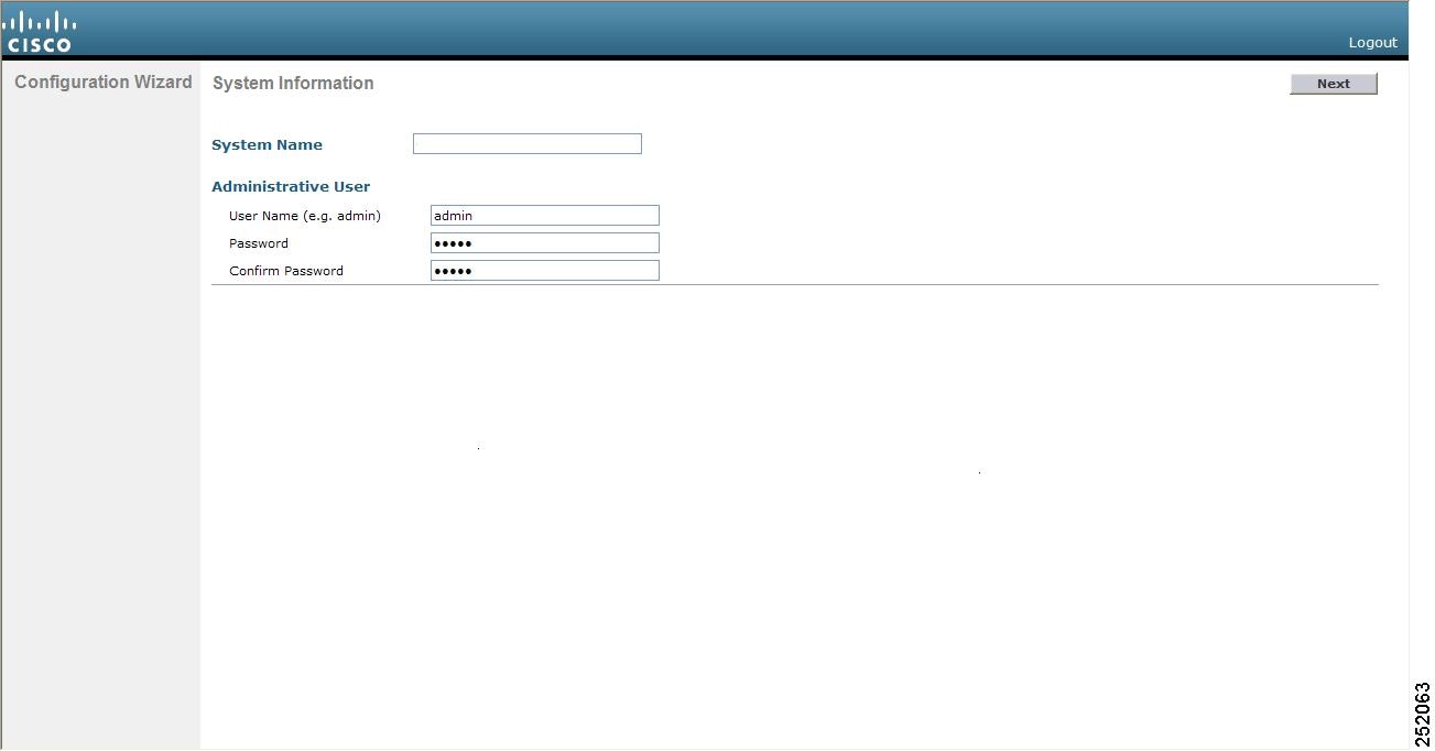
| Step 3 | In the System Name box, enter the name that you want to assign to this Cisco WLC. You can enter up to 31 ASCII characters. | ||||
| Step 4 | In the User Name box, enter the administrative username to be assigned to this Cisco WLC. You can enter up to 24 ASCII characters. The default username is admin. | ||||
| Step 5 | In the
Password and
Confirm Password boxes, enter the administrative
password to be assigned to this Cisco WLC. You can enter up to 24 ASCII
characters. The default password is
admin.
Starting in release 7.0.116.0, the following password policy has been implemented:
| ||||
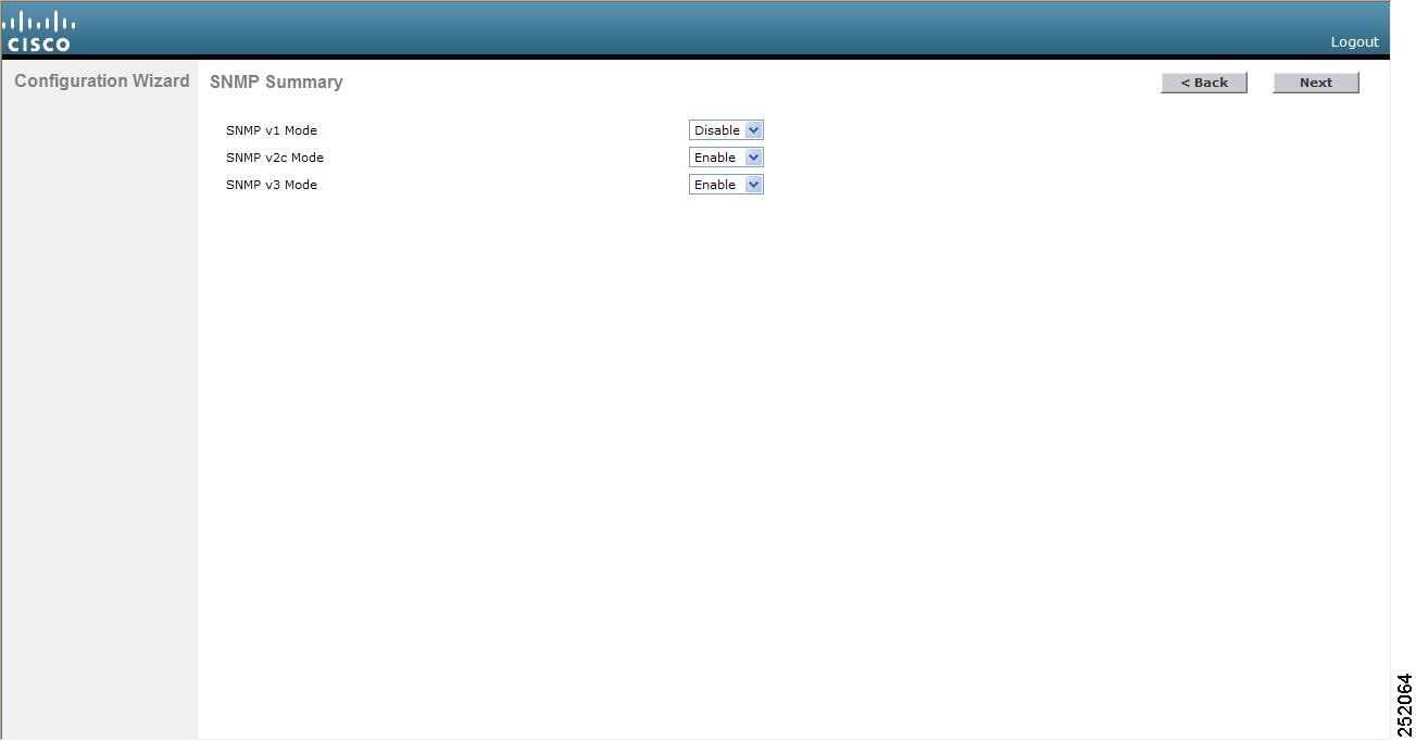
| Step 6 | Click
Next. The
SNMP
Summary page is displayed.
| ||||
| Step 7 | If you want to
enable Simple Network Management Protocol (SNMP) v1 mode for this Cisco WLC,
choose
Enable from the
SNMP
v1 Mode drop-down list. Otherwise, leave this parameter set to
Disable.
| ||||
| Step 8 | If you want to enable SNMPv2c mode for this Cisco WLC, leave this parameter set to Enable. Otherwise, choose Disable from the SNVP v2c Mode drop-down list. | ||||
| Step 9 | If you want to enable SNMPv3 mode for this Cisco WLC, leave this parameter set to Enable. Otherwise, choose Disable from the SNVP v3 Mode drop-down list. | ||||
| Step 10 | Click Next. | ||||
| Step 11 | When the
following message appears, click
OK:
Default values are present for v1/v2c community strings.
Please make sure to create new v1/v2c community strings once the system comes up.
Please make sure to create new v3 users once the system comes up.
The Service Interface Configuration page is displayed.
| ||||
| Step 12 | If you want the
Cisco WLC’s service-port interface to obtain an IP address from a DHCP server,
check the
DHCP Protocol
Enabled check box. If you do not want to use the service port or if
you want to assign a static IP address to the service port, leave the check box
unchecked.
| ||||
| Step 13 | Perform one of the following: | ||||
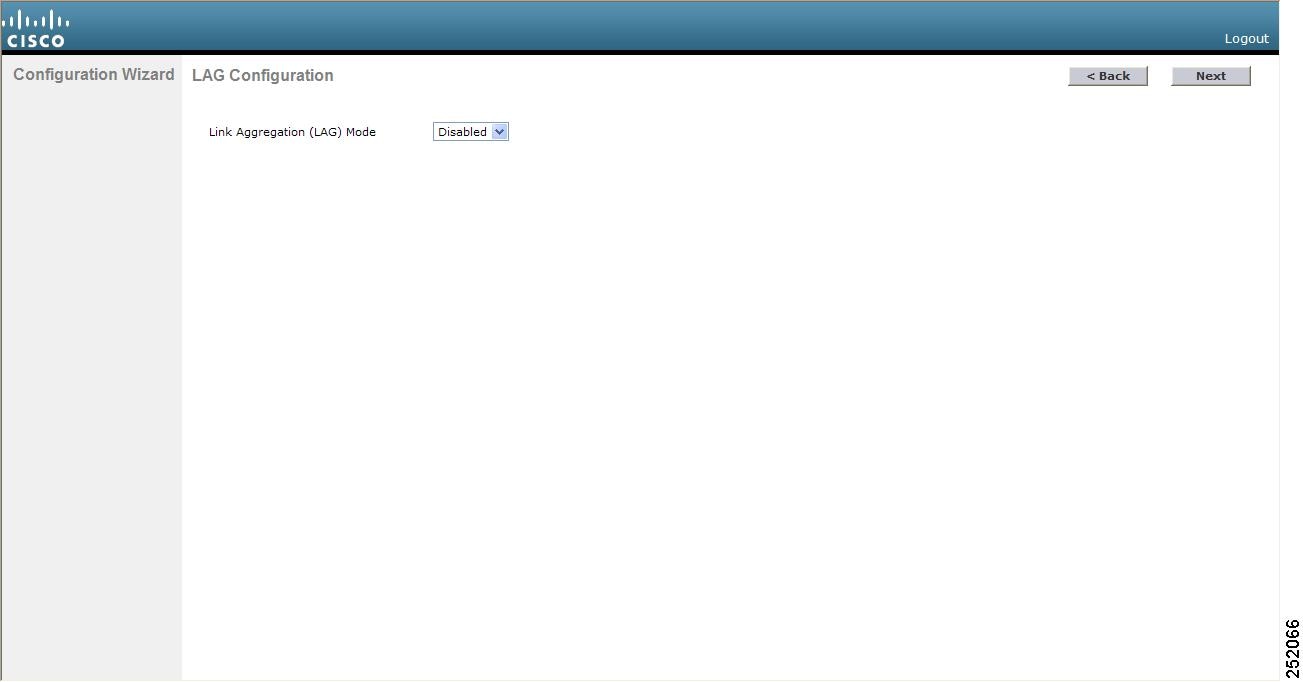
| Step 14 | Click
Next.
The LAG Configuration page is displayed.
| ||||
| Step 15 | To enable link aggregation (LAG), choose Enabled from the Link Aggregation (LAG) Mode drop-down list. To disable LAG, leave this text box set to Disabled. | ||||
| Step 16 | Click
Next.
The Management Interface Configuration page is displayed.
| ||||
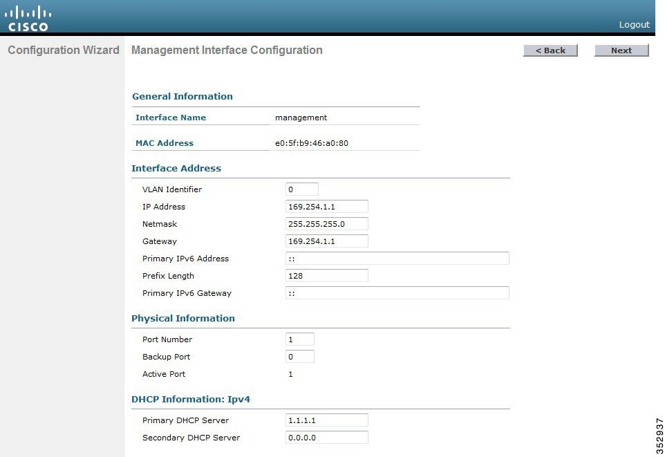
| Step 17 | In the VLAN Identifier box, enter the VLAN identifier of the management interface (either a valid VLAN identifier or 0 for an untagged VLAN). The VLAN identifier should be set to match the switch interface configuration. | ||||
| Step 18 | In the IP Address box, enter the IP address of the management interface. | ||||
| Step 19 | In the Netmask box, enter the IP address of the management interface netmask. | ||||
| Step 20 | In the Gateway box, enter the IP address of the default gateway. | ||||
| Step 21 | In the Port Number box, enter the number of the port assigned to the management interface. Each interface is mapped to at least one primary port. | ||||
| Step 22 | In the Backup Port box, enter the number of the backup port assigned to the management interface. If the primary port for the management interface fails, the interface automatically moves to the backup port. | ||||
| Step 23 | In the Primary DHCP Server box, enter the IP address of the default DHCP server that will supply IP addresses to clients, the controller’s management interface, and optionally, the service port interface. | ||||
| Step 24 | In the Secondary DHCP Server box, enter the IP address of an optional secondary DHCP server that will supply IP addresses to clients, the controller’s management interface, and optionally, the service port interface. | ||||
| Step 25 | Click
Next. The
AP-Manager Interface Configuration page is
displayed.
| ||||
| Step 26 | In the IP Address box, enter the IP address of the AP-manager interface. | ||||
| Step 27 | Click
Next. The
Miscellaneous Configuration page is displayed.
| ||||
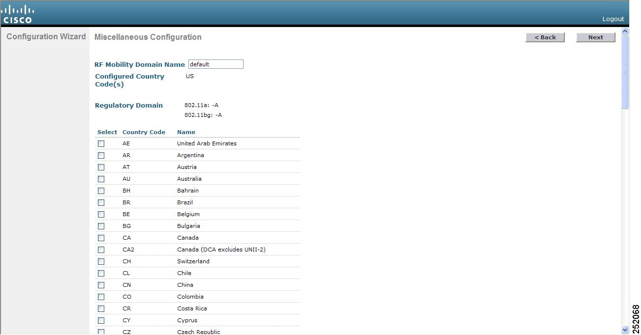
| Step 28 | In the
RF
Mobility Domain Name box, enter the name of the mobility group/RF
group to which you want the controller to belong.
| ||||
| Step 29 | The
Configured Country Code(s) box shows the code for
the country in which the controller will be used. If you want to change the
country of operation, check the check box for the desired country.
| ||||
| Step 30 | Click Next. | ||||
| Step 31 | When the
following message appears, click
OK:
Warning! To maintain regulatory compliance functionality, the country code
setting may only be modified by a network administrator or qualified IT professional.
Ensure that proper country codes are selected before proceeding.?
The Virtual Interface Configuration page is displayed. | ||||
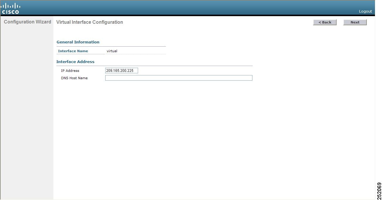
| Step 32 | In the
IP
Address box, enter the IP address of the Cisco WLC’s virtual
interface. You should enter a fictitious, unassigned IP address.
| ||||
| Step 33 | In the
DNS
Host Name box, enter the name of the Domain Name System (DNS)
gateway used to verify the source of certificates when Layer 3 web
authorization is enabled.
| ||||
| Step 34 | Click
Next. The
WLAN
Configuration page is displayed.
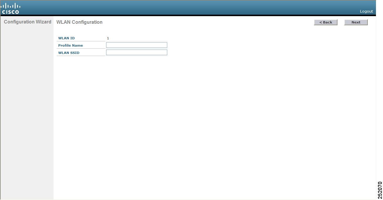 | ||||
| Step 35 | In the Profile Name box, enter up to 32 alphanumeric characters for the profile name to be assigned to this WLAN. | ||||
| Step 36 | In the WLAN SSID box, enter up to 32 alphanumeric characters for the network name, or service set identifier (SSID). The SSID enables basic functionality of the Cisco WLC and allows access points that have joined the controller to enable their radios. | ||||
| Step 37 | Click Next. | ||||
| Step 38 | When the
following message appears, click
OK:
Default Security applied to WLAN is: [WPA2(AES)][Auth(802.1x)]. You can change this after the wizard is complete and the system is rebooted.?
The RADIUS Server Configuration page is displayed.  | ||||
| Step 39 | In the Server IP Address box, enter the IP address of the RADIUS server. | ||||
| Step 40 | From the
Shared Secret Format drop-down list, choose
ASCII or
Hex to specify the format of the shared secret.
| ||||
| Step 41 | In the Shared Secret and Confirm Shared Secret boxes, enter the secret key used by the RADIUS server. | ||||
| Step 42 | In the Port Number box, enter the communication port of the RADIUS server. The default value is 1812. | ||||
| Step 43 | To enable the RADIUS server, choose Enabled from the Server Status drop-down list. To disable the RADIUS server, leave this box set to Disabled. | ||||
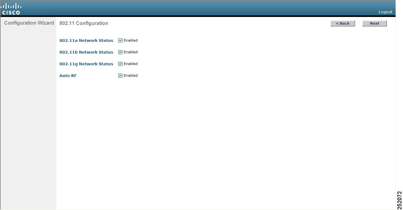
| Step 44 | Click
Apply. The
802.11 Configuration page is displayed.
| ||||
| Step 45 | To enable the 802.11a, 802.11b, and 802.11g lightweight access point networks, leave the 802.11a Network Status, 802.11b Network Status, and 802.11g Network Status check boxes checked. To disable support for any of these networks, uncheck the check boxes. | ||||
| Step 46 | To enable the controller’s radio resource management (RRM) auto-RF feature, leave the
Auto RF check box selected. To disable support for the auto-RF feature, uncheck this check box.
| ||||
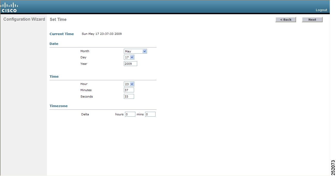
| Step 47 | Click
Next. The
Set Time page is displayed.
| ||||
| Step 48 | To manually configure the system time on your controller, enter the current date in Month/DD/YYYY format and the current time in HH:MM:SS format. | ||||
| Step 49 | To manually set the time zone so that Daylight Saving Time (DST) is not set automatically, enter the local hour difference from Greenwich Mean Time (GMT) in the
Delta Hours box and the local minute difference from GMT in the
Delta Mins box.
| ||||
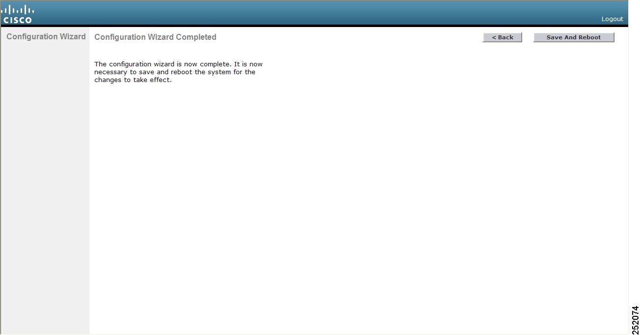
| Step 50 | Click
Next. The
Configuration Wizard Completed page is displayed.
| ||||
| Step 51 | Click Save and Reboot to save your configuration and reboot the Cisco WLC. | ||||
| Step 52 | When the following message appears, click
OK:
			 Configuration will be saved and the controller will be
				rebooted. Click ok to confirm.?
The Cisco WLC saves your configuration, reboots, and prompts you to log on. |

Configuring the Controller—Using the CLI Configuration Wizard
-
The available options appear in brackets after each configuration parameter. The default value appears in all uppercase letters.
-
If you enter an incorrect response, the controller provides you with an appropriate error message, such as “Invalid Response,” and returns you to the wizard prompt.
-
Press the hyphen key if you ever need to return to the previous command line.
| Step 1 | When prompted to terminate the AutoInstall
process, enter
yes. If you do not enter
yes, the AutoInstall
process begins after 30 seconds.
| ||||
| Step 2 | Enter the system name, which is the name that you want to assign to the controller. You can enter up to 31 ASCII characters. | ||||
| Step 3 | Enter the administrative
username and password to be assigned to this controller. You can enter up to 24
ASCII characters for each.
Starting in release 7.0.116.0, the following password policy has been implemented:
| ||||
| Step 4 | If you want the
controller’s service-port interface to obtain an IP address from a DHCP server,
enter
DHCP. If you do not want
to use the service port or if you want to assign a static IP address to the
service port, enter none.
| ||||
| Step 5 | If you entered none in Step 4, enter the IP address and netmask for the service-port interface on the next two lines. | ||||
| Step 6 | Enable or disable link aggregation (LAG) by choosing yes or NO. | ||||
| Step 7 | Enter the IP
address of the management interface.
| ||||
| Step 8 | Enter the IP address of the management interface netmask. | ||||
| Step 9 | Enter the IP address of the default router. | ||||
| Step 10 | Enter the VLAN identifier of the management interface (either a valid VLAN identifier or 0 for an untagged VLAN). The VLAN identifier should be set to match the switch interface configuration. | ||||
| Step 11 | Enter the IP
address of the default DHCP server that will supply IP addresses to clients,
the management interface of the controller, and optionally, the service port
interface. Enter the IP address of the AP-manager interface.
| ||||
| Step 12 | Enter the IP
address of the controller’s virtual interface. You should enter a fictitious
unassigned IP address.
| ||||
| Step 13 | If desired,
enter the name of the mobility group/RF group to which you want the controller
to belong.
| ||||
| Step 14 | Enter the network name or service set identifier (SSID). The SSID enables basic functionality of the controller and allows access points that have joined the controller to enable their radios. | ||||
| Step 15 | Enter YES to allow clients to assign their own IP address or no to require clients to request an IP address from a DHCP server. | ||||
| Step 16 | To configure a RADIUS server now, enter YES and then enter the IP address, communication port, and secret key of the RADIUS server. Otherwise, enter no. If you enter no, the following message appears: “Warning! The default WLAN security policy requires a RADIUS server. Please see the documentation for more details.” | ||||
| Step 17 | Enter the code
for the country in which the controller will be used.
| ||||
| Step 18 | Enable or disable the 802.11b, 802.11a, and 802.11g lightweight access point networks by entering YES or no. | ||||
| Step 19 | Enable or
disable the controller’s radio resource management (RRM) auto-RF feature by
entering
YES or
no.
| ||||
| Step 20 | If you want the
controller to receive its time setting from an external Network Time Protocol
(NTP) server when it powers up, enter
YES to configure an NTP
server. Otherwise, enter
no.
| ||||
| Step 21 | If you entered no in Step 20 and want to manually configure the system time on your controller now, enter YES. If you do not want to configure the system time now, enter no. | ||||
| Step 22 | If you entered YES in Step 21, enter the current date in the MM/DD/YY format and the current time in the HH:MM:SS format. After you have completed step 22, the wizard prompts you to configure IPv6 parameters. Enter yes to proceed. | ||||
| Step 23 | Enter the service port interface IPv6 address configuration. You can enter either static or SLAAC. | ||||
| Step 24 | Enter the IPv6 address of the management interface. | ||||
| Step 25 | Enter the IPv6 address prefix length of the management interface. | ||||
| Step 26 | Enter the gateway IPv6 address of the management interface . Once the management interface configuration is complete, the wizard prompts to configure IPv6 parameters for RADIUS server. Enter yes. | ||||
| Step 27 | Enter the IPv6 address of the RADIUS server. | ||||
| Step 28 | Enter the communication port number of the RADIUS server. The default value is 1812. | ||||
| Step 29 | Enter the secret key for IPv6 address of the RADIUS server. Once the RADIUS server configuration is complete, the wizard prompts to configure IPv6 NTP server. Enter yes. | ||||
| Step 30 | Enter the IPv6 address of the NTP server. | ||||
| Step 31 | When prompted to
verify that the configuration is correct, enter
yes or
NO.
The Cisco WLC saves your configuration when you enter yes, reboots, and prompts you to log on. |
Using the AutoInstall Feature for Controllers Without a Configuration
This section describes how to use the AutoInstall feature for controllers without a configuration.
Information About the AutoInstall Feature
When you boot up a controller that does not have a configuration, the AutoInstall feature can download a configuration file from a TFTP server and then load the configuration onto the controller automatically.
If you create a configuration file on a controller that is already on the network (or through a Prime Infrastructure filter), place that configuration file on a TFTP server, and configure a DHCP server so that a new controller can get an IP address and TFTP server information, the AutoInstall feature can obtain the configuration file for the new controller automatically.
When the controller boots, the AutoInstall process starts. The controller does not take any action until AutoInstall is notified that the configuration wizard has started. If the wizard has not started, the controller has a valid configuration.
If AutoInstall is notified that the configuration wizard has started (which means that the controller does not have a configuration), AutoInstall waits for an additional 30 seconds. This time period gives you an opportunity to respond to the first prompt from the configuration wizard:
Would you like to terminate autoinstall? [yes]:
When the 30-second abort timeout expires, AutoInstall starts the DHCP client. You can abort the AutoInstall task even after this 30-second timeout if you enter Yes at the prompt. However, AutoInstall cannot be aborted if the TFTP task has locked the flash and is in the process of downloading and installing a valid configuration file.
Note | The AutoInstall process and manual configuration using both the GUI and CLI of Cisco WLC can occur in parallel. As part of the AutoInstall cleanup process, the service port IP address is set to 192.168.1.1 and the service port protocol configuration is modified. Because the AutoInstall process takes precedence over the manual configuration, whatever manual configuration is performed is overwritten by the AutoInstall process. |
Restrictions on AutoInstall
- Obtaining an IP Address Through DHCP and Downloading a Configuration File from a TFTP Server
- Selecting a Configuration File
- Example: AutoInstall Operation
Obtaining an IP Address Through DHCP and Downloading a Configuration File from a TFTP Server
AutoInstall attempts to obtain an IP address from the DHCP server until the DHCP process is successful or until you abort the AutoInstall process. The first interface to successfully obtain an IP address from the DHCP server registers with the AutoInstall task. The registration of this interface causes AutoInstall to begin the process of obtaining TFTP server information and downloading the configuration file.
Following the acquisition of the DHCP IP address for an interface, AutoInstall begins a short sequence of events to determine the host name of the controller and the IP address of the TFTP server. Each phase of this sequence gives preference to explicitly configured information over default or implied information and to explicit host names over explicit IP addresses.
If at least one Domain Name System (DNS) server IP address is learned through DHCP, AutoInstall creates a /etc/resolv.conf file. This file includes the domain name and the list of DNS servers that have been received. The Domain Name Server option provides the list of DNS servers, and the Domain Name option provides the domain name.
If the domain servers are not on the same subnet as the controller, static route entries are installed for each domain server. These static routes point to the gateway that is learned through the DHCP Router option.
The host name of the controller is determined in this order by one of the following:
If the DHCP Host Name option was received, this information (truncated at the first period [.]) is used as the host name for the controller.
A reverse DNS lookup is performed on the controller IP address. If DNS returns a hostname, this name (truncated at the first period [.]) is used as the hostname for the controller.
The IP address of the TFTP server is determined in this order by one of the following:
If AutoInstall received the DHCP TFTP Server Name option, AutoInstall performs a DNS lookup on this server name. If the DNS lookup is successful, the returned IP address is used as the IP address of the TFTP server.
If the DHCP Server Host Name (sname) text box is valid, AutoInstall performs a DNS lookup on this name. If the DNS lookup is successful, the IP address that is returned is used as the IP address of the TFTP server.
If AutoInstall received the DHCP TFTP Server Address option, this address is used as the IP address of the TFTP server.
AutoInstall performs a DNS lookup on the default TFTP server name (cisco-wlc-tftp). If the DNS lookup is successful, the IP address that is received is used as the IP address of the TFTP server.
If the DHCP server IP address (siaddr) text box is nonzero, this address is used as the IP address of the TFTP server.
The limited broadcast address (255.255.255.255) is used as the IP address of the TFTP server.
If the TFTP server is not on the same subnet as the controller, a static route (/32) is installed for the IP address of the TFTP server. This static route points to the gateway that is learned through the DHCP Router option.
Selecting a Configuration File
After the hostname and TFTP server have been determined, AutoInstall attempts to download a configuration file. AutoInstall performs three full download iterations on each interface that obtains a DHCP IP address. If the interface cannot download a configuration file successfully after three attempts, the interface does not attempt further.
The first configuration file that is downloaded and installed successfully triggers a reboot of the controller. After the reboot, the controller runs the newly downloaded configuration.
AutoInstall searches for configuration files in the order in which the names are listed:
AutoInstall runs through this list until it finds a configuration file. It stops running if it does not find a configuration file after it cycles through this list three times on each registered interface.
Note | The downloaded configuration file can be a complete configuration, or it can be a minimal configuration that provides enough information for the controller to be managed by the Cisco Prime Infrastructure. Full configuration can then be deployed directly from the Prime Infrastructure. |
Note | AutoInstall does not expect the switch connected to the controller to be configured for either channels. AutoInstall works with a service port in LAG configuration. |
Note | Cisco Prime Infrastructure provides AutoInstall capabilities for controllers. A Cisco Prime Infrastructure administrator can create a filter that includes the host name, the MAC address, or the serial number of the controller and associate a group of templates (a configuration group) to this filter rule. The Prime Infrastructure pushes the initial configuration to the controller when the controller boots up initially. After the controller is discovered, the Prime Infrastructure pushes the templates that are defined in the configuration group. For more information about the AutoInstall feature and Cisco Prime Infrastructure, see the Cisco Prime Infrastructure documentation. |
Example: AutoInstall Operation
The following is an example of an AutoInstall process from start to finish:
Welcome to the Cisco Wizard Configuration Tool
Use the '-' character to backup
Would you like to terminate autoinstall? [yes]:
AUTO-INSTALL: starting now...
AUTO-INSTALL: interface 'service-port' - setting DHCP TFTP Filename ==> 'abcd-confg'
AUTO-INSTALL: interface 'service-port' - setting DHCP TFTP Server IP ==> 1.100.108.2
AUTO-INSTALL: interface 'service-port' - setting DHCP siaddr ==> 1.100.108.2
AUTO-INSTALL: interface 'service-port' - setting DHCP Domain Server[0] ==> 1.100.108.2
AUTO-INSTALL: interface 'service-port' - setting DHCP Domain Name ==> 'engtest.com'
AUTO-INSTALL: interface 'service-port' - setting DHCP yiaddr ==> 172.19.29.253
AUTO-INSTALL: interface 'service-port' - setting DHCP Netmask ==> 255.255.255.0
AUTO-INSTALL: interface 'service-port' - setting DHCP Gateway ==> 172.19.29.1
AUTO-INSTALL: interface 'service-port' registered
AUTO-INSTALL: interation 1 -- interface 'service-port'
AUTO-INSTALL: DNS reverse lookup 172.19.29.253 ===> 'wlc-1'
AUTO-INSTALL: hostname 'wlc-1'
AUTO-INSTALL: TFTP server 1.100.108.2 (from DHCP Option 150)
AUTO-INSTALL: attempting download of 'abcd-confg'
AUTO-INSTALL: TFTP status - 'TFTP Config transfer starting.' (2)
AUTO-INSTALL: interface 'management' - setting DHCP file ==> 'bootfile1'
AUTO-INSTALL: interface 'management' - setting DHCP TFTP Filename ==> 'bootfile2-confg'
AUTO-INSTALL: interface 'management' - setting DHCP siaddr ==> 1.100.108.2
AUTO-INSTALL: interface 'management' - setting DHCP Domain Server[0] ==> 1.100.108.2
AUTO-INSTALL: interface 'management' - setting DHCP Domain Server[1] ==> 1.100.108.3
AUTO-INSTALL: interface 'management' - setting DHCP Domain Server[2] ==> 1.100.108.4
AUTO-INSTALL: interface 'management' - setting DHCP Domain Name ==> 'engtest.com'
AUTO-INSTALL: interface 'management' - setting DHCP yiaddr ==> 1.100.108.238
AUTO-INSTALL: interface 'management' - setting DHCP Netmask ==> 255.255.254.0
AUTO-INSTALL: interface 'management' - setting DHCP Gateway ==> 1.100.108.1
AUTO-INSTALL: interface 'management' registered
AUTO-INSTALL: TFTP status - 'Config file transfer failed - Error from server: File not found' (3)
AUTO-INSTALL: attempting download of 'wlc-1-confg'
AUTO-INSTALL: TFTP status - 'TFTP Config transfer starting.' (2)
AUTO-INSTALL: TFTP status - 'TFTP receive complete... updating configuration.' (2)
AUTO-INSTALL: TFTP status - 'TFTP receive complete... storing in flash.' (2)
AUTO-INSTALL: TFTP status - 'System being reset.' (2)
Resetting system
Managing the Controller System Date and Time
This section describes how to manage the date and time of a controller system.
- Information About Controller System Date and Time
- Restrictions on Configuring the Cisco WLC Date and Time
- Configuring the Date and Time (GUI)
- Configuring the Date and Time (CLI)
Information About Controller System Date and Time
You can configure the controller system date and time at the time of configuring the controller using the configuration wizard. If you did not configure the system date and time through the configuration wizard or if you want to change your configuration, you can follow the instructions in this section to configure the controller to obtain the date and time from a Network Time Protocol (NTP) server or to configure the date and time manually. Greenwich Mean Time (GMT) is used as the standard for setting the time zone on the controller.
You can also configure an authentication mechanism between various NTP servers.
Restrictions on Configuring the Cisco WLC Date and Time
-
If you are configuring wIPS, you must set the controller time zone to UTC.
-
Cisco Aironet lightweight access points might not connect to the controller if the date and time are not set properly. Set the current date and time on the controller before allowing the access points to connect to it.
-
You can configure an authentication channel between the controller and the NTP server.
Configuring the Date and Time (GUI)
| Step 1 | Choose
Commands > Set Time to open the
Set Time page.
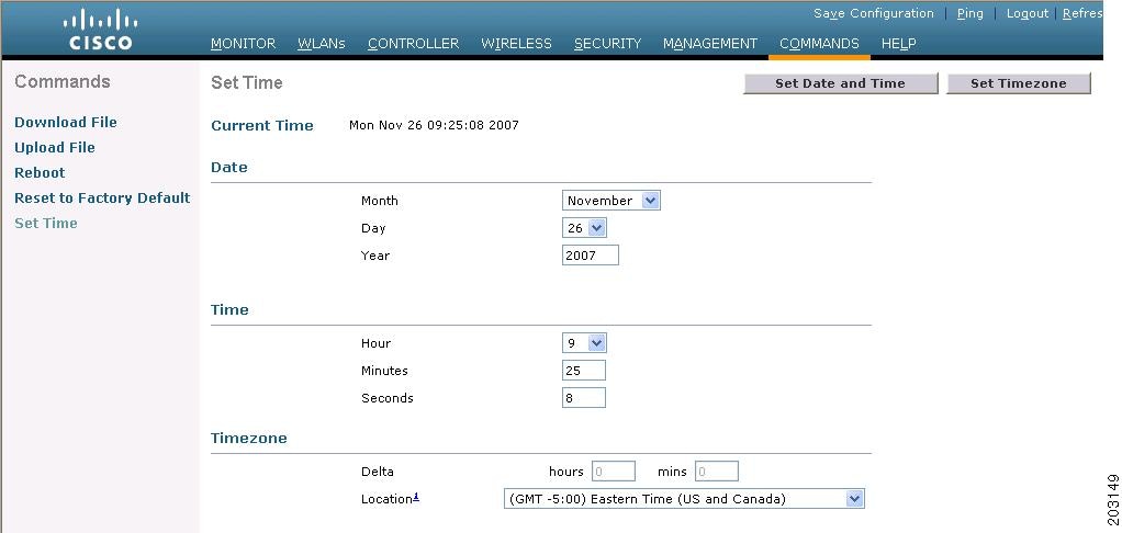 | ||||
| Step 2 | In the
Timezone area, choose your local time zone
from the
Location drop-down list.
| ||||
| Step 3 | Click Set Timezone to apply your changes. | ||||
| Step 4 | In the Date area, choose the current local month and day from the Month and Day drop-down lists, and enter the year in the Year box. | ||||
| Step 5 | In the
Time area, choose the current local hour from
the
Hour drop-down list, and enter the minutes and
seconds in the
Minutes and
Seconds boxes.
| ||||
| Step 6 | Click Set Date and Time to apply your changes. | ||||
| Step 7 | Click Save Configuration. |
Configuring the Date and Time (CLI)
| Step 1 | Configure the current local date and time in GMT on the controller by entering this command: config time manual mm/dd/yy hh:mm:ss
| ||||
| Step 2 | Perform one of the following to set the time zone for the controller:
| ||||
| Step 3 | Save your changes by entering this command: | ||||
| Step 4 | Verify that the controller shows the current local time with respect to the local time zone by entering this command:
Information similar to the following appears: Time.................................... Thu Apr 7 13:56:37 2011 Timezone delta........................... 0:0 Timezone location....................... (GMT +5:30) Colombo, New Delhi, Chennai, Kolkata NTP Servers NTP Polling Interval......................... 3600 Index NTP Key Index NTP Server NTP Msg Auth Status ------- --------------------------------------------------------------- 1 1 209.165.200.225 AUTH SUCCESS
|
 Feedback