Contents
- Chassis Installation
- Mounting Options
- Weight Considerations
- Unpacking the Chassis
- Move the Container to the Installation Site
- Unpack the Chassis
- Reducing the Weight of the Chassis Prior to Installation
- Removing the Fan Trays
- Remove the Upper Front Fan Tray
- Remove the Lower Front Fan Tray
- Remove the Upper Rear Fan Tray
- Remove the Lower Rear Fan Tray
- Removing the PFUs
- Installing the Chassis
- Mounting the Chassis
- Flush Mount
- Mid Mount
- Grounding the Chassis
- Ground Cabling
- Grounding Procedure
- Re-Installing Chassis Components
- Re-install the PFUs
- Re-install the Front Fan Trays
- Lower Front Fan Tray
- Upper Front Fan Tray
- Re-install the Rear Fan Trays
- Lower Rear Fan Tray
- Upper Rear Fan Tray
- Re-install the Chassis Cover Panels
- Front of Chassis
- Rear of Chassis
- Cable Management System
Chassis Installation
- Mounting Options
- Weight Considerations
- Unpacking the Chassis
- Reducing the Weight of the Chassis Prior to Installation
- Installing the Chassis
- Grounding the Chassis
- Re-Installing Chassis Components
- Cable Management System
Mounting Options
Flush mount: In this configuration, the flanges of the mounting brackets are flush with the front of the chassis. This is the default configuration as shipped. This method is typically used to mount the chassis in a 4-post rack or equipment cabinet. Refer to
Mid-mount: In this configuration, the flanges of the mounting brackets are recessed from the front of the chassis. To do this, the mounting brackets must be removed and reinstalled toward the middle of the chassis. This method is typically used to mount the chassis in a two-post rack. Refer to
Weight Considerations
-
If available, use an equipment lift to move the chassis and position it into the rack/cabinet.
-
If a lift is not available, reduce the weight of the chassis by following the instructions in Reducing the Weight of the Chassis Prior to Installation.
-
Remove all obstructions in the path from the delivery location to the rack/cabinet.
-
At least two people should perform the installation. These individuals should be physically able to lift and control the weight of the chassis.
-
When lifting any heavy object, remember to bend at the knees and lift with your legs. Bending at the waist and lifting with your back could cause personal injury.
The ASR 5500 chassis is shipped with no circuit cards installed. Only the PFUs, fan trays and air filters are installed. The circuit cards are shipped in separate cartons.
 Caution | If you are mounting two chassis in a single rack, verify that the rack is rated to handle the combined, fully loaded weight of both chassis and any ancillary equipment. |
Unpacking the Chassis
The ASR 5500 chassis is shipped on a palletized container.
The front and rear circuit cards are packaged and shipped in separate cartons.
Locate the packing list for the shipment and verify that all components have been received.
Safely store the shipping container and its components in case the chassis must be shipped to another site or returned for repair.
Move the Container to the Installation Site
Before unpacking the chassis, use a pallet jack to move the container as close to the final installation site as possible. The cardboard cap and sleeve will protect the chassis from damage when moving the container.
Height = 50 in. (127 cm)
Width = 24 in. (61 cm)
Depth = 32 in. (81.3 cm) [width on the pallet forks]
Weight = 265 lbs (120.2 kg)
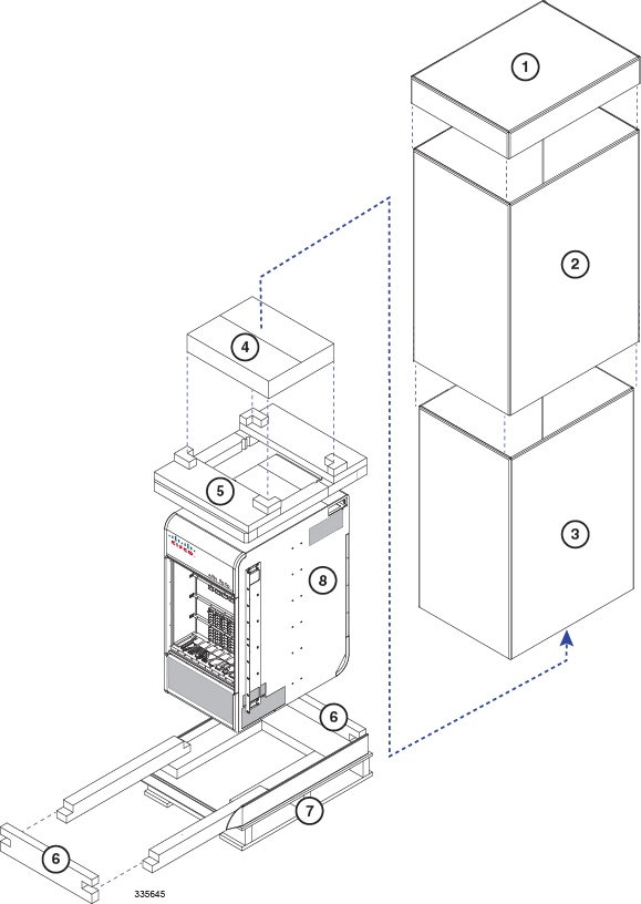
Unpack the Chassis
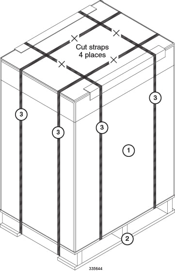
Caution | You should wear protective gloves and safety glasses when handling the shipping crate banding while unpacking the system. The straps that connect the packaging material are capable of inflicting damage to your skin or eyes if not handled properly. |
| Step 1 | Cut the straps that secure the cap and card board sleeve to the pallet. Remove the straps from the pallet and discard. |
| Step 2 | Remove the cardboard cap from the top of the container. |
| Step 3 | Lift the outer cardboard sleeve up and over the top of the chassis. |
| Step 4 | Lift the inner cardboard sleeve up and over the top of the chassis. |
| Step 5 | Remove the accessory box. This box contains miscellaneous hardware items and spare air filters. |
| Step 6 | Remove the foam cap from the top of the chassis. |
| Step 7 | Remove the bottom front and rear end caps from the base of the chassis. |
| Step 8 | Remove the plastic bag that covers the chassis. |
| Step 9 | If you will be removing chassis components to reduce the weight of the chassis, leave the chassis on the pallet and proceed to Reducing the Weight of the Chassis Prior to Installation |
| Step 10 | Use a chassis lift or multiple craftpersons to lift or slide the chassis off the shipping pallet. Proceed to Installing the Chassis. |
Reducing the Weight of the Chassis Prior to Installation
You can reduce the weight of the chassis prior to installation by removing the upper and lower fan trays, and the PFUs. Follow the instructions below to safely remove these components prior to installation.
Caution | During installation, maintenance and/or removal, wear a grounding wrist strap to avoid ESD damage to the components. Connect the strap to a ground point on the rack/cabinet frame. Failure to do so could result in damage to sensitive electronic components and potentially void your warranty. |
Removing the Fan Trays
Caution | To avoid personal injury and/or damage to the fan trays, be sure to support each fan tray's weight from its front and rear as you slide it completely out of the chassis. |
- Remove the Upper Front Fan Tray
- Remove the Lower Front Fan Tray
- Remove the Upper Rear Fan Tray
- Remove the Lower Rear Fan Tray
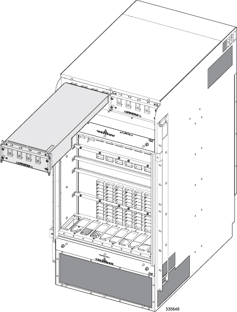
Remove the Upper Front Fan Tray
Remove the Lower Front Fan Tray
| Step 1 | Remove the cover panel from the bottom of the chassis. Firmly grasp the side edges of the panel and pull down and away to unsnap the panel. Put the panel safely aside. |
| Step 2 | Use a #1 Phillips screwdriver to loosen the screws and remove the access panel from the lower-front of the chassis. Place it safely aside. |
| Step 3 | Loosen the two screws on the fan tray. |
| Step 4 | Grasp the center pull on the front of the fan tray and pull. The fan tray should unseat from the midplane connector and slide out of the chassis. |
| Step 5 | Place the fan tray safely aside. |
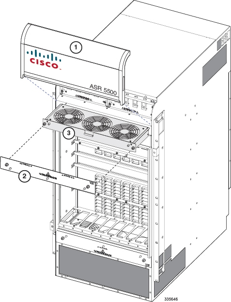
Remove the Upper Rear Fan Tray
| Step 1 | At the rear of the chassis, remove the cover panel from the top of the chassis just below the vent panel. Firmly grasp the side edges of the panel and pull up and away to unsnap the panel. Put the panel safely aside. |
| Step 2 | Loosen the screws and remove the upper fan tray access panel from the chassis. Place it safely aside. |
| Step 3 | Use a #1 Phillips screwdriver to loosen the two screws that secure the handle to the front of the fan tray. |
| Step 4 | Flip up and grasp the fan tray handle and pull. The fan tray should unseat from the midplane connector and slide out of the chassis. Support the bottom of the fan tray unit with one hand as you pull it away from the chassis. |
| Step 5 | Place the fan tray unit safely aside. |
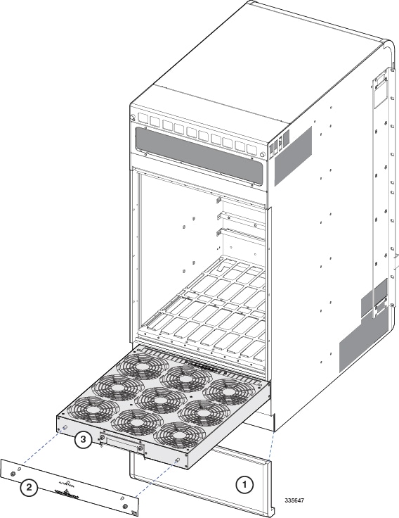
Remove the Lower Rear Fan Tray
Removing the PFUs
Installing the Chassis
If you are installing more than one chassis in an equipment rack, install the first chassis at the bottom of the rack.
Caution | When handling or moving the chassis, lift the chassis from the bottom only. Lifting it by any other part could damage the chassis. |
Caution | During installation, maintenance and/or removal, wear a grounding wrist strap to avoid ESD damage to the components. Connect the strap to a ground point on the rack/cabinet frame. Failure to do so could result in damage to sensitive electronic components and potentially void your warranty. |
Mounting the Chassis
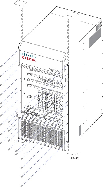
Flush Mount
| Step 1 | Position the chassis in the equipment rack so that the flanges of the mounting brackets at the front of the chassis are flush with the mounting rails of the equipment rack. |
| Step 2 | Mount the chassis to the rack rails using the OEM hardware that was supplied with the equipment rack. Begin with the two bottom holes and work your way up until all holes on each flange are secured. |
| Step 3 | Repeat step 1 and step 2 if you are installing an additional chassis in the equipment rack/cabinet. |
| Step 4 | If you took steps to reduce the weight of the chassis prior to installation, refer to Re-Installing Chassis Components. Otherwise, proceed to Grounding the Chassis. |
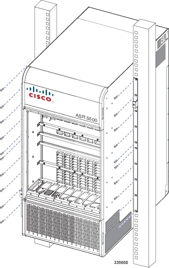
Mid Mount
| Step 1 | On the side of the chassis, use a Phillips #2 screwdriver to remove the twelve flathead screws that secure the mounting bracket to the chassis. |
| Step 2 | Place the mounting bracket over the middle set of mounting holes on the side of the chassis and secure it to the chassis with the screws you removed in step 1. |
| Step 3 | Repeat step 1 and step 2 and reposition the bracket on the opposite side of the chassis. |
| Step 4 | Position the chassis in the equipment rack so that the flanges of the mounting brackets are flush with the mounting rails of the equipment rack. |
| Step 5 | Mount the chassis to the rack rails using the OEM hardware that was supplied with the equipment rack. Begin with the two bottom holes and work your way up until all holes on each flange are secured. |
| Step 6 | If you took steps to reduce the weight of the chassis prior to installation, refer to Re-Installing Chassis Components. Otherwise, proceed to Grounding the Chassis. |
Grounding the Chassis
The chassis must be properly grounded prior to installing any chassis components or cards. The chassis and the equipment rack/cabinet must be connected to the same ground point.
Caution | Failure to properly ground the chassis could result in personal injury and/or damage to the chassis and its components. |
There are two sets of grounding terminals located at the lower-rear of the chassis. Figure 4-8 shows the location of these terminals and provides specifications for the appropriate lug and cable size.
Ground Cabling
The ASR 5500 is suitable for installation as part of the Common Bonding Network (CBN) in a network telecommunications facility. It is not intended for installation in an Isolated Bonding Network (IBN).
A 2-hole lug (Panduit LCD4-14A-L) is supplied for grounding the chassis. The lug must be crimped to the end of a ground cable using Panduit crimp tool part number CT-720-1 (die color: gray, P29). The wire strip length is 7/8-inch (22 mm),
The minimum, recommended stranded cable size is 4 AWG. the cable length to the site ground point should not exceed 70 feet (21 m) one way.
The method of connection is: chassis -> lug -> flat washer -> nut (7/16-inch).
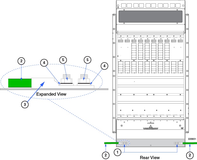
Grounding Procedure
| Step 1 | Remove the rear bottom cover from the chassis. Grasp both sides of the cover and pull out and up to unsnap the cover. |
| Step 2 | Locate the ground terminal on the lower-left corner at the rear of the chassis. |
| Step 3 | Use a 7/16-inch nut driver or socket wrench to remove the Kep nuts and washers from each post. |
| Step 4 | Insert the lug connected to the grounding cable over the two posts. |
| Step 5 | Secure the lug to the ground terminals with the Kep nuts and washers you removed in step 2. The nuts should be torqued to 50 in-lb (5.65 N-m). |
| Step 6 | Repeat step 2 through step 5 to connect the ground cable to the grounding posts on the lower-right corner at the rear of the chassis. |
| Step 7 | If you took steps to reduce the weight of the chassis prior to installation, refer to the instructions in Re-Installing Chassis Components. Otherwise, proceed to the Card Installation chapter. |
Re-Installing Chassis Components
If you removed chassis components to reduce the weight of the chassis, re-install the components by completing the following the procedures.
Caution | During installation, maintenance, and/or removal, wear a grounding wrist strap connected to the ASR 5500 chassis to avoid ESD damage to the components. Failure to do so could result in damage to sensitive electronic components and potentially void your warranty. |
- Re-install the PFUs
- Re-install the Front Fan Trays
- Re-install the Rear Fan Trays
- Re-install the Chassis Cover Panels
Re-install the PFUs
Re-install the Front Fan Trays
Lower Front Fan Tray
| Step 1 | At the front of the chassis, align the fan tray within the lower chassis opening. With the unit resting on the bottom rail of the opening, push inward until it is seated in the midplane. |
| Step 2 | Use a #1 Phillips screwdriver to tighten the two captive screws that secure the fan tray to the chassis. |
| Step 3 | Reinstall the lower access cover. |
Upper Front Fan Tray
| Step 1 | Align the fan tray within the upper chassis opening. With the unit resting on the bottom rail of the opening, push inward until it is seated in the midplane. |
| Step 2 | Use a #1 Phillips screwdriver to tighten the two captive screws that secure the fan tray to the chassis. |
| Step 3 | Reinstall the upper access cover. |
Re-install the Rear Fan Trays
Lower Rear Fan Tray
| Step 1 | At the rear of the chassis, align the fan tray within the opening at the bottom rear of the chassis. |
| Step 2 | With the unit resting on the bottom rail of the opening, slowly slide the fan tray into the chassis along the guides until it is seated firmly in the midplane connectors. |
| Step 3 | Reinstall the lower access cover. |
Upper Rear Fan Tray
| Step 1 | Align the fan tray within the opening at the upper rear of the chassis. |
| Step 2 | With the unit resting on the bottom rail of the opening, slowly slide the fan tray into the chassis along the guides until it is seated firmly in the midplane connectors. |
| Step 3 | Reinstall the upper access cover. |
Re-install the Chassis Cover Panels
Front of Chassis
| Step 1 | Reinstall the top cover panel by aligning the cover over the balled posts on the fan tray access panel and above the PDF bays. Push inwards to snap it in place. |
| Step 2 | Reinstall the bottom cover panel by aligning the cover over the balled posts on the fan tray access panel and below the air intake panel. Push inwards to snap it in place. |
Rear of Chassis
| Step 1 | Reinstall the top cover panel by aligning the cover over the balled posts on the fan tray access panel. Push inwards to snap it in place. |
| Step 2 | Reinstall the bottom cover panel by aligning the cover over the balled posts on the fan tray access panel and below the ground terminals. Push inwards to snap it in place. |
Cable Management System
The ASR 5500 chassis ships with a cable management tray. This tray can be used in conjunction with cable management brackets that mount on the MIO/UMIO cards to route and secure network cables to interface ports.
Installation of the cable management system is optional.
Refer to the Cable Management System Installation appendix for additional information.