Contents
- Cable Management System Installation
- Introduction
- Installing the Cable Management Tray
- Removing Cable Guides
- Installing Cable Management Brackets
- MIO/UMIO Cards
- Securing Cables
- Routing and Securing Network Cables
- CMS Procedure for Replacing ASR 5500 Circuit Cards
- Lowering the Cable Management Tray
- Detaching Network Cables from the Card Bracket
- Reconnecting Network Cables to the Card Bracket
- Raising the Cable Management Tray
Cable Management
System Installation
- Introduction
- Installing the Cable Management Tray
- Removing Cable Guides
- Installing Cable Management Brackets
- Routing and Securing Network Cables
- CMS Procedure for Replacing ASR 5500 Circuit Cards
Introduction
The ASR 5500 cable management system consists of two components. The first is a tray that mounts at the rear of the chassis immediately below the card cage. The second is a cable management bracket that mounts to the faceplate of each MIO/UMIO card.
Network cables are fed from the ends of the tray and are then routed to the MIO/UMIO ports. The cables are secured to the cable management brackets on the MIO/UMIOs via cable ties or hook-and-loop straps, and within the cable management tray via hook-and-loop straps. Placing the tray in the closed (upright) position protects the cables from damage.
Installing the Cable Management Tray
The cable management tray is packaged in the accessory box that is included in the ASR 5500 chassis shipping container.
When installed and closed, the cable management tray adds 4.5 in. (11.4 cm) to the depth of the chassis. When lowered, the tray adds 6.0 in. (15.2 cm) to the depth.
Having two installers simplifies the installation process. One installer holds the tray in position while the other secures the swing arms to the sides of the chassis.
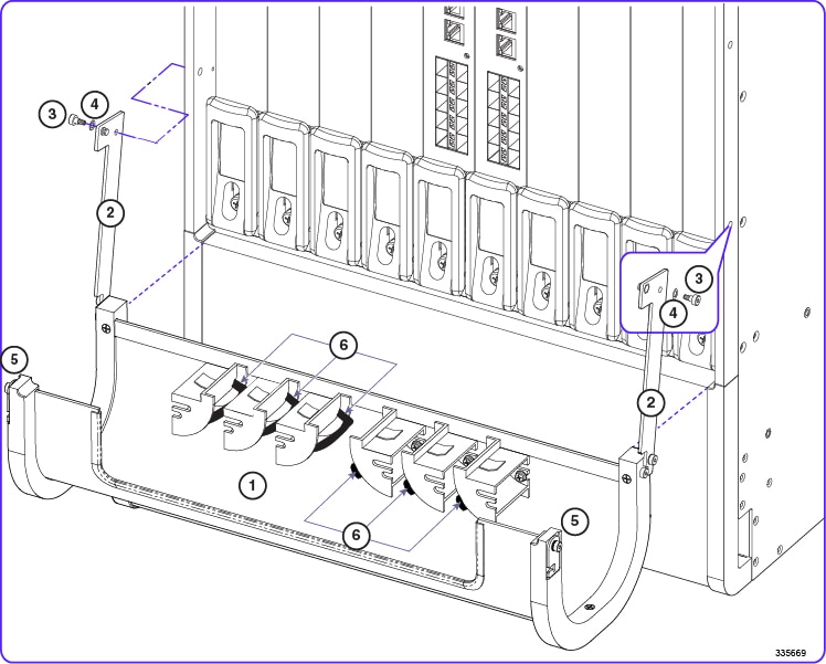
To install the tray:
| Step 1 | Locate the pre-assembled tray and its mounting hardware (two shoulder screws and two nylon washers). |
| Step 2 | Position the tray below the rear card cage as shown in the figure below. |
| Step 3 | Lift a swing arm upward and use it to locate the tapped hole in the side of the chassis to which the swing arm will be attached (see the figure below). |
| Step 4 | Insert the shoulder screw and nylon washer through the arm and into the tapped hole. |
| Step 5 | Use the supplied
3/32 in. Allen hex wrench to tighten the shoulder screw. The screw should be
tightened to 6 in-lb (0.68 N-m).
Important:
Do not overtighten the shoulder screw or the swing arm will bind. |
| Step 6 | Repeat Step 3 through Step 5 to secure the other swing arm. |
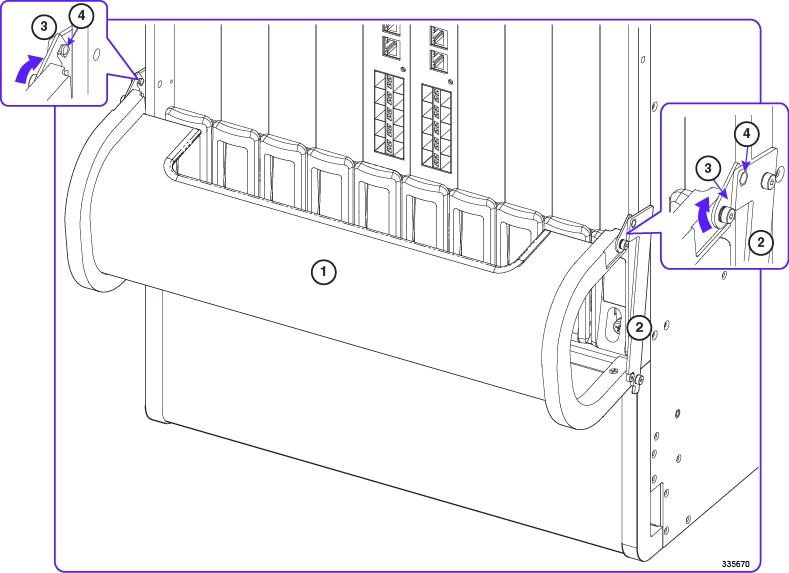
| Step 7 | Verify that the tray can be swung upward into its closed position. Test the latches by clipping them to the posts on the swing arms. You may need to apply slight inward pressure on the latches so they will clear the swing arms and rest on the posts. See the figure below. To lower the cable management tray, unlatch the swing arms and lift the base of the tray slightly upward before allowing it to swing downwards. This completes the installation of the cable management tray. To gain improved access to the hook-and-loop straps on the cable guides, refer to Removing Cable Guides. You must install the cable management bracket on each MIO/UMIO card before you can route and secure network cables. For additional information, refer to Installing Cable Management Brackets. |
Removing Cable Guides
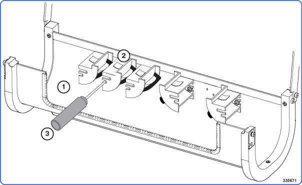
To gain additional space for accessing the hook-and-loop straps in the cable tray, you may remove the middle cable guides from the left and right side of the tray.
You will need a Phillips #1 screwdriver for this procedure.
To remove a cable guide:
Installing Cable Management Brackets
The cable management bracket is packaged in the MIO/UMIO shipping box.
Ideally, the bracket should be installed on an MIO/UMIO before it is installed in the ASR 5500 chassis. However, you can safely install the bracket on an MIO/UMIO in a powered-up ASR 5500 chassis.
No tools are required to install the bracket on an MIO/UMIO card.
 Caution | Observe ESD precautions when handling the MIO/UMIO. Wear a ground strap connected to the ESD jack located at the upper left corner of the chassis. |
MIO/UMIO Cards
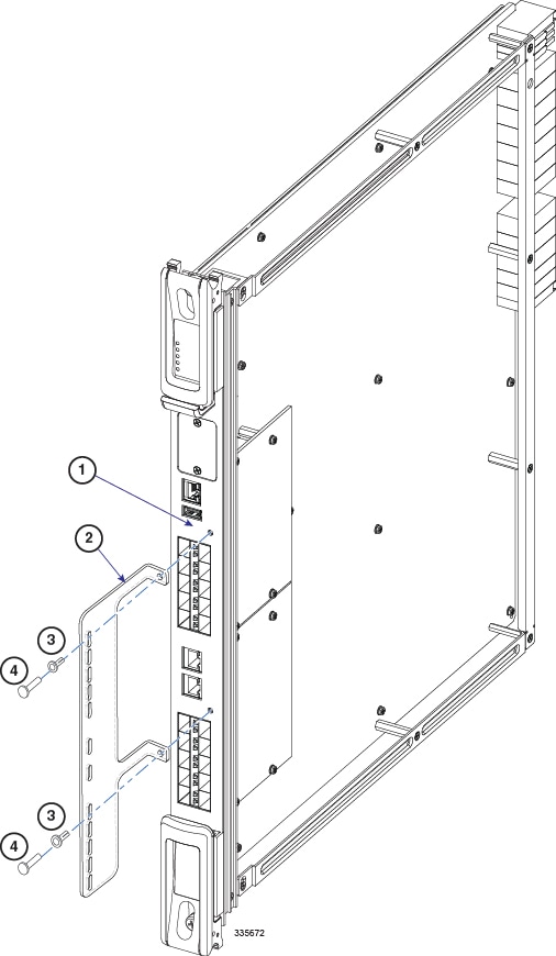
| Step 1 | Locate the bracket and its mounting hardware (two nylon pin-and-sleeve connectors). | ||||||||||
| Step 2 | Position the bracket on the faceplate of the MIO/UMIO as shown in the figure below. | ||||||||||
| Step 3 | Insert a nylon sleeve in both holes of the bracket and into the MIO/UMIO faceplate. | ||||||||||
| Step 4 | Use your thumb
to firmly push a nylon pin into each sleeve to secure the bracket to the
faceplate.
|
Securing Cables
This completes the installation of the cable management bracket. You can use cable ties or hook-and-loop straps to secure network cables to the slots in the bracket. For additional information, refer to Routing and Securing Network Cables.
Routing and Securing Network Cables
This procedure assumes that the cable management tray has been installed on the ASR 5500 chassis, and cable management brackets have been installed on the MIO/UMIO cards.
The general procedure for using the CMS is to route network cables through either end of the cable management tray upwards toward the cable management brackets on the MIO/UMIOs.
-
Label each cable with its terminating slot/port number,
-
Insert SFP+ transceivers in all 10 GbE ports that will receive cables.
-
Use the cable guides on the left side of the tray for cables going to the MIO/UMIO in slot 5, and on the right side of the tray for the MIO/UMIO in slot 6.
-
Open the hook-and-loop straps on the cable guides nearest the MIO/UMIOs before routing cables.
-
Begin by routing cables that attach at the bottom of the MIO/UMIO and proceed upward from the bottom daughter card (DC) to the top DC.
-
Slip the cables beneath the cable guides and loop them upward and within the straps along the curved edges of the guides.
-
Keep fiber optic cables going to even number ports to the left of the bracket, odd number ports to the right. Use cable guide A or D for the odd ports, and cable guide B/C or E/F for the even number ports (see the figure below).
-
Firmly seat each cable connector into its port.
-
Thread nylon cable ties or hook-and-loop straps through the slots in the cable management brackets. Use the ties/straps to secure the cables to the brackets.
-
Observe the fiber optic bending radius recommendations found in the MIO Cabling chapter.
-
Complete the process of securing the cables by closing the hook-and-loop straps on the cable guides. Leave a little slack in the cables to allow the tray to close without pinching the cables.
-
For additional support of cable bundles, slip a nylon cable tie or hook-and-loop strap under the clip at the top of a cable guide and wrap it around the bundle.
Verify that the cable tray can be lifted upward and secured without pinching any of the network cables. If necessary increase the slack in a bundle to avoid damaging the cables.
The figure and table below show the recommended sequence for routing cables to the MIO/UMIOs in slots 5 and 6.

| 1 | Cable management bracket | 2 | Cable management tray |
| 3 | Cable guides | ||
| Card | Cable Guide | Notes | Destination |
|---|---|---|---|
| MIO or UMIO, slot 5 | 3A | — | Bottom DC (ports 20 to 29) |
| 3A | — | 1GbE (ports 1 and 2) | |
| 3B or 3C | 1 | Top DC (ports 10 to 19) | |
| 3C | 2 | Future | |
| MIO or UMIO, slot 6 | 3D | — | Bottom DC (ports 20 to 29) |
| 3D | — | 1GbE (ports 1 and 2) | |
| 3E or 3F | 1 | Top DC (ports 10 to 19) | |
| 3F | 2 | Future |
- If cable guide has been removed.
- Already in use if cable guide has been removed.
CMS Procedure for Replacing ASR 5500 Circuit Cards
When the cable management tray is installed, the procedure for removing circuit cards from the ASR 5500 chassis varies from that described in the Circuit Cards section of the Replaceable Components chapter.
- Lowering the Cable Management Tray
- Detaching Network Cables from the Card Bracket
- Reconnecting Network Cables to the Card Bracket
- Raising the Cable Management Tray
Lowering the Cable Management Tray
| Step 1 | At the rear of the chassis, apply slight upward pressure at the base of the cable management tray. |
| Step 2 | Flip the latches on the swing arms upward and free of the posts. |
| Step 3 | Lower the tray until it rests against the chassis. |
| Step 4 | If you are removing an MIO/UMIO card, refer to Detaching Network Cables from the Card Bracket. Otherwise, remove the circuit card as described in the Remove and Replace the Circuit Card section of the Replaceable Components chapter. |
| Step 5 | Proceed to Raising the Cable Management Tray. |
Detaching Network Cables from the Card Bracket
| Step 1 | Cut the nylon cable ties or open the hook-and-loop straps that secure network cables to the MIO/UMIO card. | ||
| Step 2 | Unplug the cable
connectors starting from the top ports.
Important:
The ends of all network cables should be labeled with their slot/port terminations. If this has not been done, you should label each cable as you disconnect it. | ||
| Step 3 | Move the cable bundles away from the MIO/UMIO. You may have to re-open the hook-and-loop straps in the cable management tray to free the cables. | ||
| Step 4 | Remove the
MIO/UMIO card as described in
Remove and
Replace the Circuit Card section of the
Replaceable
Components chapter.
|
Reconnecting Network Cables to the Card Bracket
| Step 1 | The replacement MIO/UMIO card should have a cable management bracket pre-installed as described in Installing Cable Management Brackets |
| Step 2 | Route the cables and secure them to the bracket as described in Routing and Securing Network Cables |
| Step 3 | Proceed to Raising the Cable Management Tray |
Raising the Cable Management Tray
| Step 1 | Grasp the base and slowly raise the cable management tray upward. |
| Step 2 | Verify that the cable tray can be lifted upward and secured without pinching any of the network cables. If necessary increase the slack in a bundle to avoid damaging the cables. |
| Step 3 | Flip the latches on the swing arms up and over the posts to secure the tray to the chassis. |