Table Of Contents
Configuring the Access Point/Bridge for the First Time
Resetting the Access Point/Bridge to Default Settings
Using the Web-Browser Interface
Obtaining and Assigning an IP Address
Connecting to the Access Point/Bridge Locally
Default Settings on the Express Setup Page
Configuring Basic Security Settings
Understanding Express Security Settings
Using the Express Security Page
Using IPSU to Find the Access Point/Bridge's IP Address
Using IPSU to Set the Access Point/Bridge's IP Address and SSID
Assigning an IP Address Using the CLI
Using a Telnet Session to Access the CLI
Using the Console Port to Access the CLI
Configuring the Access Point/Bridge for the First Time
This chapter describes how to configure basic settings on your access point/bridge for the first time. You can configure all the settings described in this chapter using the CLI, but it might be simplest to browse to the access point/bridge's web-browser interface to complete the initial configuration and then use the CLI to enter additional settings for a more detailed configuration.
This chapter contains these sections:
•Obtaining and Assigning an IP Address
•Configuring Basic Security Settings
•Assigning an IP Address Using the CLI
•Using a Telnet Session to Access the CLI
•Using the Console Port to Access the CLI
Before You Start
Before you install the access point/bridge, make sure you are using a computer connected to the same network as the access point/bridge, and obtain the following information from your network administrator:
•A system name for the access point/bridge
•The case-sensitive wireless service set identifier (SSID) that your access point/bridges use
•If not connected to a DHCP server, a unique IP address for your access point/bridge (such as 172.17.255.115)
•If the access point/bridge is not on the same subnet as your PC, a default gateway address and subnet mask
•A Simple Network Management Protocol (SNMP) community name and the SNMP file attribute (if SNMP is in use)
•If you use IPSU to find or assign the access point/bridge IP address, the MAC address from the product label on the access point/bridge (such as 00164625854c)
Resetting the Access Point/Bridge to Default Settings
You can use the web-browser interface or the CLI to reset the access point/bridge to a factory default configuration.
Note The following steps reset all configuration settings to factory defaults, including passwords, WEP keys, the IP address, and the SSID.
Using the Web-Browser Interface
Follow the steps below to delete the current configuration and return all access point/bridge settings to the factory defaults using the Web-browser interface.
Step 1 Open your Internet browser.
Step 2 Enter the access point/bridge's IP address in the browser address or location line and press Enter. An Enter Network Password screen appears.
Step 3 Enter your username (default Cisco) in the User Name field.
Step 4 Enter the access point/bridge password (default Cisco) in the Password field and press Enter. The Summary Status page appears.
Step 5 Click System Software and the System Software screen appears.
Step 6 Click System Configuration and the System Configuration screen appears.
Step 7 Click Default.
Note If the access point/bridge is configured with a static IP address, the IP address does not change.
Step 8 After the access point/bridge reboots, you can reconfigure the access point/bridge by using the Web-browser interface or the CLI (refer to the Cisco IOS Software Configuration Guide for Cisco Aironet Bridges or to the Cisco IOS Software Configuration Guide for Cisco Aironet Access Points).
Using the CLI
From the privileged EXEC mode, you can reset the access point/bridge configuration to factory default values using the CLI by following these steps:
Step 1 Enter erase nvram: to erase all NVRAM files including the startup configuration.
Step 2 Enter Y when the following CLI message displays: Erasing the nvram filesystem will remove all configuration files! Continue? [confirm].
Step 3 Enter reload when the following CLI message displays: Erase of nvram: complete. This command reloads the operating system.
Step 4 Enter Y when the following CLI message displays: Proceed with reload? [confirm].
Caution Do not interrupt the boot process to avoid damaging the configuration file. Wait until the access point/bridge Install Mode LED begins to blink green before continuing with CLI configuration changes. You can also see the following CLI message when the load process has finished: Line protocal on Interface Dot11Radio0, changed state to up.
Step 5 After the access point/bridge reboots, you can reconfigure the access point/bridge by using the Web-browser interface or the CLI.
The access point/bridge is configured with the factory default values including the IP address (set to receive an IP address using DHCP). To obtain the access point/bridge's new IP address, you can use the show interface bvi1 CLI command. If the access point/bridge does not receive an IP address from a DHCP server, the access point/bridge IP address is 10.0.0.1.
Obtaining and Assigning an IP Address
To browse to the access point/bridge's Express Setup page, you must either obtain or assign the access point/bridge's IP address using one of the following methods:
•Use default address 10.0.0.1 when you connect to the access point/bridge locally. For detailed instructions, see the "Connecting to the Access Point/Bridge Locally" section.
•Use a DHCP server (if available) to automatically assign an IP address. You can find out the DHCP-assigned IP address using one of the following methods:
–Provide your organization's network administrator with your access point/bridge's Media Access Control (MAC) address. Your network administrator will query the DHCP server using the MAC address to identify the IP address. The access point/bridge's MAC address is on the label attached to the bottom of the access point/bridge.
–Use the Cisco IP Setup Utility (IPSU) to identify the assigned address. You can also use IPSU to assign an IP address to the access point/bridge if it did not receive an IP address from the DHCP server. IPSU runs on most Microsoft Windows operating systems: Windows 9x, 2000, Me, NT, and XP.
You can download IPSU from the Software Center on Cisco.com. Click this link to browse to the Software Center:
http://www.cisco.com/cisco/software/navigator.html
–If the unit is a non-root bridge, browse to the Associations page on the root bridge to which the non-root is associated. The non-root bridge's MAC address and IP address appear on the root bridge's Associations page.
Connecting to the Access Point/Bridge Locally
If you need to configure the access point/bridge locally (without connecting the access point/bridge to a wired LAN), you can connect a PC to the Ethernet port on the long-reach power injector using a Category 5 Ethernet cable. You can use a local connection to the power injector's Ethernet port much as you would use a serial port connection.
Note You do not need a special crossover cable to connect your PC to the power injector; you can use either a straight-through cable or a crossover cable.
If the access point/bridge is configured with default values and not connected to a DHCP server or cannot obtain an IP address, it defaults to IP address 10.0.0.1. When a non-root bridge associates to a root bridge, it receives an IP address from the root bridge. Browse to the Associations page on the root bridge to find the non-root bridge's IP address, or use IPSU to find the IP address.
Follow these steps to connect to the bridge locally:
Step 1 Make sure that the PC you intend to use is configured to obtain an IP address automatically, or manually assign it an IP address from 10.0.0.2 to 10.0.0.10.
Step 2 With the power cable disconnected from the power injector, connect your PC to the power injector using a Category 5 Ethernet cable. You can use either a crossover cable or a straight-through cable.
Step 3 Connect the power injector to the access point/bridge using dual coaxial cables.
Step 4 Connect the power injector power cable and power up the access point/bridge.
Step 5 Follow the steps in the "Assigning Basic Settings" section. If you make a mistake and need to start over, follow the steps in the "Resetting the Access Point/Bridge to Default Settings" section.
Step 6 After configuring the access point/bridge, remove the Ethernet cable from your PC and connect the power injector to your wired LAN.
Note When you connect your PC to the access point/bridge or reconnect your PC to the wired LAN, you might need to release and renew the IP address on the PC. On most PCs, you can perform a release and renew by rebooting your PC or by entering ipconfig /release and ipconfig /renew commands in a command prompt window. Consult your PC operating instructions for detailed instructions.
Assigning Basic Settings
After you determine or assign the access point/bridge's IP address, you can browse to the access point/bridge's Express Setup page and perform an initial configuration:
Step 1 Open your Internet browser. The access point/bridge web-browser interface is fully compatible with these browsers: Microsoft Internet Explorer versions 5.0, 5.01, 5.5 and 6.0; and Netscape Navigator versions 4.79 and 7.0.
Step 2 Enter the access point/bridge's IP address in the browser address line and press Enter. An Enter Network Password screen appears.
Step 3 Press Tab to bypass the Username field and advance to the Password field.
Step 4 Enter the case-sensitive password Cisco and press Enter. The Summary Status page appears. Figure 2-1 shows the Summary Status page.
Figure 2-1 Summary Status Page
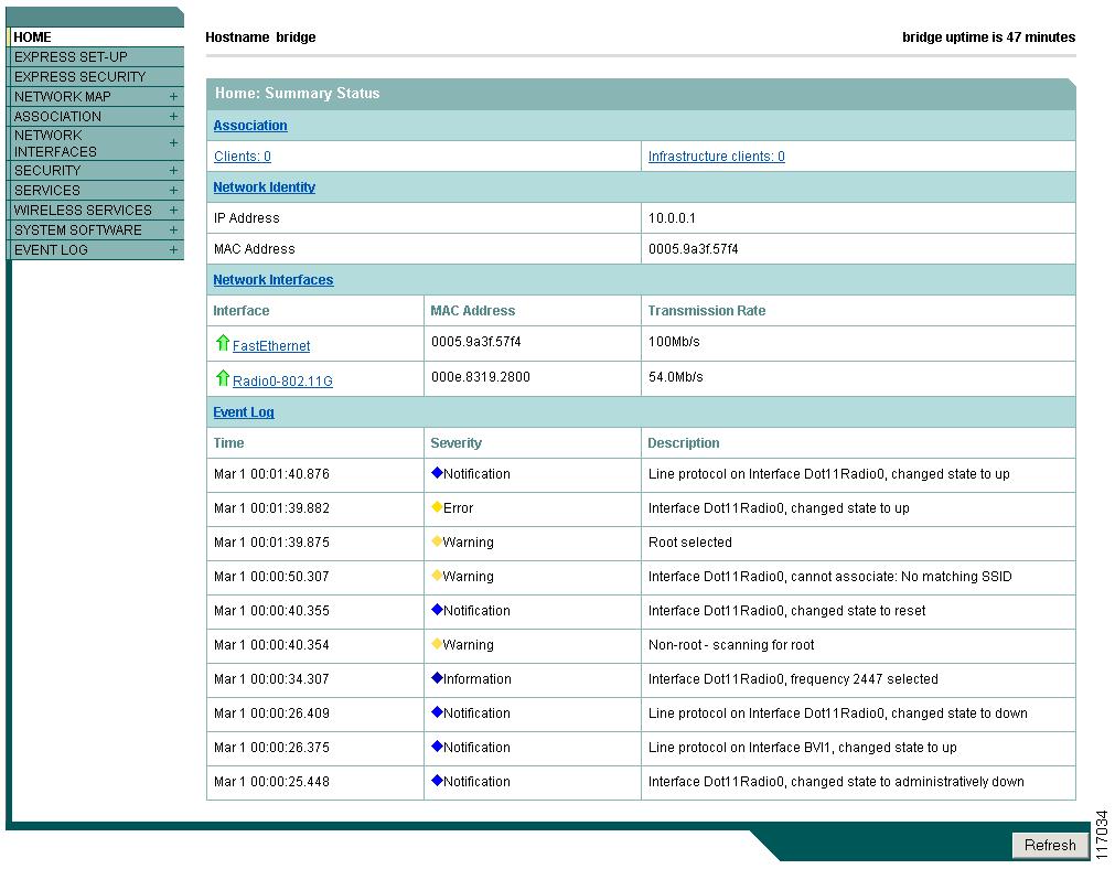
Step 5 Click Express Setup. The Express Setup screen appears. Figure 2-2 shows the Express Setup page.
Figure 2-2 Express Setup Page
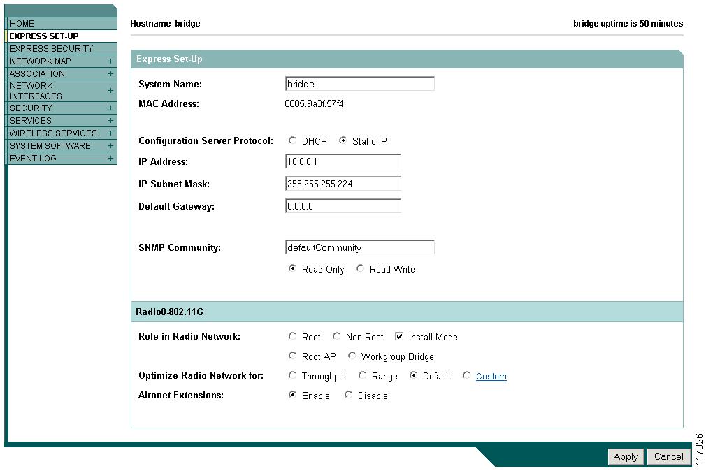
Step 6 Enter the configuration settings you obtained from your system administrator. The configurable settings include:
•System Name— The system name, while not an essential setting, helps identify the access point/bridge on your network. The system name appears in the titles of the management system pages.
•Configuration Server Protocol—Click on the button that matches the network's method of IP address assignment.
–DHCP—IP addresses are automatically assigned by your network's DHCP server.
–Static IP—The access point/bridge uses a static IP address that you enter in the IP address field.
•IP Address—Use this setting to assign or change the access point/bridge's IP address. If DHCP is enabled for your network, leave this field blank.
Note If the access point/bridge's IP address changes while you are configuring the access point/bridge using the web-browser interface or a Telnet session over the wired LAN, you lose your connection to the access point/bridge. If you lose your connection, reconnect to the access point/bridge using its new IP address. Follow the steps in the "Resetting the Access Point/Bridge to Default Settings" section if you need to start over.
•IP Subnet Mask—Enter the IP subnet mask provided by your network administrator so the IP address can be recognized on the LAN. If DHCP is enabled, leave this field blank.
•Default Gateway—Enter the default gateway IP address provided by your network administrator. If DHCP is enabled, leave this field blank.
•SNMP Community—If your network is using SNMP, enter the SNMP Community name provided by your network administrator and select the attributes of the SNMP data (also provided by your network administrator).
•Role in Radio Network—Click on the button that describes the role of the access point/bridge on your network.
–Root—Configures the access point/bridge as a root access point/bridge. In this mode, you establish a link with a non-root access point/bridge. In this mode, the access point/bridge also accepts associations from clients.
–Non-Root— Places the access point/bridge in non-root mode. In this mode, it links with a root access point/bridge.
–Install Mode—Places the access point/bridge into installation mode so you can align and adjust a bridge link for optimum efficiency.
Note Install Mode is the access point/bridge's default setting for the Role in Radio Network parameter.
–Root AP—Places the access point/bridge in the access point mode. In this mode, the access point/bridge emulates a Cisco Aironet 1100 Series Access Point and accepts associations from client devices.
–Workgroup Bridge—Places the access point/bridge in the workgroup bridge mode. In this mode, the access point/bridge emulates the Cisco Aironet 350 Series Workgroup Bridge and accepts wired clients.
Note In bridge modes, one bridge in any pair or group of bridges must be set to root, and the bridge or bridges associated to the root bridge must be set to non-root.
•Optimize Radio Network for—Use this setting to select either preconfigured settings for the access point/bridge radio or customized settings for the access point/bridge radio. See the "Configuring the Radio Distance Setting" section on page 6-11 for more information on data rates and throughput.
–Throughput—Maximizes the data volume handled by the access point/bridge but might reduce its range. When you select Throughput, the access point/bridge sets all data rates to basic.
–Range—Maximizes the access point/bridge's range but might reduce throughput. When you select Range, the access point/bridge sets the 6-Mbps rate to basic and the other rates to enabled.
–Default—The access point/bridge retains default radio settings that are designed to provide good range and throughput for most access point/bridges.
–Custom—Takes you to the Network Interfaces: Radio-802.11G Settings page. The access point/bridge uses settings you enter on this page.
•Aironet Extensions—This setting is always enabled on 1300 series access point/bridges.
Step 7 Click Apply to save your settings. If you changed the IP address, you lose your connection to the access point/bridge. Browse to the new IP address to reconnect to the access point/bridge.
Your access point/bridge is now running but probably requires additional configuring to conform to your network's operational and security requirements.
Default Settings on the Express Setup Page
Table 2-1 lists the default settings for the settings on the Express Setup page.
Protecting Your Wireless LAN
After you assign basic settings to your access point/bridge, you must configure security settings to prevent unauthorized access to your network. Because it is a radio device, the access point/bridge can communicate beyond the physical boundaries of your building. You can use Express Security page in the Configuring Basic Security Settings section to set basic security settings for your access point/bridge. Advanced security features can be found in the following chapters:
•A unique SSID that are not broadcast in the access point/bridge beacon (see Chapter 7, "Configuring SSIDs"
•WEP and WEP features (see Chapter 9, "Configuring WEP and WEP Features")
•Dynamic WEP and access point/bridge authentication (see Chapter 10, "Configuring Authentication Types")
Configuring Basic Security Settings
After you assign basic settings to your access point, you must configure security settings to prevent unauthorized access to your network. Because it is a radio device, the access point can communicate beyond the physical boundaries of your worksite.
Just as you use the Express Setup page to assign basic settings, you can use the Express Security page to create unique SSIDs and assign one of four security types to them. Figure 2-3 shows the Express Security page.
Figure 2-3 Express Security Page
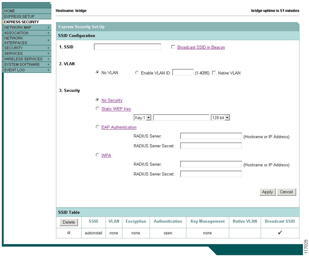
The Express Security page helps you configure basic security settings. You can use the web-browser interface's main Security pages to configure more advanced security settings.
Understanding Express Security Settings
When the access point/bridge configuration is at factory defaults, the first SSID that you create using the Express security page overwrites the default SSID, install, which has no security settings. The SSIDs that you create appear in the SSID table at the bottom of the page. You can create up to 16 SSIDs on the access point.
Using VLANs
If you use VLANs on your wireless LAN and assign SSIDs to VLANs, you can create multiple SSIDs using any of the four security settings on the Express Security page. However, if you do not use VLANs on your wireless LAN, the security options that you can assign to SSIDs are limited because, on the Express Security page, encryption settings and authentication types are linked. Without VLANs, encryption settings (WEP and ciphers) apply to an interface such as the 2.4-GHz radio, and you cannot use more than one encryption setting on an interface. For example, when you create an SSID with static WEP with VLANs disabled, you cannot create additional SSIDs with WPA authentication because they use different encryption settings. If you find that the security setting for an SSID conflicts with another SSID, you can delete one or more SSIDs to eliminate the conflict.
Express Security Types
Table 2-2 describes the four security types that you can assign to an SSID.
Express Security Limitations
Because the Express Security page is designed for simple configuration of basic security, the options available are a subset of the access point/bridge's security capabilities. Keep these limitations in mind when using the Express Security page:
•You cannot edit SSIDs. However, you can delete SSIDs and re-create them.
•You cannot assign SSIDs to specific radio interfaces. The SSIDs that you create are enabled on all radio interfaces. To assign SSIDs to specific radio interfaces, use the Security SSID Manager page.
•You cannot configure multiple authentication servers. To configure multiple authentication servers, use the Security Server Manager page.
•You cannot configure multiple WEP keys. To configure multiple WEP keys, use the Security Encryption Manager page.
•You cannot assign an SSID to a VLAN that is already configured on the access point/bridge. To assign an SSID to an existing VLAN, use the Security SSID Manager page.
•You cannot configure combinations of authentication types on the same SSID (for example, MAC address authentication and EAP authentication). To configure combinations of authentication types, use the Security SSID Manager page.
Using the Express Security Page
Follow these steps to create an SSID using the Express Security page:
Step 1 Type the SSID in the SSID entry field. The SSID can contain up to 32 alphanumeric characters.
a. The Broadcast SSID in Beacon setting is active only when the access point/bridge is in the Root AP mode. When you broadcast the SSID, devices that do not specify an SSID can associate to the access point/bridge when it is a root access point. This is a useful option for an SSID used by guests or by client devices in a public space. If you do not broadcast the SSID, client devices cannot associate to the access point unless their SSID matches this SSID. Only one SSID can be included in the beacon.
Step 2 (Optional) Check the Enable VLAN ID check box and enter a VLAN number (1 through 4095) to assign the SSID to a VLAN. You cannot assign an SSID to an existing VLAN.
Step 3 (Optional) Check the Native VLAN check box to mark the VLAN as the native VLAN.
Step 4 Select the security setting for the SSID. The settings are listed in order of robustness, from No Security to WPA, which is the most secure setting. If you select EAP Authentication or WPA, enter the IP address and shared secret for the authentication server on your network.
Note If you do not use VLANs on your wireless LAN, the security options that you can assign to multiple SSIDs are limited. See the "Using VLANs" section for details.
Step 5 Click Apply. The SSID appears in the SSID table at the bottom of the page.
CLI Configuration Examples
The examples in this section show the CLI commands that are equivalent to creating SSIDs using each security type on the Express Security page. This section contains these example configurations:
Example: No Security
This example shows part of the configuration that results from using the Express Security page to create an SSID called no_security_ssid, including the SSID in the beacon, assigning it to VLAN 10, and selecting VLAN 10 as the native VLAN:
interface Dot11Radio0no ip addressno ip route-cache!ssid no_security-ssidvlan 10authentication openguest-mode!!concatenationspeed basic-1.0 basic-2.0 basic-5.5 6.0 9.0 basic-11.0 12.0 18.0 24.0 36.0 48.0 54.0rts threshold 4000station-role rootinfrastructure-clientbridge-group 1!interface Dot11Radio0.10encapsulation dot1Q 10no ip route-cachebridge-group 10bridge-group 10 spanning-disabled!interface FastEthernet0no ip addressno ip route-cacheduplex autospeed autobridge-group 1!interface FastEthernet0no ip addressno ip route-cacheduplex autospeed autobridge-group 1Example: Static WEP
This example shows part of the configuration that results from using the Express Security page to create an SSID called static_wep_ssid, excluding the SSID from the beacon, assigning the SSID to VLAN 20, selecting 3 as the key slot, and entering a 128-bit key:
interface Dot11Radio0no ip addressno ip route-cache!encryption vlan 20 key 3 size 128bit 7 4E78330C1A841439656A9323F25A transmit-keencryption vlan 20 mode wep mandatory!ssid static_wep_ssidvlan 20authentication open!concatenationspeed basic-1.0 basic-2.0 basic-5.5 6.0 9.0 basic-11.0 12.0 18.0 24.0 36.0 48.0 54.0rts threshold 4000station-role rootinfrastructure-clientbridge-group 1!interface Dot11Radio0.20encapsulation dot1Q 20no ip route-cachebridge-group 20bridge-group 20 spanning-disabled!interface FastEthernet0no ip addressno ip route-cacheduplex autospeed autobridge-group 1!interface FastEthernet0.20encapsulation dot1Q 20no ip route-cachebridge-group 20bridge-group 20 spanning-disabledExample: EAP Authentication
This example shows part of the configuration that results from using the Express Security page to create an SSID called eap_ssid, excluding the SSID from the beacon, and assigning the SSID to VLAN 30:
interface Dot11Radio0no ip addressno ip route-cache!encryption vlan 30 mode wep mandatory!ssid eap_ssidvlan 30authentication open eap eap_methodsauthentication network-eap eap_methods!speed basic-1.0 basic-2.0 basic-5.5 basic-11.0rts threshold 2312station-role rootbridge-group 1bridge-group 1 subscriber-loop-controlbridge-group 1 block-unknown-sourceno bridge-group 1 source-learningno bridge-group 1 unicast-floodingbridge-group 1 spanning-disabled!interface Dot11Radio0.30encapsulation dot1Q 30no ip route-cachebridge-group 30bridge-group 30 subscriber-loop-controlbridge-group 30 block-unknown-sourceno bridge-group 30 source-learningno bridge-group 30 unicast-floodingbridge-group 30 spanning-disabled!interface FastEthernet0mtu 1500no ip addressip mtu 1564no ip route-cacheduplex autospeed autobridge-group 1no bridge-group 1 source-learningbridge-group 1 spanning-disabled!interface FastEthernet0.30mtu 1500encapsulation dot1Q 30no ip route-cachebridge-group 30no bridge-group 30 source-learningbridge-group 30 spanning-disabled!Example: WPA
This example shows part of the configuration that results from using the Express Security page to create an SSID called wpa_ssid, excluding the SSID from the beacon, and assigning the SSID to VLAN 40:
aaa new-model!!aaa group server radius rad_eapserver 10.91.104.92 auth-port 1645 acct-port 1646!aaa group server radius rad_mac!aaa group server radius rad_acct!aaa group server radius rad_admin!aaa group server tacacs+ tac_admin!aaa group server radius rad_pmip!aaa group server radius dummy!aaa authentication login eap_methods group rad_eapaaa authentication login mac_methods localaaa authorization exec default localaaa authorization ipmobile default group rad_pmipaaa accounting network acct_methods start-stop group rad_acctaaa session-id common!!bridge irb!!interface Dot11Radio0no ip addressno ip route-cache!encryption vlan 40 mode ciphers tkip!ssid wpa_ssidvlan 40authentication open eap eap_methodsauthentication network-eap eap_methodsauthentication key-management wpa!concatenationspeed basic-1.0 basic-2.0 basic-5.5 6.0 9.0 basic-11.0 12.0 18.0 24.0 36.0 48 54.0rts threshold 4000station-role rootinfrastructure-clientbridge-group 1!interface Dot11Radio0.40encapsulation dot1Q 40no ip route-cachebridge-group 40!interface FastEthernet0no ip addressno ip route-cacheduplex autospeed autobridge-group 1!interface FastEthernet0.40encapsulation dot1Q 40no ip route-cachebridge-group 40!ip http serverip http help-path http://www.cisco.com/warp/public/779/smbiz/prodconfig/help/eag/122-15.JA/1100ip radius source-interface BVI1radius-server attribute 32 include-in-access-req format %hradius-server host 10.91.104.92 auth-port 1645 acct-port 1646 key 7 135445415F59radius-server authorization permit missing Service-Typeradius-server vsa send accountingbridge 1 route ip!!!line con 0line vty 5 15!endUsing the IP Setup Utility
IPSU enables you to find the access point/bridge's IP address when it has been assigned by a DHCP server. You can also use IPSU to set the access point/bridge's IP address and SSID if they have not been changed from the default settings. This section explains how to download the utility from Cisco.com and install it, how to use it to find the access point/bridge's IP address, and how to use it to set the IP address and the SSID.
Note IPSU can be used only on the following operating systems: Windows 95, 98, NT, 2000, ME, or XP.
Obtaining and Installing IPSU
IPSU is available on the Cisco web site. Follow these steps to obtain and install IPSU:
Step 1 Use your Internet browser to access the Cisco Software Center at the following URL:
http://www.cisco.com/cisco/software/navigator.html
Step 2 Click Cisco Aironet Wireless LAN Client Adapters.
Step 3 Scroll down to the Windows Utility section.
Step 4 Click Cisco Aironet Client Utility (ACU) for Windows.
Step 5 Click the file IPSUvxxxxxx.exe. The vxxxxxx identifies the software package version number.
Step 6 Read and accept the terms and conditions of the Software License Agreement.
Step 7 Download and save the file to a temporary directory on your hard drive and then exit the Internet browser.
Step 8 Double-click IPSUvxxxxxx.exe in the temporary directory to expand the file.
Step 9 Double-click Setup.exe and follow the steps provided by the installation wizard to install IPSU.
The IPSU icon appears on your computer desktop.
Using IPSU to Find the Access Point/Bridge's IP Address
If your bridge receives an IP address from a DHCP server, you can use IPSU to find its IP address. Because IPSU sends a reverse-ARP request based on the bridge MAC address, you must run IPSU from a computer on the same subnet as the bridge. Follow these steps to find the bridge's IP address:
Step 1 Double-click the IPSU icon on your computer desktop to start the utility. The IPSU screen appears (see Figure 2-4).
Figure 2-4 IPSU Get IP Address Screen
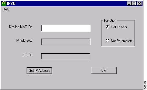
Step 2 When the utility window opens, make sure the Get IP addr radio button in the Function box is selected.
Step 3 Enter the access point/bridge's MAC address in the Device MAC ID field. The access point/bridge's MAC address is printed on the label on the bottom of the unit. It should contain six pairs of hexadecimal digits. Your access point/bridge's MAC address might look like the following example:
000164xxxxxx
Note The MAC address field is not case-sensitive.
Step 4 Click Get IP Address.
Step 5 When the access point/bridge's IP address appears in the IP Address field, write it down.
If IPSU reports that the IP address is 10.0.0.1, the default IP address, then the access point/bridge did not receive a DHCP-assigned IP address. To change the access point/bridge IP address from the default value using IPSU, refer to the "Using IPSU to Set the Access Point/Bridge's IP Address and SSID" section.
Using IPSU to Set the Access Point/Bridge's IP Address and SSID
If you want to change the default IP address (10.0.0.1) of the access point/bridge, you can use IPSU. You can also set the access point/bridge's SSID at the same time.
Note IPSU can change the access point/bridge's IP address and SSID only from their default settings. After the IP address and SSID have been changed, IPSU cannot change them again.
Note The computer you use to assign an IP address to the access point/bridge must have an IP address in the same subnet as the access point/bridge (10.0.0.x).
Follow these steps to assign an IP address and an SSID to the access point/bridge:
Step 1 Double-click the IPSU icon on your computer desktop to start the utility.
Step 2 Click the Set Parameters radio button in the Function box (see Figure 2-5).
Figure 2-5 IPSU Set Parameters Screen
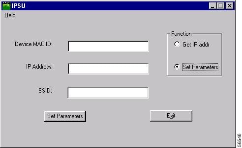
Step 3 Enter the access point/bridge's MAC address in the Device MAC ID field. The access point/bridge's MAC address is printed on a label on the access point/bridge. It should contain six pairs of hexadecimal digits. Your access point/bridge's MAC address might look like this example:
004096xxxxxx
Note The MAC address field is not case-sensitive.
Step 4 Enter the IP address you want to assign to the access point/bridge in the IP Address field.
Step 5 Enter the SSID you want to assign to the access point/bridge in the SSID field.
Note You cannot set the SSID without also setting the IP address. However, you can set the IP address without setting the SSID.
Step 6 Click Set Parameters to change the access point/bridge's IP address and SSID settings.
Step 7 Click Exit to exit IPSU.
Assigning an IP Address Using the CLI
When you connect the access point/bridge to the wired LAN, the access point/bridge links to the network using a bridge virtual interface (BVI) that it creates automatically. Instead of tracking separate IP addresses for the access point/bridge's Ethernet and radio ports, the network uses the BVI.
Note The access point/bridge supports only one BVI. Configuring more than one BVI might cause errors in the access point/bridge's ARP table.
When you assign an IP address to the access point/bridge using the CLI, you must assign the address to the BVI. Beginning in privileged EXEC mode, follow these steps to assign an IP address to the access point/bridge's BVI:
Using a Telnet Session to Access the CLI
Follow these steps to browse to access the CLI using a Telnet session. These steps are for a PC running Microsoft Windows with a Telnet terminal application. Check your PC operating instructions for detailed instructions for your operating system.
Step 1 Select Start > Programs > Accessories > Telnet.
If Telnet is not listed in your Accessories menu, select Start > Run, type Telnet in the entry field, and press Enter.
Step 2 When the Telnet window appears, click Connect and select Remote System.
Note In Windows 2000, the Telnet window does not contain drop-down menus. To start the Telnet session in Windows 2000, type open followed by the access point/bridge's IP address.
Step 3 In the Host Name field, type the access point/bridge's IP address and click Connect.
Using the Console Port to Access the CLI
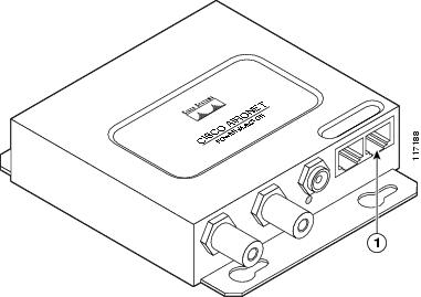
If you need to configure the access point/bridge locally (without connecting to a wired LAN), you can connect a PC to power injector's serial port using a DB-9 to RJ-45 serial cable. Follow these steps to access the CLI by connecting to the serial port:
Step 1 Connect a nine-pin, female DB-9 to RJ-45 serial cable to the RJ-45 serial port on the power injector and to the COM port on your PC. Figure 2-6 shows the power injector's serial port connector.
Figure 2-6 Serial Port Connector
Note The Cisco part number for the DB-9 to RJ-45 serial cable is AIR-CONCAB1200. Browse to http://www.cisco.com/go/marketplace to order a serial cable.
Step 2 Set up a terminal emulator to communicate with the access point/bridge. Use the following settings for the terminal emulator connection: 9600 baud, 8 data bits, no parity, 1 stop bit, and no flow control.
Step 3 When the terminal emulator is activated, press Enter. An Enter Network Password window appears.
Step 4 Enter your username in the User Name field. The default username is Cisco.
Step 5 Enter the access point/bridge password in the Password field and press Enter. The default password is Cisco.
When the CLI activates, you can enter CLI commands to configure the access point/bridge.