- Cisco Unity Express Features
- Overview of Cisco Unity Express Voice Mail and Auto Attendant
- Entering and Exiting the Command Environment
- Configuration Tasks
- Configuring System Components
- Configuring Users and Groups
- Configuring Voice Mail
- Configure Smart Licensing
- Configuring Authentication, Authorization, and Accounting
- Configuring the Administration via Telephone Application
- Configuring Auto Attendants
- Configuring Message Notification
- Configuring VoiceView Express
- Networking Cisco Unity Express
- Configuring Distribution Lists
- Configuring Security
- Backing Up and Restoring Data
- Language Support
- Configuring Advanced Voice Mail
- Advanced Configuration
- Monitoring the System
- Configuring SNMP Monitoring
- Registering Cisco Unity Express Endpoints to Cisco Unified Messaging Gateway
- Configuring Your Cisco IOS Gateway for T.37 On-Ramp and Off-Ramp Fax Support
- Troubleshooting
Cisco Unity Express VoiceMail and Auto Attendant CLI Administrator Guide
Bias-Free Language
The documentation set for this product strives to use bias-free language. For the purposes of this documentation set, bias-free is defined as language that does not imply discrimination based on age, disability, gender, racial identity, ethnic identity, sexual orientation, socioeconomic status, and intersectionality. Exceptions may be present in the documentation due to language that is hardcoded in the user interfaces of the product software, language used based on RFP documentation, or language that is used by a referenced third-party product. Learn more about how Cisco is using Inclusive Language.
- Updated:
- January 10, 2011
Chapter: Configuring System Components
- Configuring SIP Call Control Parameters
- Configuring the SIP Proxy Server Location for Cisco Unity Express
- Configuring the Call Transfer Mode
- Configuring DTMF Options
- Configuring the MWI Notification Option
- Configuring the MWI On and Off Extensions (Not Available in Cisco SRST Mode)
- Configuring the Inclusion of Envelope Information in SIP MWI Notifications
- Configuring Centralized CiscoUnityExpress
- Configuring FAX Support for Centralized Cisco Unity Express
- Configuring NonSubscriber Distribution Lists for Centralized Cisco Unity Express
- Configuring Cisco Unified CME SIP Options for RFC Compliance
- Configuring the Local Historical Reporting Database
- Configuring the Database Purge Schedule
- Configuring the Database Capacity Threshold for a Purge
- Configuring the Database Threshold Capacity for Warning Notification
- Configuring the Purge Notification E-mail Addresses
- Manually Purging the Historical Reporting Database
- Exporting Historical Report Data to an External Server
- Assigning Historical Report Viewing Privileges to a Group
Configuring System Components
Command-line interface (CLI) commands are available to configure Cisco Unity Express system components. You enter some commands in EXEC mode and others in configuration mode.
This chapter describes how to configure the following basic Cisco Unity Express components:
- SIP parameters that Cisco Unity Express must communicate with Cisco Unified Communications Manager Express (Cisco Unified CME).
- JTAPI parameters that Cisco Unity Express must communicate with Cisco Unified Communications Manager.
- Other Cisco Unity Express system components such as Prompts, Scripts, Applications, Triggers, and so on.
All the procedures in this chapter can be implemented using either CLI commands or the graphical user interface (GUI) options. Use the CLI procedures for:
This chapter contains the following procedures for configuring Cisco Unity Express system components:
–![]() Configuring the SIP Proxy Server Location for Cisco Unity Express
Configuring the SIP Proxy Server Location for Cisco Unity Express
–![]() Configuring the Call Transfer Mode
Configuring the Call Transfer Mode
–![]() Configuring the MWI Notification Option
Configuring the MWI Notification Option
–![]() Configuring the MWI On and Off Extensions (Not Available in Cisco SRST Mode)
Configuring the MWI On and Off Extensions (Not Available in Cisco SRST Mode)
–![]() Configuring Centralized Cisco Unity Express
Configuring Centralized Cisco Unity Express
–![]() Configuring FAX Support for Centralized Cisco Unity Express
Configuring FAX Support for Centralized Cisco Unity Express
–![]() Configuring NonSubscriber Distribution Lists for Centralized Cisco Unity Express
Configuring NonSubscriber Distribution Lists for Centralized Cisco Unity Express
–![]() Configuring Cisco Unified CME SIP Options for RFC Compliance
Configuring Cisco Unified CME SIP Options for RFC Compliance
Configuring SIP Call Control Parameters
- Configuring the SIP Proxy Server Location for Cisco Unity Express
- Configuring the Call Transfer Mode
- Configuring DTMF Options
- Configuring the MWI Notification Option
- Configuring the MWI On and Off Extensions (Not Available in Cisco SRST Mode)
- Configuring Cisco Unified CME SIP Options for RFC Compliance
Configuring the SIP Proxy Server Location for Cisco Unity Express
The Session Initiation Protocol (SIP) proxy server resides on the router where Cisco Unified CME is installed. Cisco Unified CME can be installed on a different router from where the Cisco Unity Express hardware and software is installed. The SIP proxy server location information must be configured properly to enable all communications between Cisco Unity Express and Cisco Unified CME. The SIP proxy server also enables the message waiting indicators (MWIs) to work with the Cisco Unity Express voice-mail application.
Required Data for This Procedure
The following information is required to configure the SIP proxy server:
SUMMARY STEPS
DETAILED STEPS
Examples
The following example illustrates the show ccn subsystem sip output, which displays the SIP gateway IP address and SIP port number:
Configuring the Call Transfer Mode
Cisco Unity Express permits configuration of attended and semiattended call transfer modes in addition to blind transfers.
SUMMARY STEPS
3.![]() transfer-mode { attended | semi-attended | blind refer | blind bye-also ]}
transfer-mode { attended | semi-attended | blind refer | blind bye-also ]}
DETAILED STEPS
Examples
The following is example output of the show ccn subsystem sip command.
Configuring DTMF Options
The listed options are available for handling incoming and outgoing DTMF signals for SIP calls from Cisco Unified CME and Cisco SRST mode.
Cisco Unity Express provides the following options for transferring DTMF signals for incoming and outgoing SIP calls.
To use the rtp-nte option, verify that the Cisco IOS SIP gateway is configured to use RTP-NTE for SIP calls, as shown in the following example:
- sub-notify —Uses Subscribe and Notify messages to relay incoming DTMF signals to Cisco Unity Express. This option is not available for outgoing DTMF signals from Cisco Unity Express.
- info —Uses the Info message to relay outgoing DTMF signals from Cisco Unity Express to the Cisco IOS SIP gateway. This option is not available for incoming DTMF signals to Cisco Unity Express.
- sip-notify —Uses Unsolicited-Notify messages for incoming and outgoing DTMF signals.
To use the sip-notify option, verify that the Cisco IOS SIP gateway is configured to use Unsolicited NOTIFY for SIP calls, as shown in the following example:
You can configure more than one option for transferring DTMF signals. The order in which you configure the options determines their order of preference.
Table 5-1 shows the various option combinations, the remote end capability, and the signaling option for incoming and outgoing DTMF signals.
|
|
|
|
|
|---|---|---|---|
sip-notify1 |
|||
no support2 |
|||
|
1.For incoming call. For outgoing call, the remote end decides between rtp-nte and sip-notify. |
SUMMARY STEPS
3.![]() dtmf-relay { rtp-nte | sub-notify | info | sip-notify }
dtmf-relay { rtp-nte | sub-notify | info | sip-notify }
To configure more than one signal option, specify them using a single dtmf-relay command.
DETAILED STEPS
Examples
The following example displays the output of the show ccn subsystem sip command.
Configuring the MWI Notification Option
Cisco Unity Express expands MWI status update capability to include Cisco Unified Communications Manager and Cisco SRST mode. Three notification options are available:
- Outcall Notification (Not Available in Cisco SRST Mode)
- Sub-Notify Notification
- Unsolicited Notification
From the GUI, select Voice Mail > Message Waiting Indicators > Settings to configure the MWI notification option.
Outcall Notification (Not Available in Cisco SRST Mode)
Only Cisco Unified CME can use the SIP outcall mechanism for generating MWI notifications. Outcall will not work in Cisco SRST mode.

Note![]() If the MWI notification option is outcall, configure the MWI on and off extensions. See Configuring the MWI On and Off Extensions (Not Available in Cisco SRST Mode).
If the MWI notification option is outcall, configure the MWI on and off extensions. See Configuring the MWI On and Off Extensions (Not Available in Cisco SRST Mode).
The outcall option is available for backward compatibility. We recommend that you use either sub-notify or unsolicited for the MWI notification option.
To use the outcall option, Cisco Unified CME must configure two ephone-dns that are registered to receive MWI notifications as follows:
Note![]() The number of dots in the above example must be equal to the extension length of the phones connected to Cisco Unified CME.
The number of dots in the above example must be equal to the extension length of the phones connected to Cisco Unified CME.
Sub-Notify Notification
Both Cisco Unified CME and Cisco Unified Communications Manager in SRST mode can use the sub-notify mechanism for generating MWI notifications. With this mechanism, the MWI notifications will reflect the accurate status of messages in a subscriber’s voice mailbox.
After an ephone-dn is configured with the sub-notify option, Cisco Unified CME sends a Subscribe message to Cisco Unity Express to register the phone for MWI notifications. When a new voice message arrives in the voice mailbox for the ephone-dn, Cisco Unity Express updates the MWI status. If Cisco Unity Express does not receive the Subscribe message for the ephone-dn, Cisco Unity Express will not update the MWI status when a new message arrives.
To use the sub-notify option, Cisco Unified CME must configure each ephone-dn that is registered to receive MWI notifications as follows:
For Cisco IOS Releases Prior to 12.3(11)T7
For Cisco IOS Releases 12.3(11)T7 and Later Releases
Note![]() The SIP server IP address used in these commands must be the IP address of Cisco Unity Express. In the examples shown above, this is 10.100.9.6.
The SIP server IP address used in these commands must be the IP address of Cisco Unity Express. In the examples shown above, this is 10.100.9.6.
Unsolicited Notification
Both Cisco Unified CME and Cisco Unified Communications Manager in SRST mode can use the unsolicited mechanism for generating MWI notifications. With this mechanism, the MWI notifications will reflect the accurate status of messages in a subscriber’s voice mailbox.
The unsolicited option does not require Cisco Unified CME to send a subscription request for each ephone-dn to Cisco Unity Express for MWI notifications. Cisco Unity Express sends Notify messages to Cisco Unified CME whenever the voice mailbox for any ephone-dn receives a new message. In this way, the MWI status reflects the current voice mailbox message status.
To use the unsolicited option, Cisco Unified CME must configure each ephone-dn that is registered to receive MWI notifications as follows:
For Cisco IOS Releases Prior to 12.3(11)T7
For Cisco IOS Release 12.3(11)T7 and Later Releases
Note![]() The SIP server IP address used in these commands must be the IP address of Cisco Unity Express. In the examples shown above, this is 10.100.9.6.
The SIP server IP address used in these commands must be the IP address of Cisco Unity Express. In the examples shown above, this is 10.100.9.6.
SUMMARY STEPS
DETAILED STEPS
|
|
|
|
|---|---|---|
|
|
||
|
|
||
mwi sip { outcall | sub-notify | unsolicited } |
Specifies the MWI notification methods for SIP calls. The default is outcall. |
|
|
|
||
|
|
Examples
The following example displays the output of the show ccn subsystem sip command.
Configuring the MWI On and Off Extensions (Not Available in Cisco SRST Mode)
Cisco Unity Express uses the MWI on and off extensions with the affected telephone extension to generate a SIP call to Cisco Unified CME, which changes the status of the telephone’s MWI light.
This configuration is required only if the MWI notification option is configured as outcall. (See the earlier section Configuring the MWI Notification Option.)
Prerequisites
Verify that the MWI on and off extensions are configured on Cisco Unified CME; otherwise, the MWI light will not work.
Required Data for This Procedure
The following information is required to configure the MWI on and off extensions:
SUMMARY STEPS
2.![]() ccn application ciscomwiapplication
ccn application ciscomwiapplication
3.![]() parameter strMWI_ON_DN on-extension
parameter strMWI_ON_DN on-extension
DETAILED STEPS
Configuring the Inclusion of Envelope Information in SIP MWI Notifications
To determine whether envelope information is included in SIP MWI notifications, use the mwi envelope-info command.
Enabling the inclusion of envelope information in SIP MWI notifications does not effect whether Cisco Unity Express accepts MWI subscriptions that request envelope information. It only determines whether envelope information is not included in SIP MWI notifications and it effects only the content of MWI messages generated by Cisco Unity Express. Disabling the inclusion of envelope information does not terminate existing MWI subscriptions. After it is enabled, subsequent MWI notifications include envelope information for any existing MWI subscription that requested with envelope information
Prerequisites
- Cisco Unity Express 3.2 or a later version
- The mwi envelope-info command is relevant only when the mwi sip sub-notify command is used. For more information about the mwi sip sub-notify command, see the earlier section Configuring the MWI Notification Option.)
SUMMARY STEPS
DETAILED STEPS
|
|
|
|
|---|---|---|
|
|
||
|
|
||
|
|
Enables the inclusion of envelope information in SIP MWI notifications. |
|
|
|
||
copy running-config startup-config |
Copies the configuration changes to the startup configuration. |
Configuring Centralized Cisco Unity Express
Available in Cisco Unity Express 3.2 and later versions, the centralization feature enables the Cisco Unity Express NME or Cisco Unity Express SM-SRE-700-K9 to interoperate with up to ten Cisco Unified CME systems.
Note![]() The Cisco Unity Express AIM-CUE/AIM2-CUE, NM-CUE, NM-CUE-EC and ISM-SRE-300-K9 modules support only one Cisco Unified CME system.
The Cisco Unity Express AIM-CUE/AIM2-CUE, NM-CUE, NM-CUE-EC and ISM-SRE-300-K9 modules support only one Cisco Unified CME system.
Geographically dispersed Cisco Unified CME systems can be connected to Cisco Unity Express across a WAN link. Cisco Unity Express can be co-located with one of these Cisco Unified CME systems, although it is not required.
Figure 5-1 Centralized Cisco Unity Express Deployment Topology
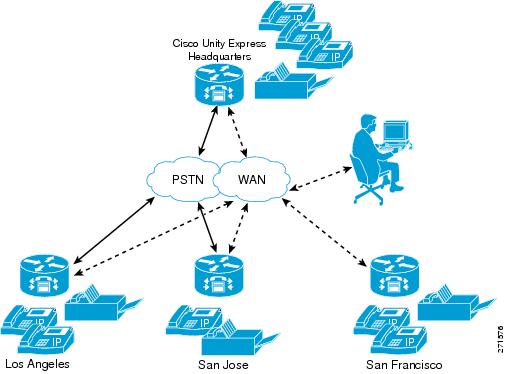
To interconnect more than ten Cisco Unified CME systems, you can use Cisco Unified Messaging Gateway to interconnect multiple Cisco Unity, Cisco Unity Express, and third party messaging systems.
Note![]() Cisco Unity Express does not support importing and/or managing Cisco Unified CME Extension Mobility (EM) users, only ephone users.
Cisco Unity Express does not support importing and/or managing Cisco Unified CME Extension Mobility (EM) users, only ephone users.
To receive the greatest benefit from the centralization feature, you must configure a single central Cisco Unified CME gateway to manage the company’s dial-plan. This central Cisco Unified CME gateway is called the “local” site and is a predefined site on the system. The local site cannot be deleted.
Cisco Unity Express uses one SIP gateway for all outgoing calls and faxes. This SIP gateway must be aware of the company’s dial-plan and be capable of routing calls from Cisco Unity Express to any Cisco Unified CME in the network. This gateway is configured independently of the sites, but by default, it routes to the Cisco Unified CME at the local site.
If you plan to use Outcall or Unsolicited Notify for MWI, the MWI relay must be enabled on the central (local) Cisco Unified CME and the other Cisco Unified CME routers must subscribe to this one. The central one will keep track of which numbers are defined where and pass on the MWI messages accordingly.
If you plan to use Subscribe-Notify for MWI, then the individual gateways must use Cisco Unity Express as their MWI server.
Note![]() Cisco Unity Express does not support automatic MWI synchronization if the WAN link between Cisco Unity Express and Cisco Unified CME is disrupted. You must manually synchronize the MWI if it is out of synch.
Cisco Unity Express does not support automatic MWI synchronization if the WAN link between Cisco Unity Express and Cisco Unified CME is disrupted. You must manually synchronize the MWI if it is out of synch.
The detailed MWI relay design guide, the MWI Relay section of the Cisco Unified Communications Manager Express Solution Reference Network Design Guide, is located at http://www.cisco.com/en/US/docs/voice_ip_comm/cucme/srnd/design/guide/cmesrnd.html .
The commands listed in the following are not available when Cisco Unity Express is working in Cisco Unified Communications Manager mode.
The following instructions describe how t o provision Cisco Unified CME sites:
–![]() Defining a Cisco Unified CME Site (Site Provisioning)
Defining a Cisco Unified CME Site (Site Provisioning)
–![]() Deleting a Cisco Unified CME Site
Deleting a Cisco Unified CME Site
Note![]() The following procedures replace the following EXEC mode command found in Cisco Unity Express 3.1 and earlier versions, whose purpose was to provision the single Cisco Unified CME it supported:
The following procedures replace the following EXEC mode command found in Cisco Unity Express 3.1 and earlier versions, whose purpose was to provision the single Cisco Unified CME it supported:
web admin cme hostname [hostname] username [username] password [password].
Although this command has not been deprecated, when you have multiple Cisco Unified CME systems, this command will apply only to the central (local) site.
Defining a Cisco Unified CME Site (Site Provisioning)
Prerequisites
SUMMARY STEPS
2.![]() site name [ site-name | local ]
site name [ site-name | local ]
5.![]() web username username password password
web username username password password
6.![]() web credentials hidden username-password-hash
web credentials hidden username-password-hash
7.![]() xml username username password password
xml username username password password
8.![]() xml credentials hidden username-password-hash
xml credentials hidden username-password-hash
DETAILED STEPS
Deleting a Cisco Unified CME Site
The following configuration mode command deletes a site. You cannot delete the local site.
The syntax for the site name is the same as the username, containing letters, numbers, hyphens, and/or dots, maximum 32 characters.
Example
The following example illustrates some of the configurations described above.
Configuring FAX Support for Centralized Cisco Unity Express
Prerequisites
SUMMARY STEPS
2.![]() fax gateway inbound address {ip-address | hostname}
fax gateway inbound address {ip-address | hostname}
DETAILED STEPS
Examples
The following example configures the inbound fax gateway IP address:
The following example sets the site’s fax number to 555-0112:
The following is sample output for the show fax configuration command if only one site is configured:
The following is sample output for the show fax configuration command if more than one site is configured:
Configuring NonSubscriber Distribution Lists for Centralized Cisco Unity Express
To configure NonSubscriber Distribution Lists for Centralized Cisco Unity Express, see Configuring Public Distribution Lists.
Configuring Cisco Unified CME SIP Options for RFC Compliance
Cisco Unity Express provides the protocol command to ensure compatibility with all Cisco IOS releases. Cisco IOS Release 12.4(2)T and earlier releases are not RFC 3261 compliant. The lack of compliance causes the Cisco Unity Express software not to interoperate properly with those older Cisco IOS releases when sip-notify or sub-notify are used for DTMF.
Required Data for This Procedure
The release number of the Cisco IOS software running on your call control platform.
SUMMARY STEPS
DETAILED STEPS
|
|
|
|
|---|---|---|
|
|
||
|
|
||
protocol { pre-rfc3261 | rfc3261 } |
||
|
|
||
|
|
Example
The following example sets the SIP option to RFC 3261 for call platforms using Cisco IOS Release 12.4(2)T or a later release.
Following is example output of the show ccn subsystem sip command.
Configuring JTAPI Parameters (Cisco Unified Communications Manager Only)
Use this procedure to configure the parameters that Cisco Unity Express must communicate with Cisco Unified Communications Manager. These parameters include:
- Up to three Cisco Unified Communications Manager servers
- JTAPI user ID and password
- JTAPI CTI ports that are configured on Cisco Unified Communications Manager and that are associated with the Cisco Unified Communications Manager JTAPI user
- Optional separate CTI port to use for MWI
Note![]() To configure CTI ports for MWI, the Cisco Unified Communications Manager must have a CTI port that is assigned the DN you specify when you configure the CTI port, and the DN must be under the control of Cisco Unity Express JTAPI application user.
To configure CTI ports for MWI, the Cisco Unified Communications Manager must have a CTI port that is assigned the DN you specify when you configure the CTI port, and the DN must be under the control of Cisco Unity Express JTAPI application user.
If an MWI port is configured on Cisco Unity Express but the DN is not in service, or Cisco Unity Express cannot register the port, no notifications are generated. If no MWI port is configured, Cisco Unity Express uses one of the CTI ports configured with the ctiports command.
Cisco Unified Communications Manager and Cisco Unity Express Version Compatibility
Depending on the version, Cisco Unity Express can be configured to work with different versions of Cisco Unified Communications Manager. For more information see the Cisco Unity Express Compatibility Matrix.
The following scenarios apply when installing Cisco Unity Express with a different version of Cisco Unified Communications Manager, or upgrading the Cisco Unified Communications Manager version:
- By default, each version of Cisco Unity Express is set up to work with a specific version of Cisco Unified Communications Manager. Once you configure the IP Address or Hostname of the Cisco Unified Communications Manager, you must reload the Cisco Unity Express module for the configuration to take effect. After this reload, Cisco Unity Express automatically reloads again if the configured Cisco Unified Communications Manager version is different from the supported default version.
- If the Cisco Unified Communications Manager server being used by Cisco Unity Express is upgraded, Cisco Unity Express reloads and updates its system files to work with the new version of Cisco Unified Communications Manager. No further action from you is required.
Prerequisites
To use a separate CTI port for MWI, you must have 3.2 or later releases.
Required Data for This Procedure
The following information is required to configure the JTAPI parameters:
- IP address or hostname for the primary, secondary, and tertiary Cisco Unified Communications Manager servers
- JTAPI user ID and password from Cisco Unified Communications Manager. The password is case sensitive. These values must match the JTAPI user ID and password that were configured on Cisco Unified Communications Manager.
- List of CTI ports
- To use a separate CTI port for MWI, a list of DNs that are assigned on Cisco Unified Communications Manager and are under the control of Cisco Unity Express JTAPI application user.
Note![]() If you are using Cisco Unified Communications Manager 5.0 or a later version, verify that the AXL service is active. To do this, go to the Cisco Unified Communications Manager serviceability website, click on Tools > Service Activation. Look for Cisco AXL Web service.
If you are using Cisco Unified Communications Manager 5.0 or a later version, verify that the AXL service is active. To do this, go to the Cisco Unified Communications Manager serviceability website, click on Tools > Service Activation. Look for Cisco AXL Web service.
SUMMARY STEPS
3.![]() ccm-manager address {primary-server-ip-address | primary-server-hostname} { secondary-server-ip-address | secondary-server-hostname }
ccm-manager address {primary-server-ip-address | primary-server-hostname} { secondary-server-ip-address | secondary-server-hostname }
{ tertiary-server-ip-address | tertiary-server-hostname }
4.![]() ccm-manager username jtapi-user-id password jtapi-user-password
ccm-manager username jtapi-user-id password jtapi-user-password
7.![]() redirect-css cti-port { ccm-default | calling-party | redirecting-party }
redirect-css cti-port { ccm-default | calling-party | redirecting-party }
8.![]() redirect-css route-point { ccm-default | calling-party | redirecting-party }
redirect-css route-point { ccm-default | calling-party | redirecting-party }
DETAILED STEPS
|
|
|
|
|---|---|---|
|
|
||
|
|
||
ccm-manager address {primary-server-ip-address | primary-server-hostname} { secondary-server-ip-address | secondary-server-hostname } { tertiary-server-ip-address | tertiary-server-hostname } se-10-0-0-0(config-jtapi)# ccm-manager address 10.100.10.120 se-10-0-0-0(config-jtapi)# ccm-manager address 10.100.10.120 10.120.10.120 10.130.10.120 |
Specifies up to three Cisco Unified Communications Manager servers. Enter the server IP addresses or hostnames on one command line or on separate command lines. If entered on separate lines, the servers are assigned in order as primary, secondary, and tertiary servers. |
|
ccm-manager username jtapi-user-id password jtapi-user-password |
Specifies the JTAPI user ID and password. The password is case sensitive. These values must match the JTAPI user ID and password that were configured on Cisco Unified Communications Manager. |
|
ctiport cti-port1 cti-port2 cti-port3 cti-port4... se-10-0-0-0(config-jtapi)# ctiport 7008 se-10-0-0-0(config-jtapi)# ctiport 7009 se-10-0-0-0(config-jtapi)# ctiport 7010 se-10-0-0-0(config-jtapi)# ctiport 7011 se-10-0-0-0(config-jtapi)# ctiport 6001 6002 6003 6004 6005 6006 6007 6008 |
Specifies the JTAPI CTI ports that are configured on Cisco Unified Communications Manager and that are associated with the Cisco Unified Communications Manager JTAPI user. Repeat this command to enter more than one port number or enter the ports on one line. You can specify up to the maximum number of ports supported for each module type. For information on the number of ports supported, see the Release Notes for Cisco Unity Express. |
|
|
|
(Optional) Configures a separate CTI port to use for MWI. The DN must be different from those used by any of the CTI ports (as configured using the ctiport command). |
|
redirect-css cti-port {ccm-default | calling-party | redirecting-party} se-10-0-0-0(config-jtapi)# redirect-css cti-port redirecting-party |
(Optional) Specifies the calling search space used to redirect calls from CTI ports to elsewhere. |
|
redirect-css route-point {ccm-default | calling-party | redirecting-party} se-10-0-0-0(config-jtapi)# redirect-css cti-port calling-party |
(Optional) Specifies the calling search space used to redirect calls from route points to CTI ports. |
|
|
|
||
|
|
||
copy running-config startup-config |
Copies the configuration changes to the startup configuration. |
Examples
Following is example output of the show ccn subsystem jtapi command:
se-10-0-0-0# show ccn subsystem jtapi
Managing Scripts
Cisco Unity Express provides you with building blocks (known as Steps) through its Cisco Unity Express Editor Software, which can be used to create customized call-flows for various applications such as auto-attendant or IVR applications. These call flows can be saved as AEF files (known as scripts).
Cisco Unity Express ships with some internal scripts, which are known as system scripts. These system scripts cannot be downloaded, modified or deleted. The number of custom scripts supported depends on the hardware module and the release. For more information, see the the Release Notes for Cisco Unity Express.
Customizing scripts involves the following procedures:
- Creating a Script File
- Uploading a Script File
- Displaying the List of Existing Scripts
- (Optional) Downloading a Script File
- (Optional) Deleting a Script File
Creating a Script File
To create a script file, use the Cisco Unity Express Editor software. See to the Cisco Unity Express Guide to Writing Auto-Attendant Scripts for guidelines and procedures for creating a script file.
The file cannot be larger than 256 KB. Starting with Cisco Unity Express 3.1, script files can also be created using Editor Express. Editor Express can be accessed using the GUI option System > Scripts > New.
Note![]() Cisco Unity Express Editor Express provides only a subset of the functionality that is available the Cisco Unity Express Script Editor. Use Cisco Unity Express Editor Express for simple call-flow customizations only.
Cisco Unity Express Editor Express provides only a subset of the functionality that is available the Cisco Unity Express Script Editor. Use Cisco Unity Express Editor Express for simple call-flow customizations only.
After creating the script, use the GUI or Cisco Unity Express ccn copy command to upload the file to the Cisco Unity Express module. See the next section, “Uploading a Script File,” for the upload procedure.
Note![]() If you create your script using Cisco Unity Express Editor Express, you do not need to upload because it is directly saved on the Cisco Unity Express module.
If you create your script using Cisco Unity Express Editor Express, you do not need to upload because it is directly saved on the Cisco Unity Express module.
Uploading a Script File
After creating the AEF file, upload the file using the ccn copy url command in Cisco Unity Express EXEC mode:
ccn copy url ftp:// source-ip-addres s/script-filename.aef script script-filename.aef [username username password password]
This command is equivalent to using the GUI option Voice Mail > Scripts and selecting Upload.
An error message appears if you try to upload more than the maximum number of scripts allowed on your Cisco Unity Express module.
Displaying the List of Existing Scripts
To displays details of the script files existing on the module, use the following command in Cisco Unity Express EXEC mode:
Downloading a Script File
Scripts can be copied from the auto-attendant and stored on another server or PC.
To download or copy a script file, use the ccn copy script command in Cisco Unity Express EXEC mode:
ccn copy script script-filename url ftp:// destination-ip-addres s / script-filename
Deleting a Script File
To delete an auto-attendant script file from Cisco Unity Express, use the ccn delete command in Cisco Unity Express EXEC mode:
ccn delete script script-filename
Managing Prompts
Cisco Unity Express supports customized prompt files. See the Release Notes for Cisco Unity Express for your release for the number of customized prompts supported on your hardware module.
Customizing prompts requires the following procedures:
- Recording a Prompt File (required)
- Uploading a Prompt File (required)
- Downloading a Prompt File (optional)
- Renaming a Prompt File(optional)
- Deleting a Prompt File (optional)
- Rerecording a Prompt File (optional)
Recording a Prompt File
Two methods are available to create prompt files:
- Create a wav file with the following format: G.711 u-law, 8 kHz, 8 bit, Mono. The file cannot be larger than 1 MB (about 2 minutes). After recording the wav file, use the GUI or Cisco Unity Express CLI ccn copy url command to copy or upload the file to the Cisco Unity Express module. See the next section, “Uploading a Prompt File,” for the upload procedure.
- Cisco Unity Express provides an in-built application called Administration via Telephone (AvT), which lets you record customized prompt files directly on the module using a telephone. For details on how to configure and use AvT, see the chapter Configuring the Administration via Telephone Application.
We recommend using the AvT on the TUI to record greetings and prompts because the AvT provides higher sound quality compared to.wav files recorded using other methods.
Uploading a Prompt File
After recording the.wav prompt file, upload the file using the ccn copy url command in Cisco Unity Express EXEC mode:
ccn copy url source-ip-addres s prompt prompt-filename [ language xx_YY ] [ username name password password ]
where prompt-filename is the file to be uploaded, xx_YY is the language of the prompt file, name is the FTP server login ID, and password is the FTP server password.
The optional language parameter lets you specify the language directory in which you want the prompt to be uploaded. An error message appears if the language specified in the command is not installed on the module. If the language parameter is omitted in this CLI command, the prompt is uploaded to the default system language directory.
This command is equivalent to using the GUI option Voice Mail > Prompts and selecting Upload.
An error message appears if you try to upload more than the maximum number of prompts allowed on your Cisco Unity Express module.
Displaying Existing Prompt File lists
To display details of the prompt files existing on the module, use the following command in Cisco Unity Express EXEC mode:
show ccn prompts [language xx_YY ]
The optional language parameter lets you specify the language directory from which the prompts will be listed. If the language parameter is omitted in this CLI command, then prompts from all language directories are listed.
Downloading a Prompt File
Prompts can be copied from the Cisco Unity Express module and stored on another server or PC.
To copy or download a prompt file, use the ccn copy prompt command in Cisco Unity Express EXEC mode:
ccn copy prompt prompt-filename url ftp: // destination-ip-addres s / prompt-filename [ language xx_YY ] [ username name password password ]
where prompt-filename is the file to be downloaded, destination-ip-address is the IP address of the FTP server, xx_YY is the language directory from which the prompt file is to be downloaded, name is the FTP server login ID, and password is the FTP server password.
Renaming a Prompt File
To rename a prompt file already existing on the Cisco Unity Express module, use the ccn rename prompt command in Cisco Unity Express EXEC mode:
ccn rename prompt old-name new-name [ language xx_YY ]
where old-name is the existing filename and new-name is the revised name, and xx_YY is the language directory in which the prompt to be renamed resides. If the language parameter is omitted in this CLI command, the system renames the prompt old-name from the default system language directory.
An error message appears if the prompt old-name does not exist in that language directory.
se-10-0-0-0# ccn rename prompt AAmyprompt.wav AAmyprompt2.wav
Deleting a Prompt File
To delete a prompt file from the Cisco Unity Express module, use the ccn delete command in Cisco Unity Express EXEC mode:
ccn delete prompt prompt-filename [ language xx_YY ]
where prompt-filename is the file to be deleted, and xx_YY is the language directory from which the prompt is to be deleted. If the language parameter is omitted from this CLI command, the system attempts to delete this prompt from the default system language directory.
An error message appears if the prompt prompt-filename does not exist in that language directory.
Rerecording a Prompt File
You can rerecord existing prompt files using the AvT application.
For details on how to rerecord prompts using AvT, see the “Configuring the Administration via Telephone Application” section.
Managing Applications
After you complete your pre-application tasks by uploading your scripts and prompts, you must create an application on the Cisco Unity Express module.
Cisco Unity Express supports two types of applications:
- Auto-Attendant Applications: This option is available with basic the Voice Mail license.
- Interactive Voice Response (IVR) Applications: IVR license must be purchased and installed in order to create IVR applications.
Cisco Unity Express ships with some internal applications, which are known as system applications. These system applications cannot be deleted.
The maximum number of custom Auto-Attendant applications that can be created on Cisco Unity Express is four, regardless of the hardware type. The maximum number of custom IVR applications that can be created differs depending on the hardware module. See the Release Notes for Cisco Unity Express for your release for the maximum number of custom IVR applications that can be created on your system.
This section describes the procedure for managing applications and contains the following sections:
- Creating and Modifying Applications (required)
- Script Parameters for Applications
- Deleting an Application
Creating and Modifying Applications
Use the following procedure to create or modify an application.
Required Data for This Procedure
- Application name.
- Script name for the application.
- Maxsessions value. See the “Sharing Ports Among Applications and Triggers” section.
- Name and value for each parameter that the script requires. These may vary, depending on the script that you have created.
Note![]() For more information about creating scripts, see the Cisco Unity Express Guide to Writing Scripts.
For more information about creating scripts, see the Cisco Unity Express Guide to Writing Scripts.
SUMMARY STEPS
2.![]() ccn application full-name [ aa | ivr ]
ccn application full-name [ aa | ivr ]
3.![]() default [description | enabled | maxsessions | script | parameter name]
default [description | enabled | maxsessions | script | parameter name]
6.![]() no [description | enabled | maxsessions | script | parameter name]
no [description | enabled | maxsessions | script | parameter name]
DETAILED STEPS
|
|
|
|
|---|---|---|
|
|
||
ccn application full-name [ aa | ivr ] |
Specifies the application to configure and enters application configuration mode. The full-name argument specifies the name of the application to configure. The optional parameter aa specifies that the application being configured is an Auto-Attendant application. The optional parameter ivr specifies that the application being configured is an IVR application. The default application type (when no optional parameter is specified) is Auto-Attendant. |
|
default [ description | enabled | maxsessions | script | parameter name ] |
||
|
se-10-0-0-0(config-application)# description “my application” |
(Optional) Enter a description of the application. Use quotes around the text. |
|
|
|
Specifies the number of callers who can access this application simultaneously. |
|
no [description | enabled | maxsessions | script | parameter name] |
||
|
se-10-0-0-0(config-application)# parameter MaxRetry “4” se-10-0-0-0(config-application)# parameter WelcomePrompt “Welcome.wav” |
Configures script parameters for the application. Each parameter must have a name and a value, which is written within quotes. For more details on Script Parameters, see the “Script Parameters for Applications” section. |
|
|
|
Specifies the name of the script that will be used by the application. |
|
|
|
||
|
|
||
show ccn application [ aa | ivr ] |
Displays details of the specified type of application. If no application type is specified, all applications on the system are displayed. |
|
copy running-config startup-config |
Copies the configuration changes to the startup configuration. |
Examples
The following example illustrates the show ccn application output:
Script Parameters for Applications
While creating a script with Cisco Unity Express Script Editor, you can specify some script variables to be “parameters.” The value of these “parameters” can be easily modified using the Cisco Unity Express configuration commands, without the need to edit the script using the Cisco Unity Express Script Editor. This has two benefits:
- You can deploy the same script at multiple locations and still customize the script flow to some extent for that particular location without needing different scripts for different locations. For example, you can create a simple script which welcomes the caller by playing a prompt such as “Welcome to ABC stores,” and then transfers the caller to the operator. You can specify this welcome prompt and the operator extension as script parameters while creating the script. Then you can deploy the same script at multiple locations and change the welcome prompt and operator extension by using the Cisco Unity Express configuration commands.
- You can create multiple applications using the same script, but with different values for the script parameters, thereby allowing you to provide a different experience to the caller depending on the application being invoked.
To view a list of script parameters, create an application using that script, and then use the show ccn application command to display the list of parameters and their default values.
To change the value of these parameters, see Step 7 in Creating and Modifying Applications.
Deleting an Application
If you have an application that you do not want to keep, use this procedure to delete the application and any triggers associated with that application.
After you delete the application and triggers, the script associated with the application still remains installed on the Cisco Unity Express module.
The following system applications ship with Cisco Unity Express, and cannot be deleted:
Required Data for This Procedure
The following information is required to delete an application:
SUMMARY STEPS
DETAILED STEPS
Examples
The following is sample output from the show ccn application and show ccn trigger commands:
The following configuration deletes the auto-attendant application and its trigger:
Now the output of the show commands looks similar to the following:
Managing Triggers
Triggers are incoming events that invoke application which in turn starts executing the script associated with that application. For example, the incoming event can be an incoming call or an incoming HTTP request.
After you have created and configured your application, you need to create a trigger on the Cisco Unity Express module to point to that application.
Cisco Unity Express supports three types of triggers:
- SIP triggers—Use this type of trigger to invoke applications in Cisco Unified CME and Cisco SRST mode. This type of trigger is identified by the phonenumber which is dialed to invoke the desired application.
- JTAPI triggers—Use this type of trigger to invoke applications in Cisco Unified Communications Manager mode. This type of trigger is identified by the phonenumber which is dialed to invoke the desired application.
- HTTP triggers—Use this type of trigger to invoke applications using an incoming HTTP request. Such a trigger is identified by the URL suffix of the incoming HTTP request. This type of trigger can only be used if an IVR license has been purchased and installed on the system.
Cisco Unity Express ships with some internal triggers, which are known as system triggers. These system triggers cannot be deleted.
This section describes the procedure for managing triggers and contains the following sections:
- Configuring SIP Triggers for the Applications
- Configuring JTAPI Triggers for the Applications (Cisco Unified Communications Manager Only)
- Configuring HTTP Triggers for the Applications
- Configuring Multiple Triggers for an Application
- Sharing Ports Among Applications and Triggers
Configuring SIP Triggers for the Applications
Cisco Unity Express uses SIP to handle incoming calls in Cisco Unified CME and Cisco SRST mode. If you are deploying Cisco Unity Express in either of these modes, you must configure a SIP trigger for your application so that it can be invoked by incoming calls. This type of trigger is identified by the phone number which is dialed to invoke the desired application.
The telephone number that identifies your SIP trigger must match the dial-peer configured on the Cisco IOS SIP gateway. In order for Cisco Unity Express to be able to handle incoming calls on this phone number properly, you must configure the dial-peer on the Cisco IOS SIP gateway as follows:
Note![]() Make sure that VAD is turned OFF on the dial-peer, it is configured to use g711ulaw codec and the session target is pointing to the Cisco Unity Express module.
Make sure that VAD is turned OFF on the dial-peer, it is configured to use g711ulaw codec and the session target is pointing to the Cisco Unity Express module.
Cisco Unity Express supports a maximum of 8 SIP triggers for all applications combined, regardless of the hardware type.
Required Data for This Procedure
The following information is required to configure the SIP triggers for applications:
- Telephone number that invokes the application. The number must be different for different applications. The number value must match one of the patterns configured in the destination-pattern field of the SIP dial peer pointing to Cisco Unity Express.
- Maximum number of callers that can access the trigger simultaneously. See Sharing Ports Among Applications and Triggers for guidelines on assigning this value.
SUMMARY STEPS
2.![]() ccn trigger sip phonenumber number
ccn trigger sip phonenumber number
DETAILED STEPS
|
|
|
|
|---|---|---|
|
|
||
ccn trigger sip phonenumber number se-10-0-0-0(config)# ccn trigger sip phonenumber 50150 |
Specifies the telephone number that acts as the trigger to start the application on the Cisco Unity Express module and enters trigger configuration mode.
Note |
|
|
se-10-0-0-0(config-trigger)# application voicemail se-10-0-0-0(config-trigger)# application autoattendant |
Specifies the name of the application to invoke when a call is made to the trigger phone number. |
|
|
|
||
|
|
Specifies the maximum number of callers that this application can handle simultaneously. See the “Sharing Ports Among Applications and Triggers” section for guidelines on assigning this value. |
|
|
|
(Optional) Specifies the trigger language. Any prompts being played out by an application invoked by this trigger will be played out in this language. Use this configuration only if you have more than one language installed on the system. The default for this configuration is to use the system default language as the trigger language. |
|
|
|
||
|
|
||
copy running-config startup-config |
Copies the configuration changes to the startup configuration. |
Examples
The following sample configuration sets two triggers on the Cisco Unity Express module:
se-10-0-0-0(config)# ccn trigger sip phonenumber 50150
se-10-0-0-0(config-trigger)# application voicemail
se-10-0-0-0(config-trigger)# maxsessions 4
se-10-0-0-0(config-trigger)# enabled
se-10-0-0-0(config)# ccn trigger sip phonenumber 50160
se-10-0-0-0(config-trigger)# application autoattendant
se-10-0-0-0(config-trigger)# maxsessions 3
se-10-0-0-0(config-trigger)# enabled
The output of show ccn trigger looks similar to the following:
Wild Card Trigger Patterns
Beginning with Cisco Unity Express 8.0, the trigger number can be a combination of digits and wildcard characters. Incoming calls targeted to a number that matches the pattern cause the associated script to be invoked. The script determines which number was dialed by inspecting the called number attribute associated with the call. Cisco Unity Express supports a limit of 32 characters in the trigger pattern. Wildcard patterns are supported for both SIP and JTAPI triggers.
Table 5-2 shows the trigger pattern wildcards and special characters supported in Cisco Unity Express 8.0.
Wildcard patterns are based on Cisco Unified Communications Manager route patterns. The rules for choosing between multiple wildcard patterns matching an incoming call are similar to those used by Cisco Unified Communications Manager. For each pattern that is a candidate match for the dial string, Cisco Unity Express calculates the number of other dial strings of the same length as the input dial string that would match each pattern, and then selects the pattern that has the fewest alternative dial string matches.
Configuring JTAPI Triggers for the Applications (Cisco Unified Communications Manager Only)
Cisco Unity Express uses JTAPI to handle incoming calls in Cisco Unified Communications Manager mode. If you are deploying Cisco Unity Express in Cisco Unified Communications Manager mode, you must configure a JTAPI trigger for your application so that it can be invoked by incoming calls. This type of trigger is identified by the phone number which is dialed to invoke the desired application.
The telephone number that identifies your JTAPI trigger must match the Route Point configured on the Cisco Unified Communications Manager.
Beginning in Cisco Unity Express 8.0, the trigger number can be a combination of digits and wildcard characters. See the “Wild Card Trigger Patterns” section.
Note![]() This Route Point must be associated with the JTAPI user configured on Cisco Unified Communications Manager. This same JTAPI user must also be configured on Cisco Unity Express module. See the “Configuring Triggers” section for details on JTAPI user configuration.
This Route Point must be associated with the JTAPI user configured on Cisco Unified Communications Manager. This same JTAPI user must also be configured on Cisco Unity Express module. See the “Configuring Triggers” section for details on JTAPI user configuration.
Cisco Unity Express supports a maximum of 8 JTAPI triggers for all applications combined, regardless of the hardware type.
This configuration is required for only for Cisco Unified Communications Manager mode.
Required Data for This Procedure
The following information is required to configure the JTAPI triggers for applications:
- Telephone number that invokes the application. The number must be unique for each application.
- Number of seconds the system must wait for a caller response before it times out and drops the call.
- Language to use for the prompts. Cisco Unity Express supports many languages. Only one can be installed on the system. See the Release Notes for Cisco Unity Express for a list of available languages.
- Maximum number of callers that can access the trigger simultaneously. See the “Sharing Ports Among Applications and Triggers” section for guidelines on assigning this value.
SUMMARY STEPS
2.![]() ccn trigger jtapi phonenumber number
ccn trigger jtapi phonenumber number
DETAILED STEPS
|
|
|
|
|---|---|---|
|
|
||
ccn trigger jtapi phonenumber number |
Specifies the telephone number that acts as the trigger to start the application on Cisco Unity Express and enters trigger configuration mode. The number value must match a JTAPI route point configured on Cisco Unified Communications Manager.
Note |
|
|
|
Specifies the name of the application to invoke when a call is made to the trigger phone number. |
|
|
|
||
|
|
Specifies the maximum number of callers that this trigger can handle simultaneously. See the “Sharing Ports Among Applications and Triggers” section for guidelines on assigning this value. |
|
|
|
(Optional) Specifies the trigger language. Any prompts being played out by an application invoked by this trigger will be played out in this language. Use this configuration only if you have more than one language installed on the system. The default for this configuration is to use the system default language as the trigger language. |
|
|
|
||
|
|
||
copy running-config startup-config |
Copies the configuration changes to the startup configuration. |
Examples
The following sample configuration sets two triggers on the Cisco Unity Express module:
se-10-0-0-0(config)# ccn trigger jtapi phonenumber 6500
se-10-0-0-0(config-trigger)# application voicemail
se-10-0-0-0(config-trigger)# maxsessions 4
se-10-0-0-0(config-trigger)# enabled
se-10-0-0-0(config)# ccn trigger jtapi phonenumber 6700
se-10-0-0-0(config-trigger)# application autoattendant
se-10-0-0-0(config-trigger)# maxsessions 8
se-10-0-0-0(config-trigger)# enabled
Output of the show ccn trigger command looks similar to the following:
Configuring HTTP Triggers for the Applications
Cisco Unity Express can accept incoming HTTP requests to invoke an application using an HTTP trigger. For example, you can use it to initiate an IVR application notifying customers that their order has been filled and shipped. This type of trigger is identified by the URL suffix of the incoming HTTP request.
This type of trigger can only be used if an IVR license has been purchased and installed on the system.
For details on how to configure and use HTTP triggers, see the Cisco Unity Express Interactive Voice Response CLI Administrator Guide.
Configuring Multiple Triggers for an Application
Your network may require multiple triggers for one or more Cisco Unity Express applications. For example, the following are some scenarios where multiple triggers for the same application are useful:
- Multiple language support—You have an auto-attendant application which you want to deploy in two different languages. One way to achieve this would be to have two different triggers (call-in numbers) pointing to the same application, but with different values for the locale parameter.
For example, assume that you have call-in numbers 6700 and 6900 (both pointing to the same auto-attendant application), the locale for the trigger 6700 is configured to be xx_XX, and the locale for the trigger 6900 is configured to be yy_YY. If the callers dial 6700, they will hear the auto-attendant greetings in the language xx_XX. If the callers dial 6900, they will hear the auto-attendant greetings in the language yy_YY. - Different call treatment for internal and external callers—You have an auto-attendant application, and you want to provide slightly different Menu options for internal and external callers. In other words, you want to provide an option to the internal callers to transfer to the inventory department, but you do not want to present this option to the external callers. One way to achieve this would be to have two different triggers (call-in numbers) pointing to the same application, and by making a branching decision in your script by checking the called number using the “Get Call Contact Info” step.
Repeat the procedure described in the “Configuring SIP Triggers for the Applications” section and the “Configuring JTAPI Triggers for the Applications (Cisco Unified Communications Manager Only)” section (depending on your deployment mode) to create multiple triggers for an application.
Sharing Ports Among Applications and Triggers
Accessing an Application
The maximum number of callers that can access an application concurrently is determined by two parameters:
- The maxsessions value configured for the triggers invoking the application.
- The maxsessions value configured for the application itself.
If more calls than the trigger's configured maxsession value are received, callers hear a busy tone.
If more calls than the application's configured maxsession value are received, Cisco Unity Express plays an error prompt to the callers.
The following example shows how the maxsessions values for applications and triggers play a role in how many active calls can be made to an application. In this example:
- Your module has 8 ports.
- You assigned the auto-attendant application a maxsessions value of 5.
- You configured 2 triggers both invoking the same auto-attendant application.
- You configured one trigger with a maxsessions value of 2 and the other trigger with a maxsessions value of 4.
The maximum number of callers that can access the auto-attendant application simultaneously is five, not six. This is because although your system has a total of six sessions available for the two triggers, they both are accessing the same application, which allows only five concurrent sessions. The maxsessions value of the application acts as the gating factor in this case.
If you configure both triggers with a maxsessions value of 2, the maximum number of concurrent calls to the application is four, not five. This is because the system has a total of only four ports assigned to the two triggers. The maxsessions value assigned to the triggers acts as the factor in this example.
Sharing Ports Among Different Applications
Cisco Unity Express supports multiple voice applications, and each of these applications need voice ports in order to execute. Consider the expected call traffic for each application when assigning the maxsessions for them. One application may have a higher call volume and therefore need more sessions than another, and at the same time you may want each application to have at least one session available for incoming calls. You should distribute the ports to your applications keeping in mind the usage of each application.
For example, your module has four ports and you configure the voice-mail application to have four maxsessions, and the auto-attendant application also to have four maxsessions. If four callers access voice-mail simultaneously, no ports is available for auto-attendant callers. Only when zero, one, two, or three callers access voice-mail simultaneously is at least one port available for auto-attendant.
As another example, you configure the voice-mail auto-attendant applications to have three maxsessions. At no time will one application use up all the ports. If voice-mail has three active calls, one caller can access auto-attendant. A second call to either voice-mail or auto-attendant is not successful.
Configuring Holiday Lists
Cisco Unity Express permits configuration of holiday lists that can be used by an application to play a customizable greeting to callers when the company is closed for a holiday. The following sections describe how to configure and use Cisco Unity Express holiday lists:
- Overview of Holidays
- Using the Holiday Lists
- Configuring Year-Specific Holiday Lists
- Displaying the Holiday List
- Deleting Holidays from the List
Overview of Holidays
Year-Specific Holidays
- Cisco Unity Express supports up to three year-specific holiday lists for: the previous year, the current year, and the next year. If a year has no configured entries, the system handles that year as having no year-specific holidays.
For example, if the current year is 2005 and you have not configured entries for 2006 (the next year), the system handles 2006 as having zero (0) holidays. You may configure holidays for 2005 and 2006 (the next year) but not for 2007.
- Each year-specific list can contain a maximum of 26 holidays.
- By default, all three year-specific holiday lists are empty.
- The administrator can delete entries from a previous year list but cannot add or modify that list in any other way.
- The system automatically deletes the previous year list at the beginning of the new calendar year.
- For example, the system will delete the 2004 holiday list on January 1, 2006.
- To copy holidays from one year to the next, use the GUI option Copy all to next year under System > Holiday Settings.
Fixed Holidays
- Fixed holidays are permanent holidays which apply to all years and do not need to be re-configured year after year (unlike year-specific holidays). If a holiday falls on the same date every year, those may be configured as fixed holidays.
For example, if your business is always closed on January 1st for New Year celebrations, then you may configure January 1st as a fixed holiday.
- A maximum of 10 fixed holidays can be configured on the system.
- By default, there are no fixed holidays configured on the system.
- Fixed holidays may overlap with year-specific holidays. If you create a year-specific holiday
- that overlaps with a fixed holiday, a warning is issued. However, no warning is issued if you try to create a fixed holiday that overlaps with a year-specific holiday.
To configure holiday lists, use the graphical user interface (GUI) System > Holiday Settings option or the command-line interface (CLI) commands described in this section.
Using the Holiday Lists
The Cisco Unity Express Editor provides a step “Is Holiday” that checks the holidays configured on the system to determine whether the specified date is a holiday or not. The step takes as input the date to check against the holiday list. See the Cisco Unity Express Guide to Writing and Editing Scripts for more information on steps.
For example, you can use the “Is Holiday” step in your script to check if the current day is a holiday. If it is a holiday, you can play a customized greeting to the caller, such as “We are closed today. If this is an emergency, please call 1-222-555-0150 for assistance. Otherwise, please call back later.”
Configuring Holiday Lists
Prerequisites
Configuring Year-Specific Holiday Lists
Use the following command in Cisco Unity Express configuration mode to configure a year-specific holiday list:
calendar holiday date yyyy mm dd [ description holiday-description ]
where yyyy is the 4-digit year, mm is the 2-digit month, dd is the 2-digit day, and holiday-description is an optional description of the holiday. If the description is more than one word, enclose the text in quotes (“ ”).
The valid values for yyyy are the current year or the next year. An error message appears if the year or date is out of range.
se-10-0-0-0(config)# calendar holiday date 2005 05 30 description “Memorial Day”
Configuring the Fixed Holiday List
Use the following command in Cisco Unity Express configuration mode to configure a fixed holiday:
calendar holiday fixed month day [description holiday- description ]
where month is the 2-digit month, day is the 2-digit day, and holiday-description is an optional description of the holiday. If the description is more than one word, enclose the text in quotes (“ ”).
se-10-0-0-0(config)# calendar holiday fixed 07 04 description “Independence Day”
Displaying the Holiday List
Several CLI commands are available in Cisco Unity Express EXEC mode for displaying the holiday lists.
Prerequisites
Displaying All Holiday Lists
The following command displays all the holiday lists configured on the system:
This command displays the date and description for all holidays for all years. This display includes both year-specific holidays and fixed holidays. The output of this command appears similar to the following:
Displaying Holiday Lists for a Specific Year
The following command displays the holidays configured for a specific year:
show calendar holiday year yyyy
where yyyy is the 4-digit year. This command displays the date and description for all holidays configured for the specified year. This display includes both year-specific holidays and fixed holidays. If no holidays are configured for that year and the fixed holiday list is empty, the message “No holidays found for the specified year” appears. The output of this command appears similar to the following:
Displaying Holiday Lists for a Specific Month
The following command displays the holidays configured for a specific month in a specified year:
show calendar holiday year yyyy month mm
where yyyy is the 4-digit year and mm is the 2-digit month. This command displays the date and description for all holidays configured for the specified month in the specified year.This display includes both year-specific holidays and fixed holidays. If no holidays are configured for that month and there are no holidays in that month, the message “No holidays found for the specified month” appears.
The output of this command appears similar to the following:
Deleting Holidays from the List
Several CLI commands are available in Cisco Unity Express configuration mode for deleting holidays from the list.
Prerequisites
Deleting a Year-Specific Holiday from the Holiday List
The following command deletes a year-specific holiday:

no calendar holiday date yyyy mm dd
where yyyy is the 4-digit year, mm is the 2-digit month, and dd is the 2-digit day.
Deleting Year-Specific Holidays from a Specific Month
The following command deletes the year-specific holidays configured for a specific month in the specified year:
no calendar holiday year yyyy month mm
where yyyy is the 4-digit year and mm is the 2-digit month.
Deleting Year-Specific Holidays for a Specific Year
The following command deletes all the year-specific holidays configured for the specified year:
where yyyy is the 4-digit year.
Deleting a Fixed Holiday from the Holiday List
The following command deletes a fixed holiday:
no calendar holiday fixed month day
where month is the 2-digit month and day is the 2-digit day.
Configuring Business Hours
Cisco Unity Express provides support for business hour schedules that specify the hours when the business is open or closed during the week.
The following sections describe this feature, its configuration, and the procedures for using it:
- Overview of Business-Hours Schedules
- Using the Business-Hours Schedule
- Creating a Business-Hours Schedule
- Modifying Business-Hours Schedules
- Displaying Business-Hours Schedules
- Deleting a Business-Hours Schedule
Overview of Business-Hours Schedules
You can configure up to 4 weekly business-hours schedules. Each day is divided into 48 half-hour time slots. Each of these time slots can be configured to specify whether the business is open or closed during that time. Use the graphical user interface (GUI) System > Business Hours Settings option or the command-line interface (CLI) commands described in this section to configure these slots.
The Cisco Unity Express system ships with one default schedule called “systemschedule.” This schedule indicates the business is open 24 hours per day, 7 days per week. Use the GUI System > Business Hours Settings option or CLI commands to modify or delete this default schedule. This schedule counts toward the maximum limit of 4 business-hours schedules.
Using the Business-Hours Schedule
The Cisco Unity Express Editor provides a step “Business Hours” that checks whether the business is open or closed during a specified time slot. The step takes three parameters as input: a date, time and the name of a schedule configured on the system. See the Cisco Unity Express Guide to Writing and Editing Scripts for more information about steps.
For example, you can use the “Business Hours” step in your script to check whether the business is currently open or not. If it is closed, you can play a customized greeting to the caller, such as “You have reached us during our off-hours. If this is an emergency, please call 1-222-555-0150 for assistance. Otherwise, please call back later.”
Creating a Business-Hours Schedule
Data Required for This Procedure
The following information is required to configure a business-hours schedule:
The maximum length of the name is 31 alphanumeric characters, including uppercase letters A to Z, lowercase letters a to z, digits 0 to 9, underscore (_), and dash (-). The first character of the name must be a letter.
If a schedule with this name does not exist, the system will create it. By default, a newly created schedule is open, 24 hours per day, 7 days per week.
If the schedule already exists, any changes will modify the schedule.
SUMMARY STEPS
2.![]() calendar biz-schedule schedule-name
calendar biz-schedule schedule-name
3.![]() closed day day-of-week from hh:mm to hh:mm
closed day day-of-week from hh:mm to hh:mm
DETAILED STEPS
Examples
The following example configures a new business-hours schedule:
se-10-0-0-0(config)# calendar biz-schedule normal
se-10-0-0-0(config-business)# closed day 1 from 00:00 to 24:00
se-10-0-0-0(config-business)# closed day 2 from 00:00 to 08:30
se-10-0-0-0(config-business)# closed day 2 from 17:30 to 24:00
se-10-0-0-0(config-business)# closed day 3 from 00:00 to 08:30
se-10-0-0-0(config-business)# closed day 3 from 17:30 to 24:00
se-10-0-0-0(config-business)# closed day 4 from 00:00 to 08:30
se-10-0-0-0(config-business)# closed day 4 from 17:30 to 24:00
se-10-0-0-0(config-business)# closed day 5 from 00:00 to 08:30
se-10-0-0-0(config-business)# closed day 5 from 20:00 to 24:00
se-10-0-0-0(config-business)# closed day 6 from 00:00 to 08:30
se-10-0-0-0(config-business)# closed day 6 from 18:00 to 24:00
se-10-0-0-0(config-business)# closed day 7 from 00:00 to 09:00
se-10-0-0-0(config-business)# closed day 7 from 13:00 to 24:00
Modifying Business-Hours Schedules
In Cisco Unity Express configuration mode, use the following command to access a business-hours schedule for modification:
calendar biz-schedule schedule-name
where schedule-name is the name of the business-hours schedule to modify. If a schedule with the specified business name does not exist, the system creates it.
The following example accesses the existing “normal” business-hours schedule:
se-10-0-0-0(config)# calendar biz-schedule normal
se-10-0-0-0(config-business)# open day 1 from 09:00 to 12:00
se-10-0-0-0(config-business)# end
Only the hours specified using these commands are affected. The other time slots in the business-hours schedule are not modified.
Changing the Status of Open or Closed Hours
To modify an existing schedule, specify the open and closed hours for each day as needed.
Changing an Open Slot to a Closed Slot
Use either of the following configuration mode commands to change an open slot to a closed slot:
no open day day-of-week from hh : mm to hh : mm
closed day day-of-week from hh : mm to hh : mm
where day-of-week is the numeric day of the week (1 equals Sunday), hh are hours in the 24-hour clock format, and mm are minutes, either 00 or 30.
For example, use the no open day 2 from 09:00 to 10:00 command if your business is open on Monday from 09:00 to 17:00; and use the closed day 3 from 09:00 to10:00 command if your business is closed Tuesday 9:00 a.m. to 10:00 a.m.
Changing a Closed Slot to an Open Slot
Use either of the following commands to change a closed slot to an open slot:
no closed day day-of-week from hh : mm to hh : mm
open day day-of-week from hh : mm to hh : mm
where day-of-week is the numeric day of the week (1 equals Sunday), hh are hours in the 24-hour clock format, and mm are minutes, either 00 or 30.
For example, if Monday is closed from 00:00 to 10:00, then no closed day 2 from 09:00 to 10:00 or open day 2 from 09:00 to 10:00 opens the Monday time slot 9:00 a.m. to 10:00 a.m.
Examples
The following output shows the “normal” business-hours schedule:
The following commands modify the “normal” business hours by closing Monday hours from 8:30 to 9:30 and opening Saturday hours from 1:00 p.m. to 2:00 p.m.:
se-10-0-0-0(config)# calendar biz-schedule normal
se-10-0-0-0(config-business)# no open day 2 from 08:30 to 09:30
se-10-0-0-0(config-business)# no closed day 7 from 13:00 to 14:00
se-10-0-0-0(config-business)# end
The following output shows the changed schedule:
Displaying Business-Hours Schedules
Several CLI commands are available in Cisco Unity Express EXEC mode for displaying the business-hours schedules.
Displaying a Specific Schedule
The following command displays a specific business-hours schedule:
show calendar biz-schedule schedule-name
where schedule-name is the name of the schedule. This command displays each day of the week and the open hours. The output of this command appears similar to the following.
Displaying All Businesses Schedules
The following command displays all the configured business-hours schedules in the system:
show calendar biz-schedule [ all ]
This command displays the open hours for each day of the week for each schedule. The output of this command appears similar to the following:
Deleting a Business-Hours Schedule
The following configuration mode command deletes a specified business-hours schedule:
no calendar biz-schedule schedule-name
where schedule-name is the name of the business-hours schedule to delete.
If you delete a business-hours schedule which is being used in the “Business Hours” step in an application, the step assumes that the business is open 24 hours a day, 7 days a week.
The following example deletes the “normal” business-hours schedule:
Configuring System-Wide Fax Parameters
Starting in version 3.1 the convergence feature set to includes fax support. It allows both inbound and outbound faxing. Outbound faxing enables faxes to be printed to the fax machine.
This functionality requires T.37 fax support from the Cisco IOS gateways. Third-party fax servers are not supported.
After you complete the appropriate prerequisites (see below), you can configure the system level fax parameters as described below. This procedure also includes enabling a mailbox to receive faxes from a fax gateway.
To send and receive a fax on Cisco Unity Express, you must configure the inbound and outbound fax gateways. The inbound gateway is used for receiving a fax, and the outbound gateway is used for sending or printing a fax. You can use the same Cisco IOS gateway for both inbound and outbound faxing. Also, in order to print a fax received by Cisco Unity Express, the phone number of a fax machine must be configured.
Prerequisites
You must configure the Cisco IOS gateway for T.37 on-ramp and off-ramp fax support. See the “Configuring Your Cisco IOS Gateway for T.37 On-Ramp and Off-Ramp Fax Support” section for more details.
To restrict specified extensions from using this feature, you must configure a restriction table as described in the “Configuring Restriction Tables” section.
Required Data for This Procedure
SUMMARY STEPS
2.![]() fax gateway outbound address { hostname | ip-address }
fax gateway outbound address { hostname | ip-address }
DETAILED STEPS
Example
The following sample configuration configures the fax parameters on a Cisco Unity Express module:
The output for show fax configuration is similar to the following:
Configuring SMTP Parameters
Cisco Unity Express supports various features which need to send outgoing e-mail messages. In order to send these e-mails, an external SMTP server is required.
This section describes how to configure an external SMTP server and its parameters on the Cisco Unity Express module. The SMTP server address can either be a hostname or IP address. To use a hostname, verify that the DNS server is configured.
If the SMTP server requires authentication, you must also provide the user ID and password of a valid user account on the SMTP server.
Configuring an SMTP Server
Use the following procedure to configure an SMTP server and its parameters in Cisco Unity Express configuration mode.
Required Data for This Procedure
SUMMARY STEPS
2.![]() smtp server address { hostname | ip-address } [ port port ] authentication { none | username userid password password | credentials credential-string }
smtp server address { hostname | ip-address } [ port port ] authentication { none | username userid password password | credentials credential-string }
DETAILED STEPS
Example
The following is sample output of the show smtp server command.
Configuring SMTP Server Security
Beginning with Cisco Unity Express 8.6, you can configure the SMTP server security setting.
Prerequisite
SUMMARY STEPS
DETAILED STEPS
Configuring Historical Reporting
Starting with Cisco Unity Express 3.0, information and statistics related to call and application events can be saved in a historical reporting database on the module. This historical data can later be used to generate various types of usage reports using the Cisco Unified Communications Express Historical Reporting Client.
Collection of historical data is disabled by default. You must enable it before the system starts saving these statistics in the reporting database. However, if an IVR license is purchased and installed on the module, the collection of historical data gets automatically enabled.
The number of days of historical data that can be stored depends on the Cisco Unity Express hardware. For more information, see the Release Notes for Cisco Unity Express. The historical reporting maintenance components consist of a database purging service that periodically removes any data older than this.
A special privilege is required for a user to be able to log in to the Cisco Unified Communications Express Historical Reporting Client software and view historical reports.
The following sections describe the procedures for configuring historical reporting parameters:
- Configuring the Local Historical Reporting Database
- Configuring the Database Purge Schedule
- Configuring the Database Capacity Threshold for a Purge
- Configuring the Database Threshold Capacity for Warning Notification
- Configuring the Purge Notification E-mail Addresses
- Manually Purging the Historical Reporting Database
- Exporting Historical Report Data to an External Server
- Assigning Historical Report Viewing Privileges to a Group
Configuring the Local Historical Reporting Database
Historical reporting data is stored in a local (internal) database. Use the database local command to configure storage of historical statistics on the local or internal database.
Prerequisites
SUMMARY STEPS
DETAILED STEPS
Examples
Following is example output of the show ccn reporting historical command:
Configuring the Database Purge Schedule
Use the purge schedule command in historical reporting database configuration mode to update the daily schedule for automatic purging of historical data.
A daily purge starts at the time of day specified (in hours:minutes 24-hour format). Stored data that is older than that specified in the days-to-keep value (in days) is purged from the database starting daily at the time specified.
The default purge schedule is set at 04:00.
Note![]() Because the purging of historical data on the module is resource-intensive, we recommend that the purge be scheduled to run during off-peak hours.
Because the purging of historical data on the module is resource-intensive, we recommend that the purge be scheduled to run during off-peak hours.
The default number of days is 90 for the AIM-CUE/AIM2-CUE and 365 for the NM-CUE-EC,NM-CUE, NME-CUE, ISM-SRE-300-K9, SM-SRE-700-K9, SM-SRE-710-K9, SM-SRE-900-K9, and SM-SRE-910-K9 modules. The maximum value you can specify for days-to-keep is summarized in Table 5-3 . The no and default form of this command sets the purge scheduled time to 04:00, and the number of days to the default value for that particular system hardware module.
|
|
|
|---|---|
NM-CUE-EC, NM-CUE, NME-CUE, ISM-SRE-300-K9 |
Prerequisites
SUMMARY STEPS
DETAILED STEPS
Examples
Following is example output of the show ccn reporting historical command:
Configuring the Database Capacity Threshold for a Purge
Use the purge purge-capacity command in historical reporting database configuration mode to set the purge threshold as a percentage of the total database capacity and the number of days of historical data that is to be purged from the database.
When the database capacity reaches the configured threshold, historical data older than the configured days-to-purge value is removed from the database. The default purge capacity percentage is 90, and the days-to-purge default value is 7. The maximum purge capacity percentage value allowed is 90. The no and default form of this command sets the purge capacity percentage value to 90, and the number of days-to-purge to 7.
Prerequisites
SUMMARY STEPS
3.![]() purge purge-capacity percentage percent days-to-purge days
purge purge-capacity percentage percent days-to-purge days
DETAILED STEPS
Examples
Following is example output of the show ccn reporting historical command:
Configuring the Database Threshold Capacity for Warning Notification
Use the purge warning-capacity command to configure a percentage value of the total database capacity that, when reached, causes the system to send an e-mail message warning that the database capacity is approaching its limit. To configure the e-mail address to which this warning message gets sent, see the “Configuring the Purge Notification E-mail Addresses” section.
The default warning capacity percentage is 85. The maximum warning capacity percentage value allowed is 90. The no and default forms of this command set the warning capacity to 85%.
Prerequisites
SUMMARY STEPS
DETAILED STEPS
Examples
Following is example output of the show ccn reporting historical command:
Configuring the Purge Notification E-mail Addresses
Use the purge notification command to configure e-mail addresses of up to 255 characters in length, to which purge notification and warning messages are sent.
There is no default e-mail address. If an e-mail address is not configured, e-mail notifications are not sent.
If more than one e-mail address must be configured, enter the e-mail addresses separated by commas without spaces.
Use the no and default forms of this command to remove this configuration.
Prerequisites
SUMMARY STEPS
DETAILED STEPS
Examples
Following is example output of the show ccn reporting historical command:
Manually Purging the Historical Reporting Database
Use the purge now command to initiate a manual purge of the historical reporting database and remove historical data older than the specified days-to-keep number of days.
When the database is purged, historical data older than the specified days-to-keep value (in the range of 1–1000 days) is removed from the database. The days-to-keep value is required to initiate a manual purge.
Note![]() Because the purging of historical data on the module is resource-intensive, we recommend that the manual purge be done during off-peak hours.
Because the purging of historical data on the module is resource-intensive, we recommend that the manual purge be done during off-peak hours.
Prerequisites
SUMMARY STEPS
DETAILED STEPS
Examples
The following example illustrates the output when the database is manually purged:
-----------------------------------
Time: Fri Feb 10 04:00:00 EST
Data older than [ 7 ] days will be purged
The following example illustrates the show ccn reporting historical output:
Exporting Historical Report Data to an External Server
You can export historical reporting call contact detailed records (CCDRs) to an external server from the Cisco Unity Express module for postprocessing. Use the copy hrdb url command to export ASCII comma separated values of the historical data to an external server as a flat file.
Note![]() We recommend that this command be executed during off peak hours or when the system is in a quiescent state.
We recommend that this command be executed during off peak hours or when the system is in a quiescent state.
Prerequisites
SUMMARY STEPS
DETAILED STEPS
Examples
The following are output examples of ASCII files formatted as comma separated values (CSVs) that are uploaded to the external server:
Call contact detailed records (CCDRs) column fields described in Table 5-4 are listed sequentially in the ASCII CSV files :
You can define the custom variables 1 through 10 to suit your needs.
Assigning Historical Report Viewing Privileges to a Group
A special privilege is required for a user to be able to log in to the Cisco Unified Communications Manager Express Historical Reporting Client software and view historical reports.
The name of the privilege required for this purpose is ViewHistoricalReports. All members of the group, which has this privilege, are able to view historical reports. See the “Configuring Privileges” section for details on assigning privileges.
Prerequisites
SUMMARY STEPS
DETAILED STEPS
Examples
An example of the sequence of commands for assigning historical report viewing privilege is as follows:
Banner Support
This section describes how to configure a system wide login banner that is displayed to all users when they log in to the CLI or GUI and prompts the user for credentials.
The login banner may contain only plain text (no special formatting) and cannot be larger than 1944 characters (24 lines, with 80 characters each, plus a new line character). The same banner text is display whether the user logs in to the CLI or GUI and whether the banner is configured using the CLI or GUI.
For the CLI, the login banner is displayed only when the console login is configured to challenge the user for credentials before connecting to the CUE console. If a console session is resumed, no banner is displayed. A user can be resume a console session when they disconnect from the console with telnet without out first using the exit or end command to log off.
Use the banner login command to configure the login banner. This command requires a delimiter character that signals the end of banner content input. The delimiter character can be any printable character except ? and “. You cannot use the delimiter character in the banner content. Otherwise, the banner input is ended prematurely.
The banner login command is a multi-line command and can accept more than one line for the banner-content. You can include the following tokens in the banner-content to represent system settings.
|
|
|
|---|---|
If you enter a banner that exceeds the allowed length, the command stops accepting input, truncates the message at the maximum length, outputs an error message, and returns to global configuration.
You can configure the login banner from either the CLI or the GUI to prompt the user for credentials. You can also disable the login banner so that user are not prompted to enter credentials.
Defining a Login Banner
Prerequisites
SUMMARY STEPS
2.![]() banner login delimiter-char banner-content delimiter-char
banner login delimiter-char banner-content delimiter-char
DETAILED STEPS
Examples
The following example configures the banner login to “Welcome to hostname :”
The following example configures the banner login to “Welcome to hostname.somewhere.com, enjoy:”
The following example configures the banner login to:
 Feedback