Cisco Collaboration Systems for Contact Center Release 11.0(1)
Bias-Free Language
The documentation set for this product strives to use bias-free language. For the purposes of this documentation set, bias-free is defined as language that does not imply discrimination based on age, disability, gender, racial identity, ethnic identity, sexual orientation, socioeconomic status, and intersectionality. Exceptions may be present in the documentation due to language that is hardcoded in the user interfaces of the product software, language used based on RFP documentation, or language that is used by a referenced third-party product. Learn more about how Cisco is using Inclusive Language.
- Updated:
- September 10, 2015
Chapter: Implement
Implement
Introduction to Implementation
The goal of implementation is to introduce the new system into the network with the least amount of disruption and the highest level of interoperability with the existing network. An essential component of this process is the implementation plan.
Before You Begin
You should understand how to implement Cisco Collaboration Systems. For more information, see Cisco Unified Communications Implementation.
You should have a completed implementation plan from the detailed design. Use the equipment list and site specification from the detailed design to do the following:
Order and stage equipment
Perform a detailed site survey
Create site-specific installation guidelines
Your implementation plan should include:
When You Are Done
All components are installed and ready to configure.
Major Tasks in This Process
Order Equipment
This topic includes links to ordering guides and descriptions of tools that you need to choose your ordering options.
Ordering Guides
Ordering guides for most Cisco Collaboration Systems products are available for Cisco partners, Cisco sales staff, and Cisco service providers.
Install and Configure System Components
When implementing a new Cisco Collaboration System, create a site-specific installation plan for your team. Describe what to install and configure. Reference product-specific installation and configuration guides in Component Installation and Configuration Guides.
Your plan helps you manage timelines for implementing equipment and scheduling outages. Include an installation schedule, and a test plan that verifies that the operation conforms to the design objectives.
Planning a System Installation provides guidance for the installation order of components for a Cisco Collaboration Systems Release 11.0(1) contact center deployment. It does not describe installation procedures for individual components. For links to the complete documentation set for each contact center system component, see Resource Library.
The following topics provide additional information for installing and configuring individual contact center products:
-
Component Installation and Configuration Guides provides a complete list of components and links to related installation and configuration documents.
-
Installation and Configuration Checklists provides checklists for installing and configuring some of your contact center components.
-
Component Compatibility and Interoperability provides links to information about compatibility between Cisco products and with third-party systems or a hardware platform.
For system configuration examples, and other system implementation topics, see the documentation wiki (DocWiki) at: http://docwiki.cisco.com/wiki/Unified_Communications_System_Implementation
When You Are Done
Components are configured and ready to test:
- Performing Your System Installation
- Component Installation and Configuration Guides
- Installation and Configuration Checklists
- Component Compatibility and Interoperability
- Software Versions and System Caveats
- Call Flow Configuration Examples
Performing Your System Installation
Before You Begin
See Planning a System Installation to plan your overall strategy.
Install Contact Center Software Components
After you have your installation plan and preparations in place, perform your system installation by following the guidelines and sequence in the individual product installation and configuration guides.
See Component Resources Documentation for links to component installation and upgrade documents.
Component Installation and Configuration Guides
The following table provides references to installation and configuration documents for the software and hardware components that are part of the Cisco Collaboration Systems Release 11.0(1) contact center solution. This information includes component names and related documentation.
Installation and Configuration Checklists
Use the checklists from the following documents to install and configure the required components for your applications.
 Note | The order in which you install components depends on your site. Follow the order recommended in your site-specific implementation plan. |
Component Compatibility and Interoperability
Use the following links to access commonly used interoperability and compatibility information for Cisco products with each other, with a third-party system, or with a computer hardware platform.
-
Cisco Collaboration Systems Compatibility Matrix (For compatibility information prior to Collaboration Systems Release 10.5, refer to the Compatibility Tool.)
-
Cisco Unified Communications Manager Compatibility Information
-
Cisco Unified Contact Center Enterprise Software Compatibility Guide
-
Cisco Unified Contact Center Express Software and Hardware Compatibility Guide
Software Versions and System Caveats
For specific information on product software versions used, see Cisco Collaboration Systems Compatibility Matrix. For compatibility information prior to Collaboration Systems Release 10.5, refer to the Compatibility Tool.
For information on system limitations and known caveats, see System Release Notes for Contact Center: Cisco Collaboration Systems Release 11.0(1).
Call Flow Configuration Examples
Sample configuration commands for infrastructure components that are involved in the call flows are in downloadable zip files for all test bed components in the Resource Library.
For system-level configuration examples, see Configuration Examples and TechNotes.
Introduction to Troubleshooting
This topic describes how to develop a system-level troubleshooting methodology as you install and configure a Cisco Collaboration Systems network for the first time. It also provides recommendations for preparing and documenting the network that may assist you in diagnosing and isolating problems when they occur. This topic contains the following sections:
For more information about system-level troubleshooting, see the Cisco Collaboration Systems category on the documentation wiki (DocWiki) at: http://docwiki.cisco.com/wiki/Unified_Communications_System_Troubleshooting
System Troubleshooting Methodology
The Implementation phase of your network deployment is an excellent time to develop a methodology for troubleshooting the network as a whole. Troubleshooting networking equipment at a system level requires solid detective skills. When a problem occurs, the list of potential suspects is long. Collect detailed information and systematically narrow the list of potential causes to determine the root problem. This topic does not provide step-by-instructions for resolving problems that occur during network installation. Instead, this topic describes sound methods for troubleshooting your network using the following general steps:
- Gather Information on the Problem
- Isolate Points of Failure
- Apply Tools to Determine the Problems Root Cause
Gather Information on the Problem
Problems are typically discovered and reported by one of the following types of users:
External customers dialing into a call center to order products, obtain customer service, and so forth.
Internal agents receiving incoming calls from a call queue or initiating outbound collection calls to customers.
Internal users using administrative phones to call employees in other company locations or PSTN destinations, and perform basic actions such as call transfers and dialing into conferences.
As the network administrator, you must collect sufficient information from these users to allow you to isolate the problem. Detailed, accurate information will make this task easier. The following table lists recommended questions to ask users when they report a problem. As you turn up your network, you may consider putting these questions in an on-line form. A form will encourage users to provide more details about the problem and also put them into the habit of looking for particular error messages and indicators. Capturing the information electronically will also permit you to retrieve and re-examine this information in the future, should the problem repeat itself.
Ask this Question... |
To Determine... |
|---|---|
Did something fail or did it simply perform poorly? |
Whether the issue relates to system degradation or a connectivity failure. An example of a failure is when a user dials a phone number and hears fast busy tone. An example of a performance problem is when a user dials into a conference call and hears “choppy” audio when other parties speak. Quality of service or performance issues require a different approach than connectivity or operational problems. You must still isolate the potential sources of the problem, but you will typically use performance management tools instead of log files. |
What device were you trying to use? |
The device type, model and version of software installed. It is also critical to capture the IP address assigned to the device, as well as its MAC address. If the case of IP phones, determining the phone’s active Cisco Unified Communications Manager server is also important. On Cisco Unified IP phones, these important network values can be displayed by pressing the Settings button and choosing the Network Configuration option from the menu. |
Did it ever work? |
If a device was recently installed and the problem occurred while making it work for the first time, or if the device was operating normally before the problem occurred. If the device was newly installed, the problem is most likely due to improper configuration or wiring of that particular device. Problems with devices that are already up and running can typically be traced back to one of two causes: (a) the user modifying their device, such as changing their configuration or upgrading software, or (b) a change or failure elsewhere in the network |
Exactly what action(s) did you perform? |
The steps that led up to the problem, including which buttons were pressed and in which order. Capturing this information in detail is important so that you can consistently reproduce the problem. |
What error message(s) appeared or announcements did you hear? |
The visual and audio indicators of the problem. Ask users to provide the exact text that appears and any error codes in either an email or on-line form. If the error indication was audible, ask the user to write down the announcement they heard, the last menu option they were able to successfully choose or the tone they heard when the call failed. |
What time did the problem occur? |
The date and time to compare against entries in log files. If the problem occurred on a Cisco Unified IP phone, make certain the user provides the timestamp that appears on their phone’s display. Several Cisco components in a network may capture the same problem event in separate log files, with different ID values. In order to correlate log entries written by different components, you must compare the timestamps to find messages for the same event. Cisco Unified IP phones synchronize their date and time with their active Cisco Unified Communications Manager server. If all Cisco components in the network use Network Time Protocol (NTP) to synchronize with the same source, then the timestamps for the same problem messages will match in every log file. |
What is the number of the phone you used and what was the phone number you called? |
If the problem relates to a WAN or PTSN link, or a Cisco Unified Communications Manager dial plan issue. Ask the user the phone number he or she dialed (called number) and determine if the destination was within his or her site, another site within the corporate network, or a PSTN destination. Because the calling number (the number of the phone used) also affects call routing in some cases, capture this number as well. |
Did you try to perform any special actions, such as a transfer, forward, call park, call pickup, or meet-me conference? Is the phone set up to automatically perform any of these actions? |
If the problem is not directly related to the calling number or called number but rather to the supplementary service setup on Unified Communications Manager or the problem is at the destination phone the user tried to reach by transferring or forwarding the call. |
Did you attempt the same action on another device? |
If the problem is isolated to that user’s device or represents a more widespread network problem. If the user cannot make a call from his or her phone, ask the user to place a call to the same destination using a phone in a nearby office. |
Isolate Points of Failure
After collecting information on the symptoms and behavior of the problem, to narrow the focus of your efforts:
-
Identify the specific devices involved in the problem.
-
Check the version of software running on each device.
-
Determine if something has changed in the network.
-
Verify the integrity of the IP network.
Identify Devices Involved in the Problem
In large- to medium-sized networks, it is crucial to identify the specific phones, routers, switches, servers, and other devices that were involved in a reported problem. Isolating these devices allows you to rule out most equipment within the network and focus your time and energy on suspect devices. To help you isolate which devices were involved in a problem, two types of information can prove invaluable:
-
Network topology diagrams: We recommend that you have one or more diagrams that show the arrangement of all Cisco Collaboration Systems products in your network. These diagrams illustrate how these devices are connected and also capture each device’s IP address and name (you may want to also have a spreadsheet or database of the latter information). This information can help you visualize the situation and focus on the devices that may be contributing to the reported problem. See Network Topology Diagrams for recommendations on how to prepare these diagrams.
-
Call flow diagrams: Cisco equipment, including Unified Communications Manager servers, typically provide detailed debug and call trace log files. To interpret these log files, however, it is useful to understand the signaling that occurs between devices as calls are set up and disconnected. Using the network topology and call flow diagrams with the log files, you can trace how far a call progressed before it failed and identify which device reported the problem. Examples of using call flow diagrams for problem isolation are shown in Troubleshooting Daily Operations.
Check Software Release Versions for Compatibility
After you have identified which devices may be involved in the problem, verify that the version of software running on each device is compatible with the software running on every other device. As part of Cisco Collaboration Systems Release 11.0(1) verification, Cisco Systems has performed interoperability and load testing on simulated network environments running specific software versions.
However, if the combination of releases installed in your network does not match the values in the System Release Notes, it does not necessarily mean that the combination is invalid. To check interoperability for a specific device and software release, locate and review its individual Release Notes. Release Notes contain up-to-date information on compatibility between the product and various releases of other products. This document also describes open caveats, known issues that may cause unexpected behavior. Before beginning extensive troubleshooting work, examine the Release Notes to determine if you are experiencing a known problem that has an available workaround.
Note | The open caveat information in the Release Notes contains links to the Bug Search. The Bug Search requires that you are a Cisco partner or a registered Cisco.com user with a Cisco service contract. To access the Bug Search, go to the http://tools.cisco.com/bugsearch// |
Determine If Network Changes Have Occurred
Before focusing on the particular device or site where the problem occurred, it may be useful to determine if a change was made to surrounding devices. If something has been added, reconfigured or removed from elsewhere in the network, that change may be the source of the problem. We recommended that you track changes to the network such as:
-
New agent phones added
-
Modifications to Cisco Unified Communications Manager call routing settings, such as new directory numbers, route patterns, and dial rules to support new sites or devices
-
Changes to port configurations on switches, routers, or gateways (new equipment, wiring changes, or new port activation)
-
Changes to IP addressing schemes (such as adding new subnets) that may have affected route tables
Verify the IP Network Integrity
Always remember that Cisco Collaboration equipment relies on a backbone IP network. Many connectivity problems are not caused by configuration errors or operational failures on Cisco devices, but rather by the IP network that interconnects them. Problems such as poor voice quality are typically due to IP network congestion, while call failures between locations may be the result of network outages due to disconnected cables or improperly configured IP route tables.
Before assuming that call processing problems result from Cisco Collaboration devices themselves, check the integrity of the backbone IP network. Keep the OSI model in mind as you perform these checks. Start from the bottom, at the physical layer, by checking that end-to-end cabling. Then verify the status of Layer 2 switches, looking for any port errors. Move from there to confirm that the Layer 3 routers are running and contain correct routing tables. Continue up the OSI stack to Layer 7, the application layer. To resolve problems occurring at the top levels of the stack, a protocol analyzer (or "sniffer") may be useful. You can use sniffer to examine the IP traffic passing between devices and also decode the packets. Sniffers are useful for troubleshooting errors between devices that communicate using Media Gateway Control Protocol (MGCP) or Session Initiation Protocol (SIP).
Apply Tools to Determine the Problems Root Cause
After you have eliminated the IP network as the source of the problem and you have isolated the specific Cisco Collaboration components involved, you can start applying the many diagnostic tools provided by Cisco components.
The following table lists the diagnostic tools and supporting troubleshooting documentation available for most components in a contact center network. This summary table is provided for reference only. The procedures in Troubleshooting Daily Operations specify when to use each tool and provide links to the troubleshooting instructions where appropriate.
|
Component |
Information Available In... |
|---|---|
|
Call Control |
|
|
Cisco Unified Communications Manager and IM and Presence Service |
|
|
Contact Center |
|
|
Cisco Unified Contact Center Enterprise |
|
|
Cisco Unified Contact Center Express |
|
|
Cisco Unified Customer Voice Portal |
|
|
Cisco Unified Intelligence Center |
|
|
Cisco Finesse |
|
|
Cisco MediaSense |
|
|
Cisco SocialMiner |
|
Cisco Remote Expert Mobile |
|
|
Conferencing |
|
Cisco TelePresence Conductor |
|
|
Cisco TelePresence MCU 5300 Series |
|
|
Enterprise Edge |
|
|
Cisco TelePresence Video Communication Server |
|
|
Cisco Expressway Series |
|
|
Cisco Unified Border Element |
|
|
Endpoints |
|
|
Cisco Phones |
|
|
Cisco DX Series |
|
|
Cisco TelePresence System EX Series |
|
Cisco Jabber for Mac |
|
|
Cisco Jabber for Windows |
|
|
Cisco Virtualization Experience Media Engine |
|
|
Cisco Jabber Guest |
|
|
Service Management |
|
|
Cisco Prime Collaboration Provisioning, Assurance, and Deployment |
|
|
Communications Gateways |
|
Cisco Unified SIP Proxy |
|
|
Cisco 3900 Series Integrated Services Router (ISR) |
|
|
Cisco 2900 Series Integrated Services Router (ISR) |
|
Cisco 4400 Series Integrated Services Router (ISR) |
|
Preparing Your Network for Troubleshooting and Recovery
Before your network becomes operational, you can take several proactive steps to make troubleshooting easier, including:
Produce network topology diagrams to help you isolate potential sources of problems.
Synchronize the date and time on all servers.
Set trace and logging levels on key devices so that diagnostic information is available when problems occur.
Create IVR flowcharts that illustrate how calls are routed between agents and sites.
- Network Topology Diagrams
- Synchronizing Server Date and Time
- Recommended Trace and Logging Settings
- IVR Flowcharts
Network Topology Diagrams
One of the first lines of defense is possessing current topology information. One of the most important pieces of topology information is a detailed network diagram (created using Microsoft Visio or a similar application). At a minimum, your network topology diagrams includes the following information:
The name assigned to each major device (typically the DNS name)
IP addresses for all devices in the network
Phone extension number ranges assigned to sets of agents or users, and the main inbound dial-up numbers for each location. This information is useful in resolving dial plan configuration errors.
WAN IP and PSTN links between sites.
This information is critical for isolating which components are involved in a particular problem. For medium to large networks, you may want to take a layered approach in your diagrams. Create a high-level diagram that illustrates the overall physical layout of your network, including all sites and the links between them. Then for each site, create more diagrams that show detailed addressing information, port numbers, and dial plan configurations.
Note | Frequent adds, changes, and upgrades to your network can quickly make these diagrams out-of-date. Inaccurate diagrams slow down the troubleshooting process and may lead to misdiagnosing the problem. Remember to keep these diagrams as current as possible. |
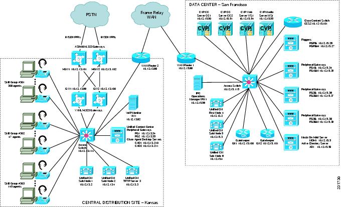
The following figure shows a typical high-level topology diagram for a two sites in a contact center network. Agents accepting calls from customers are located in a central distribution site in Kansas, while the equipment supporting interactive voice is located in a data center in San Francisco.
Synchronizing Server Date and Time
The best resources for diagnosing problems within your network are the debug and trace log files produced by individual Cisco devices. Tracing can be enabled on multiple devices and the log file output compared to isolate problems. To correlate messages for the same activity in different log files, compare the message time stamps and the source device MAC and IP addresses (there is no universal call ID value shared between Cisco devices). Synchronize every device to the same date and time source so that the time stamps match. To accomplish this synchronization, set each device to obtain its date and time from the same Network Time Protocol (NTP) source.
For Cisco IOS-based devices (switches, routers, or voice gateways), you can configure each device to act as an NTP client and periodically poll a master NTP source using the following command:
ntp server ip-address [version number] [key keyid] [source interface] [prefer]More IOS commands are available to establish a device as an NTP peer (operating as the master source for other devices), and setting up NTP broadcasting instead of polling. See the Using the Cisco IOS Command-Line Interface for details about these IOS commands.
Recommended Trace and Logging Settings
To have diagnostic information available when you begin to research problems, configure devices in your network to capture signaling, processing, and other activity in log files.
Cisco Unified Communications Manager Trace Settings
Trace settings for Cisco Unified Communications Manager servers are maintained using the Cisco Communications Manager Serviceability graphical interface. There are two ways to set trace logging levels for Unified Communications Manager services:
Customize trace levels for individual parameters: This approach offers a high-degree of control and flexibility over the trace output. To use this approach, you should understand not only the significance of each parameter, but also the impact of tracing on Unified Communications Manager server performance. For example, setting trace levels to “Error” has a minimal impact to CPU cycles while leaving the “Detail” level set for long periods of time may impact call processing. For instructions on setting individual trace levels, see the Cisco Unified Serviceability Administration Guide, “Configuring Trace” chapter.
Apply predefined trace levels: This approach allows you to quickly enable and disable tracing for each Unified Communications Manager service based on predefined levels. You can also use these default troubleshooting trace settings with customized settings to temporarily override your custom settings. For instructions on using the Troubleshooting Trace Settings option in the Cisco Unified Communications Manager Serviceability interface, see the Cisco Unified Serviceability Administration Guide, “Configuring Troubleshooting Trace Setting Configuration” chapter.
Debug Trace Settings for Unified IP IVR System
If you encounter any problems with the Unified CCX platform and Unified IP IVR system, activate the following debug trace settings to generate debug logs:
For Unified CCX platform issues: SS_TEL, SS_ICM, and LIB_ICM.
For JTAPI Client issues: Enable all Trace Levels and select all debug levels except MISC_DEBUGGING.
However, turn off the trace settings if you experience any degradation in performance during heavy load situations.
IVR Flowcharts
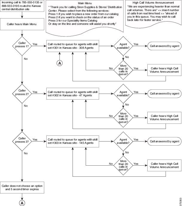
In a contact center environment, another tool that can help you troubleshoot call processing problems is a flowchart that traces the call routing process based on the interactive voice response (IVR) menu choices that callers make. traces the processing of an incoming call received by a central distribution site. The call receives a voice treatment prompting the call to select between three menu options or hold for an agent. The flowchart indicates which set of agents receives the call based on the menu option selected, and describes the capacity (number of agents) in the particular skill set group.
For calls received during high traffic periods, with more than 20 calls queued up for agents, the flowchart indicates that the announcements played to the callers and how the calls are routed. This type of flowchart is useful for troubleshooting problems reported by external users (customers). While shows a fairly simple example, where calls stay within a particular site, some contact center applications may overflow calls to other sites. In those cases, the overflow calls may traverse an IP WAN to a secondary site and may be handled by extra devices. In situations like that, view a network topology diagram for the secondary site to trace the call processing.
Conduct User Acceptance Test
After the components are configured and integrated with other Collaboration System applications, the field engineer prepares the system for the user acceptance test. Test scripts are run and compared against expected results. Any variability in network performance is noted and addressed before the user acceptance test.
Testing the customer solution involves the following tasks:
-
Determine the user acceptance test parameters and deliverables and record these in the user acceptance test plan.
-
Conduct a prelaunch test—Using an incremental approach, test the solution against the system design in a low-risk environment with limited users. If the system is stable, the rollout pace is increased until the full implementation is operational.
-
The customer signs the Ready-for-Use Acceptance Letter acknowledging that the acceptance test yielded satisfactory results.
Train Users
The final stage of the Implement phase is to help ensure that the customer’s system administration team and users are trained to take over management of the new system.
Cisco Systems offers several training and certification programs for customers to maximize the usage of their newly adopted systems. See Using the Training Library for more information on Cisco training websites and videos on demand (VODs).
 Feedback