Call Recording Examples for Network-Based and Phone-Based Recording
Recording Overview
This document contains use case examples and call flows for Cisco Unified Communications Manager's Call Recording feature.
Cisco Unified Communications Manager offers IP phone-based or network-based recording:
-
In IP phone based recording, recording media is sourced from the phone. The phone forks two media streams to the recording server.
-
In network-based recording, recording media can be sourced from either the phone or the gateway. When you implement network-based recording, the gateway in your network must connect to Cisco Unified Communications Manager over a SIP trunk.
Configuration
For more details on Call Recording, including configuration steps, see the "Recording" chapter of the Feature Configuration Guide for Cisco Unified Communications Manager for release 10.5(2) or greater at https://www.cisco.com/c/en/us/support/unified-communications/unified-communications-manager-callmanager/products-installation-and-configuration-guides-list.html. Note |
With Release 10.0(1), see the "Monitoring and Recording" chapter of the Features and Services Guide for Cisco Unified Communications Manager. |
Network-Based Recording Call Flow Examples
This section contains network-based recording call flow examples.
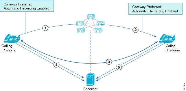
IP Phone to IP Phone - Both Enabled For Recording
In this use case, Gateway is preferred, but the phone is selected.
- 1–3. An IP phone calls another IP phone
- 4–5. Two recording sessions are started automatically from both IP phones. The recording media source for both phones is Gateway Preferred. Since the gateway is not in the call flow Cisco Unified Communications Manager selects the IP Phones to fork the media to the recorder.
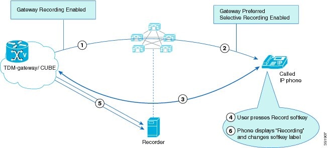
External Call to IP phone – Selective Recording
In this use case, Gateway is preferred and selected.
- 1–3. An external call is answered by a user with a Cisco IP phone.
- 4–5. The Cisco IP phone presses the Record softkey thereby starting a new recording session. The gateway is configured as the preferred recording media source and the gateway is valid for the call flow. Cisco Unified Communications Manager selects the gateway to fork the media to the recorder.
- 6. The Cisco IP phone displays "Recording…" and the softkey label changes to " StopRec".
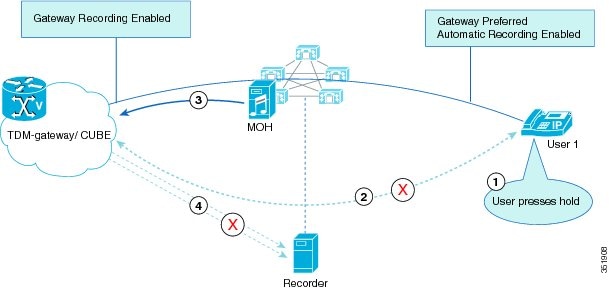
Mid-Call - Gateway Recording Session Stops When Call is Held
This use case demonstrates the Hold function on the IP phone.
- 1–3. A call is in progress and the gateway is recording the media. User 1 places the call on hold. Cisco Unified Communications Manager plays Music-on-Hold to the caller.
- 4. Cisco Unified Communications Manager instructs the gateway to stop forking media to the recorder.
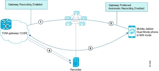
Mobility - External Call to Mobile Jabber Client
In this use case, the gateway is preferred and selected.
- 1–3. An external call is answered on a Mobile phone configured as a Dual-mode device
- 4. The recording session starts automatically for the dual mobile phone. The gateway is configured as the preferred recording source and is valid for the call flow. Cisco Unified Communications Manager selects the gateway to fork the media to the recorder.
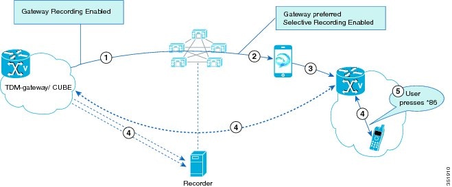
Mobility - External Call to Remote Destination Profile
In this use case, gateway is preferred and selected.
- 1–4. An external call is answered on a mobile phone using a remote destination configured on a Remote Destination Profile.
- 5–6. The mobile presses *86 to use DTMF to start the recording session. Cisco Unified Communications Manager selects the ingress gateway to fork the media to the recorder.
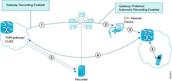
Extend and Connect - External Call to CTI Remote Device
In this use case, gateway is preferred and selected.
- 1–4. An external call is answered on an Extend & Connect remote destination that is configured as a CTI Remote Device.
- 5. The recording session starts from the CTI Remote Device. The gateway is configured as the preferred recording media source and is valid for the call flow. The ingress gateway is the first gateway in the call flow so Cisco Unified Communications Manager selects the ingress gateway to fork recording media to the recorder.
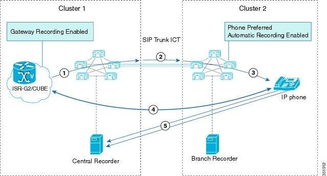
Inter-Cluster Recording - External Call From Cluster 1 to IP Phone on Cluster
In this use case, the gateway is selected. The Recording Profile specifies a central recorder.
- 1–4. An external call is received on a gateway in Cluster 1 and is answered by an IP phone in Cluster 2.
- 5. Recording starts automatically for the IP Phone in Cluster 2; the Phone is selected to fork the media. The recording profile assigned to the IP Phone is configured to use a central recorder.
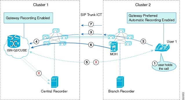
Inter-Cluster Recording – External Call From Cluster 1 Is HELD by User on Cluster 2
This use case demonstrates a mid-call Hold in an inter-cluster call.
- 1–5. An external call is underway to User 1 in Cluster 2. User 1 places the call on hold. The media stream is dropped.
- 6. Cisco Unified Communications Manager in Cluster 2 plays Music On Hold to the external caller.
- 7–8. Cisco Unified Communications Manager in Cluster 2 requests that Cluster 1 stop the recording session. Cluster 1 instructs the gateway to stop the session.
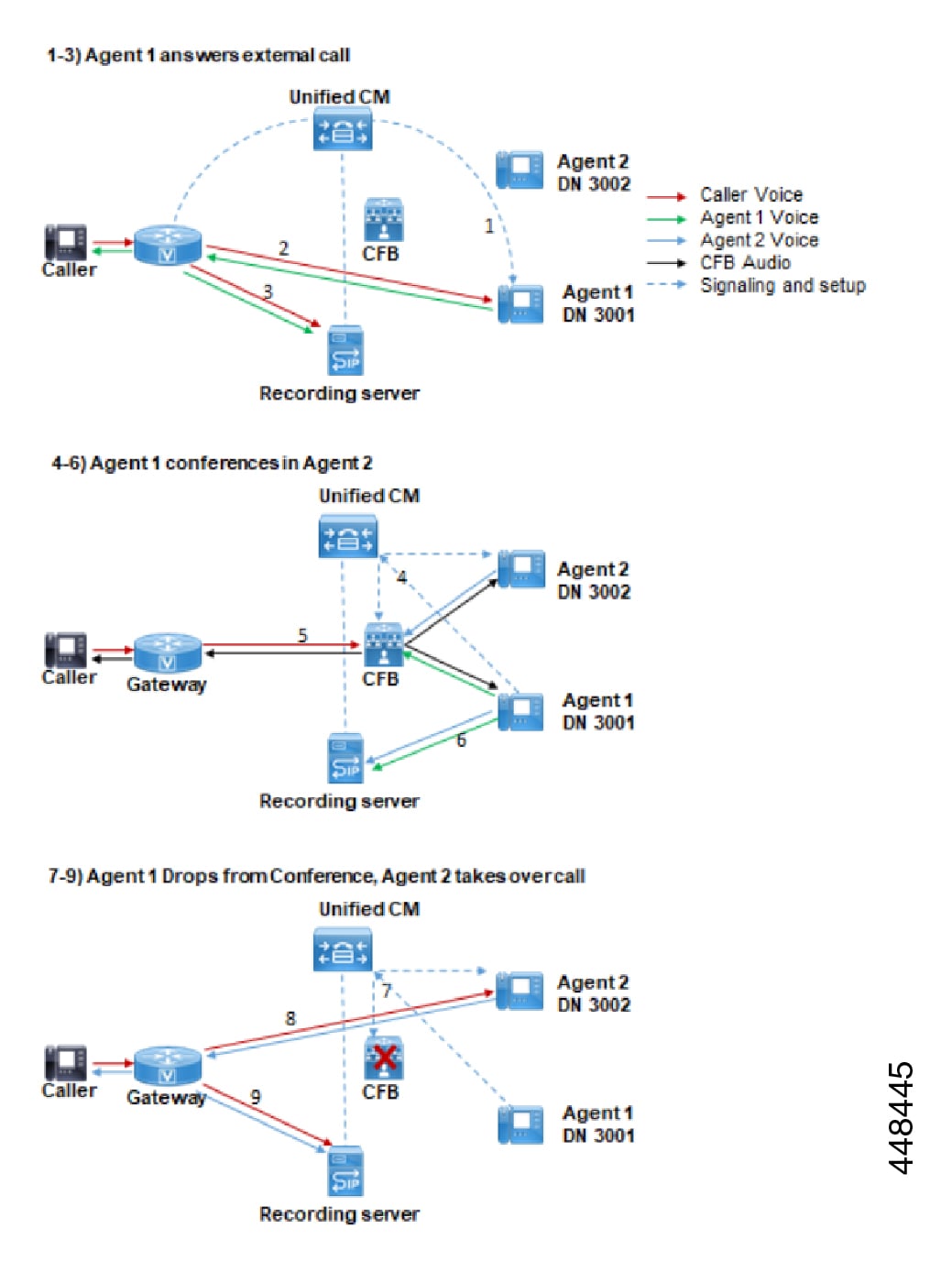
Three-Way Conference - Automatic Recording
This scenario illustrates a single network-based recording example with a three-way conference. Automatic recording is configured with the gateway as the preferred recording source. This single call flow requires three separate recording sessions, each for separate segments of the call.
First Recording – Agent 1 answers external call
-
External caller calls into enterprise. Agent 1 answers
-
Agent 1 has 1x1 conversation with caller
-
Gateway forks recording media to a recording server
Second Recording – Three-way conference
-
Agent 1 presses Conference and adds Agent 2. Initial recording session ends.
-
Three-way conference is set up between Agent 1, Agent 2 and external caller.
-
Agent 1’s phone BiB forks media to a recording server.
Third Recording – Agent 1 drops, Agent 2 takes over
-
Agent 1 drops from call, ending the conference and BiB recording session
-
Agent 2 takes over call with a 1x1 call with external Caller.
-
Gateway forks recording media to recording server.
Explanation for BiB recording in 4-6 even though Gateway is Preferred
Phone-based BIB recording is used when the call is conferenced (recording session 2) because the call media no longer travels between the phone and gateway directly. Instead, media travels between the gateway and conference bridge (CFB) and between the conference bridge and agent phones. Since Unified CM call recording is configured for an agent's phone line and cannot be initiated on the conference bridge, phone-based BiB recording is used for the conferencing portion.
IP Phone-Based Recording Call Flow Examples
This section contains network-based recording call flow examples.
Automatic Call Recording
In automatic call recording, after an agent call becomes active, two server calls get made to the built-in bridge (BIB) of the agent phone. The agent phone automatically answers. Two server calls then get redirected to the recorder.
The following figure illustrates automatic call recording.
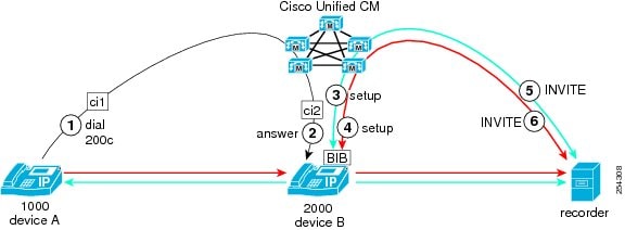
In this example of an automatic call recording session, the following entities participate:
-
The customer call originates from DN1000 deviceA.
-
The agent receives the call at DN2000 deviceB.
During an automatic call recording session, the following steps take place:
-
A customer, partyA (the far-end party) with DN1000, calls into the call center.
-
The call routes to the agent, who is partyB with DN2000. The agent answers the call. The agent IP phone starts to exchange media streams with the customer.
-
Because the agent line appearance is configured for automatic recording, the recording session for the media streams automatically gets triggered. Cisco Unified Communications Manager first makes a recording call to the built-in bridge (BIB) of the agent IP phone for the agent voice.
-
Cisco Unified Communications Manager makes the second recording call to the BIB of the agent IP phone for the customer voice.
-
The recorder receives and answers the recording call setup messages that are sent from Cisco Unified Communications Manager for the agent voice through a SIP trunk. The agent IP phone starts to fork the agent voice stream to the recorder.
-
The recorder receives and answers the recording call setup messages that the Cisco Unified Communications Manager sends for the customer voice through a SIP trunk. The agent IP phone starts to fork the customer voice stream to the recorder.
In previous releases, the INVITE message contained only near-end information, but customer information was unknown. A CTI connection to Cisco Unified Communications Manager was required to obtain the customer information.
The two INVITE messages for the two separate voice streams contain the same near-end and far-end call information. The only difference in the two From headers is the first x-parameter, which indicates whether the call is for the near-end voice stream or for the far-end voice stream. X-nearend indicates the near-end voice stream. X-farend indicates the far-end voice stream.
The INVITE message that is explained here (another INVITE message gets sent) contains the agent recording call.
Note |
|
Step 5 INVITE Message Header Information
From: <sip:2000@ucm1;x-nearend;x-refci=ci2;x-nearenddevice=deviceB;
 x-farendrefci=ci1;x-farenddevice=deviceA;x-farendaddr=1000>;tag=fromtag1
Step 6 INVITE Message Header Information
From: <sip:2000@ucm1;x-farend;x-refci=ci2;x-nearenddevice=deviceB;
x-farendrefci=ci1;x-farenddevice=deviceA;x-farendaddr=1000>;tag=fromtag2
In both message headers,
x-farendrefci specifies the far-end
(customer) call leg caller ID.
x-farenddevice specifies the far-end
device name.
x-farendaddr specifies the far-end
DN.
Local Cluster Far-End Party Hold/Resume
In this use case for automatic call recording, the far-end party that belongs to the local cluster places the call on hold and resumes the call from a different device. The following figure illustrates this use case.
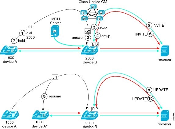
In this use case, the following entities participate:
-
The customer call originates from DN1000 deviceA.
-
The agent receives the call at DN2000 deviceB.
-
After placing the call on hold, the customer resumes the call from DN1000 deviceA’.
During an automatic call recording session that involves a customer (far-end party) in the local cluster that places the call on hold then resumes the call from a different device, the following steps take place:
-
PartyA (far-end party = customer in local cluster) calls partyB (near-end party = agent).
-
PartyB answers the call.
-
Because the agent line appearance is configured for automatic recording, the recording session for the media streams automatically gets triggered. Cisco Unified Communications Manager first makes a recording call to the built-in bridge (BIB) of the agent IP phone for the agent voice.
-
Cisco Unified Communications Manager makes the second recording call to the BIB of the agent IP phone for the customer voice.
-
The recorder receives and answers the recording call setup messages that are sent from Cisco Unified Communications Manager for the agent voice through a SIP trunk. The agent IP phone starts to fork the agent voice stream to the recorder.
-
The recorder receives and answers the recording call setup messages that are sent from Cisco Unified Communications Manager for the customer voice through a SIP trunk. The agent IP phone starts to fork the customer voice stream to the recorder.
-
PartyA (far-end party = customer in local cluster) places the call on hold.
-
PartyA (far-end party = customer in local cluster) resumes the held call from deviceA’ (a different device with same DN). Upon call resumption, partyB is now connected to the new far-end partyA’. The far-end call information has changed.
-
The recorder receives and answers the recording call UPDATE message that is sent from Cisco Unified Communications Manager for the agent voice through a SIP trunk. The agent IP phone forks the agent voice stream to the recorder.
-
The recorder receives and answers the recording call UPDATE message that is sent from Cisco Unified Communications Manager for the customer voice through a SIP trunk. The agent IP phone forks the customer voice stream to the recorder.
Note the following particularities of call processing that apply in this use case:
-
Insertion of MOH when the far-end party places the call on hold does not cause a change in the far-end party.
-
When another device that shares the line resumes the call, a SIP UPDATE message gets sent to the recorder with the new far-end party device name.
The UPDATE message that is explained here contains the agent (near-end) recording call. The other UPDATE for the customer (far-end) recording call contains the same information for the x-farend.
Note the header information of the INVITE message from step5 and the UPDATE message from step9. The SIP header enhancement feature adds the information in bold text to the message headers.
Step 5 INVITE Message Header Information
From: <sip:2000@ucm1;x-nearend;x-refci=ci2;x-nearenddevice=deviceB;
x-farendrefci=ci1;x-farenddevice=deviceA;x-farendaddr=1000>;tag=fromtag1
Step 9 UPDATE Message Header Information
From: <sip:2000@ucm1;x-nearend;x-refci=ci2;x-nearenddevice=deviceB;
x-farendrefci=ci1;x-farenddevice=deviceA’;x-farendaddr=1000>;tag=fromtag1
Far-End Party Transfers Call to Another Far-End Party in Local Cluster
In this use case for automatic call recording, the far-end party in the local cluster transfers the call to another far-end party in the same local cluster. The following figure illustrates this use case.
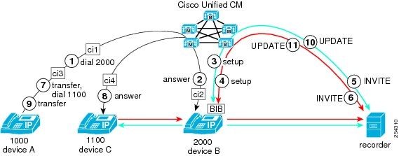
In this use case, the following entities participate:
-
The customer call originates from DN1000 deviceA in the local cluster.
-
The agent receives the call at DN2000 deviceB.
-
The customer transfers the call to DN1100 deviceC in the same local cluster.
During an automatic call recording session that involves a customer (far-end party) in the local cluster that places the call to the agent and then later transfers the call to another far-end party in the local cluster, the following steps take place:
-
PartyA (far-end party = customer in local cluster) calls partyB (near-end party = agent).
-
PartyB answers the call.
-
Because the agent line appearance is configured for automatic recording, the recording session for the media streams automatically gets triggered. Cisco Unified Communications Manager first makes a recording call to the built-in bridge (BIB) of the agent IP phone for the agent voice.
-
Cisco Unified Communications Manager makes the second recording call to the BIB of the agent IP phone for the customer voice.
-
The recorder receives and answers the recording call setup messages that are sent from Cisco Unified Communications Manager for the agent voice through a SIP trunk. The agent IP phone starts to fork the agent voice stream to the recorder.
-
The recorder receives and answers the recording call setup messages that are sent from Cisco Unified Communications Manager for the customer voice through a SIP trunk. The agent IP phone starts to fork the customer voice stream to the recorder.
-
PartyA (far-end party = customer in local cluster) initiates a consultation transfer of the call to another party, partyC at DN1100, in the local cluster.
-
PartyC answers the transferred call.
-
PartyA completes the transfer.
-
Because partyB is now connected to a new far-end party, partyC, Cisco Unified Communications Manager sends two UPDATE messages to the recorder.
-
The recorder receives and answers the recording call UPDATE message that is sent from Cisco Unified Communications Manager for the agent voice through a SIP trunk. The agent IP phone forks the agent voice stream to the recorder.
-
The recorder receives and answers the recording call UPDATE message that is sent from Cisco Unified Communications Manager for the customer voice through a SIP trunk. The agent IP phone forks the customer voice stream to the recorder.
Note the following particularities of call processing that apply in this use case:
-
After first press of the Transfer key, because no change in the far-end party information occurs, Cisco Unified Communications Manager does not update the recorder.
-
After the second press of the Transfer key, Cisco Unified Communications Manager sends the SIP UPDATE message to the recorder with updated far-end party information.
Note the following particularities of call processing that apply in this use case:
-
Insertion of MOH when the far-end party places the call on hold does not cause a change in the far-end party.
-
When another device that shares the line resumes the call, a SIP UPDATE message gets sent to the recorder with the new far-end party device name.
Note the header information of the INVITE message from step5 and the UPDATE message from step10. The SIP header enhancement feature adds the information in bold text to the message headers.
Step 5 INVITE Message Header Information
From: <sip:2000@ucm1;x-nearend;x-refci=ci2;x-nearenddevice=deviceB;
x-farendrefci=ci1;x-farenddevice=deviceA;x-farendaddr=1000>;tag=fromtag1
Step 10 UPDATE Message Header Information
From: <sip:2000@ucm1;x-nearend;x-refci=ci2;x-nearenddevice=deviceB;
x-farendrefci=ci4;x-farenddevice=deviceC;x-farendaddr=1100>;tag=fromtag1
When you compare the INVITE message header in step 5 with the UPDATE message header in step10, notice that the far-end values (farendrefci, farenddevice, and farendaddr) all change because of the transfer.
Near-End Party Transfers Call to Another Near-End Party in Local Cluster
In this use case for automatic call recording, the near-end party transfers a call to another near-end party in the local cluster. The following figure illustrates this use case.
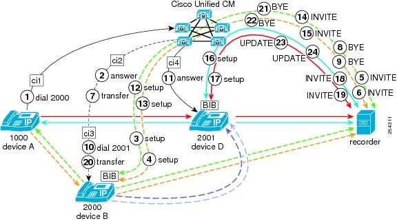
In this use case, the following entities participate:
-
The customer call originates from DN1000 deviceA.
-
The agent receives the call at DN2000 deviceB.
-
The agent transfers the call to DN2001 deviceD.
During an automatic call recording session where the agent on the call transfers the call to another party in the same local cluster, the following steps take place:
-
PartyA (far-end party = customer in local cluster) calls partyB (near-end party = agent).
-
PartyB (near-end party = agent in local cluster) answers the call.
-
Because the agent line appearance is configured for automatic recording, the recording session for the media streams automatically gets triggered. Cisco Unified Communications Manager first makes a recording call to the built-in bridge (BIB) of the agent IP phone for the agent voice.
-
Cisco Unified Communications Manager makes the second recording call to the BIB of the agent IP phone for the customer voice.
-
The recorder receives and answers the recording call setup messages that are sent from Cisco Unified Communications Manager for the agent voice through a SIP trunk. The agent IP phone starts to fork the agent voice stream to the recorder.
-
The recorder receives and answers the recording call setup messages that are sent from Cisco Unified Communications Manager for the customer voice through a SIP trunk. The agent IP phone starts to fork the customer voice stream to the recorder.
-
PartyB initiates the consultation transfer. This action implicitly places the call on hold.
-
Cisco Unified Communications Manager terminates recording of the agent voice by sending a BYE message to the recorder through a SIP trunk.
-
Cisco Unified Communications Manager terminates recording of the customer voice by sending a BYE message to the recorder through a SIP trunk.
-
PartyB calls partyD (another far-end party = agent in local cluster).
-
PartyD answers the call from partyB.
-
Because the agent line appearance is configured for automatic recording, the recording session for the media streams automatically gets triggered. Cisco Unified Communications Manager makes a recording call to the built-in bridge (BIB) of the partyB IP phone for the agent voice.
-
Cisco Unified Communications Manager makes the second recording call to the BIB of the partyB IP phone for the customer voice.
-
The recorder receives and answers the recording call setup messages that are sent from Cisco Unified Communications Manager for the partyB (agent) voice through a SIP trunk. The agent IP phone starts to fork the agent voice stream to the recorder.
-
The recorder receives and answers the recording call setup messages that are sent from Cisco Unified Communications Manager for the partyA (customer) voice through a SIP trunk. The agent IP phone starts to fork the customer voice stream to the recorder.
-
Because the agent line appearance is configured for automatic recording, the recording session for the media streams automatically gets triggered. Cisco Unified Communications Manager makes a recording call to the built-in bridge (BIB) of the partyD IP phone for the agent voice.
-
Cisco Unified Communications Manager makes the second recording call to the BIB of the partyD IP phone for the customer voice.
-
The recorder receives and answers the recording call setup messages that are sent from Cisco Unified Communications Manager for the partyD (agent) voice through a SIP trunk. The agent IP phone starts to fork the agent voice stream to the recorder.
-
The recorder receives and answers the recording call setup messages that are sent from Cisco Unified Communications Manager for the partyA (customer) voice through a SIP trunk. The agent IP phone starts to fork the customer voice stream to the recorder.
-
PartyB completes the transfer.
-
Cisco Unified Communications Manager terminates recording of the partyB (agent) voice (the consultation call) by sending a BYE message to the recorder through a SIP trunk.
-
Cisco Unified Communications Manager terminates recording of the partyA (customer) voice by sending a BYE message to the recorder through a SIP trunk.
-
Because partyD is now connected to a new far-end party, partyA, Cisco Unified Communications Manager sends two UPDATE messages to the recorder.
-
The recorder receives and answers the recording call UPDATE message that is sent from Cisco Unified Communications Manager for the partyD (agent) voice through a SIP trunk. The agent IP phone forks the agent voice stream to the recorder.
-
The recorder receives and answers the recording call UPDATE message that is sent from Cisco Unified Communications Manager for the partyA (customer) voice through a SIP trunk. The agent IP phone forks the customer voice stream to the recorder.
Note the following particularities of call processing that apply in this use case:
-
When the near-end partyB presses Transfer, the call is implicitly put on hold, and the recording session with partyA terminates.
-
When partyB dials partyD and partyD answers, a new recording session starts for partyD.
-
When partyB completes the transfer, partyD and partyA get connected and the recorder receives an update with information about the new far-end partyA.
Generally, each time an agent puts a recording call on hold, the current recording session terminates. Each time the agent invokes a supplementary service, such as Transfer or hold, the call is implicitly put on hold. Each time the far-end information changes, Cisco Unified Communications Manager sends a SIP UPDATE message to the recorder.
Note the header information of the INVITE messages from step5, step14, step18, and the UPDATE message from step23. The SIP header enhancement feature adds the information in bold text to the message headers.
Step 5 INVITE Message Header Information
From: <sip:2000@ucm1;x-nearend;x-refci=ci2;x-nearenddevice=deviceB;
x-farendrefci=ci1;x-farenddevice=deviceA;x-farendaddr=1000>;tag=fromtag1
Step 14 INVITE Message Header Information
From: <sip:2000@ucm1;x-nearend;x-refci=ci3;x-nearenddevice=deviceB;
x-farendrefci=ci4;x-farenddevice=deviceD;x-farendaddr=2001>;tag=fromtag2
Step 18 INVITE Message Header Information
From: <sip:2001@ucm1;x-nearend;x-refci=ci4;x-nearenddevice=deviceD;
x-farendrefci=ci3;x-farenddevice=deviceB;x-farendaddr=2000>;tag=fromtag2
Step 23 UPDATE Message Header Information
From: <sip:2001@ucm1;x-nearend;x-refci=ci4;x-nearenddevice=deviceD;
x-farendrefci=ci1;x-farenddevice=deviceA;x-farendaddr=1000>;tag=fromtag2
Far-End Party Transfers Call to CFNA-Enabled Party
In this use case for automatic call recording, the far-end party blind-transfers the call to a party that has Call Forward No Answer (CFNA) enabled. The following figure illustrates this use case.
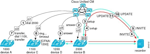
In this use case, the following entities participate:
-
The customer call originates from DN1000 deviceA.
-
The agent receives the call at DN2000 deviceB.
-
The customer blind-transfers the call to DN1100 deviceC.
-
DeviceC does not answer but has CFNA enabled to forward to DN1200 deviceD.
During an automatic call recording session where the far-end party (customer) on the call transfers the call to another far-end party in the same local cluster but the far-end party has CFNA enabled, so the call forwards to a third far-end party in the local cluster, the following steps take place:
-
PartyA (far-end party = customer in local cluster) calls partyB (near-end party = agent).
-
PartyB (near-end party = agent in local cluster) answers the call.
-
Because the agent line appearance is configured for automatic recording, the recording session for the media streams automatically gets triggered. Cisco Unified Communications Manager first makes a recording call to the built-in bridge (BIB) of the partyB (agent) IP phone for the agent voice.
-
Cisco Unified Communications Manager makes the second recording call to the BIB of the partyB (agent) IP phone for the customer voice.
-
The recorder receives and answers the recording call setup messages that are sent from Cisco Unified Communications Manager for the agent voice through a SIP trunk. The agent IP phone starts to fork the agent voice stream to the recorder.
-
The recorder receives and answers the recording call setup messages that are sent from Cisco Unified Communications Manager for the customer voice through a SIP trunk. The agent IP phone starts to fork the customer voice stream to the recorder.
-
PartyA presses Transfer, dials DN1100 deviceC, and presses Transfer again (performs a blind transfer).
-
Cisco Unified Communications Manager rings DN1100 on deviceC, but this DN and device have CFNA configured: ringing times out, and Cisco Unified Communications Manager forwards the call to DN1200 deviceD.
-
Far-end partyD with DN1200 on deviceD answers the call.
-
Because partyB is now connected to a new far-end party, partyD, Cisco Unified Communications Manager sends two UPDATE messages to the recorder.
-
The recorder receives and answers the recording call UPDATE message that is sent from Cisco Unified Communications Manager for the partyB (agent) voice through a SIP trunk. The agent IP phone forks the agent voice stream to the recorder.
-
The recorder receives and answers the recording call UPDATE message that is sent from Cisco Unified Communications Manager for the partyD (customer) voice through a SIP trunk. The agent IP phone forks the customer voice stream to the recorder.
Note the following particularities of call processing that apply in this use case:
-
For local-cluster transfers, Cisco Unified Communications Manager updates the recorder only when a new far-end party answers.
-
A SIP UPDATE message that contains updated far-end information gets sent to the recorder when partyD answers.
Note the header information of the INVITE messages from step5 and step10. The SIP header enhancement feature adds the information in bold text to the INVITE and UPDATE message headers.
Step 5 INVITE Message Header Information
From: <sip:2000@ucm1;x-nearend;x-refci=ci2;x-nearenddevice=deviceB;
x-farendrefci=ci1;x-farenddevice=deviceA;x-farendaddr=1000>;tag=fromtag1
Step 10 UPDATE Message Header Information
From: <sip:2000@ucm1;x-nearend;x-refci=ci2;x-nearenddevice=deviceB;
x-farendrefci=ci5;x-farenddevice=deviceD;x-farendaddr=1200>;tag=fromtag1
Far-End Party in Local Cluster Creates Conference
In this use case for automatic call recording, the far-end party in a local cluster creates a conference. The following figure illustrates this use case.
In this use case, the following entities participate:
-
The far-end customer call originates from DN1000 deviceA.
-
The near-end agent receives the call at DN2000 deviceB.
-
PartyA creates a conference by conferencing in DN1100 deviceC.
During an automatic call recording session where the far-end (customer) party in the local cluster creates a conference by bringing an additional far-end party into the call, the following steps take place:
-
PartyA (far-end party = customer in local cluster) calls partyB (near-end party = agent).
-
PartyB (near-end party = agent in local cluster) answers the call.
-
Because the agent line appearance is configured for automatic recording, the recording session for the media streams automatically gets triggered. Cisco Unified Communications Manager first makes a recording call to the built-in bridge (BIB) of the partyB (agent) IP phone for the agent voice.
-
Cisco Unified Communications Manager makes the second recording call to the BIB of the partyB (agent) IP phone for the customer voice.
-
The recorder receives and answers the recording call setup messages that are sent from Cisco Unified Communications Manager for the agent voice through a SIP trunk. The agent IP phone starts to fork the partyB (agent) voice stream to the recorder.
-
The recorder receives and answers the recording call setup messages that are sent from Cisco Unified Communications Manager for the customer voice through a SIP trunk. The agent IP phone starts to fork the partyA (customer) voice stream to the recorder.
-
PartyA initiates a conference by pressing Confn and dialing DN1100.
-
PartyC DN1100 deviceC answers the call.
-
PartyA completes the conference by pressing Confn again.
-
Because partyB is now connected to a new far-end party, CFB_2, Cisco Unified Communications Manager sends two UPDATE messages to the recorder.
-
The recorder receives and answers the recording call UPDATE message that is sent from Cisco Unified Communications Manager for the partyB (agent) voice through a SIP trunk. The agent IP phone forks the agent voice stream to the recorder.
-
The recorder receives and answers the recording call UPDATE message that is sent from Cisco Unified Communications Manager for CFB_2 (conference bridge) through a SIP trunk. The agent IP phone forks the conference voice stream to the recorder.
Note the following particularities of call processing that apply in this use case:
-
After the conference gets established, the far-end party is changed to the conference bridge (CFB).
-
Cisco Unified Communications Manager sends a SIP UPDATE message to the recorder.
Note the header information of the INVITE messages from step5 and step10. The SIP header enhancement feature adds the information in bold text to the INVITE message headers.
Step 5 INVITE Message Header Information
From: <sip:2000@ucm1;x-nearend;x-refci=ci2;x-nearenddevice=deviceB;
x-farendrefci=ci1;x-farenddevice=deviceA;x-farendaddr=1000>;tag=fromtag1
Step 10 UPDATE Message Header Information
From: <sip:2000@ucm1;x-nearend;x-refci=ci2;x-nearenddevice=deviceB;
x-farendrefci=ci7;x-farenddevice=CFB_2;x-farendaddr=b001234567;isfocus>;tag=fromtag1
The UPDATE message in step10 includes isfocus. This isfocus indicates that the near-end party is participating in a conference call. The UPDATE message also includes a b-number as the new far-end address. The b-number specifies the DN of the conference bridge (CFB).
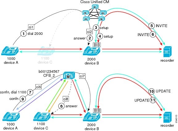
Near-End Party in Local Cluster Creates Conference
In this use case for automatic call recording, the near-end party in a local cluster creates a conference. The following figure illustrates this use case.
In this use case, the following entities participate:
-
The far-end customer call originates from DN1000 deviceA.
-
The near-end agent receives the call at DN2000 deviceB.
-
PartyB creates a conference by conferencing in DN1100 deviceC.
During an automatic call recording session where the near-end (agent) party in the local cluster creates a conference by bringing an additional far-end party into the call, the following steps take place:
-
PartyA (far-end party = customer in local cluster) calls partyB (near-end party = agent).
-
PartyB (near-end party = agent in local cluster) answers the call.
-
Because the agent line appearance is configured for automatic recording, the recording session for the media streams automatically gets triggered. Cisco Unified Communications Manager first makes a recording call to the built-in bridge (BIB) of the partyB (agent) IP phone for the agent voice.
-
Cisco Unified Communications Manager makes the second recording call to the BIB of the partyB (agent) IP phone for the customer voice.
-
The recorder receives and answers the recording call setup messages that are sent from Cisco Unified Communications Manager for the agent voice through a SIP trunk. The agent IP phone starts to fork the partyB (agent) voice stream to the recorder.
-
The recorder receives and answers the recording call setup messages that are sent from Cisco Unified Communications Manager for the customer voice through a SIP trunk. The agent IP phone starts to fork the partyA (customer) voice stream to the recorder.
-
PartyB, the near-end party, initiates a conference by pressing Confn. When the near-end party makes a consultation call for a conference participant, the near-end party call automatically gets put on hold.
-
Cisco Unified Communications Manager terminates recording of the partyB (agent) voice (the consultation call) by sending a BYE message to the recorder through a SIP trunk.
-
Cisco Unified Communications Manager terminates recording of the partyA (customer) voice by sending a BYE message to the recorder through a SIP trunk.
-
Near-end partyB dials DN1100 partyC.
-
PartyC answers the call.
-
Because the agent line appearance is configured for automatic recording, the recording session for the media streams automatically gets triggered. Cisco Unified Communications Manager makes a recording call to the built-in bridge (BIB) of the partyB IP phone for the near-end (agent) voice.
-
Cisco Unified Communications Manager makes the second recording call to the BIB of the partyB IP phone for the far-end (customer) voice.
-
The recorder receives and answers the recording call setup messages that are sent from Cisco Unified Communications Manager for the partyB (agent) voice through a SIP trunk. The agent IP phone starts to fork the near-end (agent) voice stream to the recorder.
-
The recorder receives and answers the recording call setup messages that are sent from Cisco Unified Communications Manager for the far-end (customer) voice through a SIP trunk. The agent IP phone starts to fork the customer voice stream to the recorder.
-
PartyB completes the consultation conference by pressing Confn. All parties connect to the conference bridge (CFB_2).
-
Because partyB is now connected to a new far-end party, CFB_2, Cisco Unified Communications Manager sends two UPDATE messages to the recorder.
-
The recorder receives and answers the recording call UPDATE message that is sent from Cisco Unified Communications Manager for the partyB (agent) voice through a SIP trunk. The agent IP phone forks the agent voice stream to the recorder.
-
The recorder receives and answers the recording call UPDATE message that is sent from Cisco Unified Communications Manager for CFB_2 (conference bridge) through a SIP trunk. The agent IP phone forks the conference voice stream to the recorder.
Note the following particularities of call processing that apply in this use case:
-
Near-end party creates a conference; the first recording session gets torn down
-
Connection of the consultation call re-establishes the recording session.
-
Far-end party changes to CFB and Cisco Unified Communications Manager sends SIP UPDATE message to the recorder.
Note the header information of the INVITE messages from step5 and step14, and the UPDATE message from step17. The SIP header enhancement feature adds the information in bold text to the INVITE and UPDATE message headers.
Step 5 INVITE Message Header Information
From: <sip:2000@ucm1;x-nearend;x-refci=ci2;x-nearenddevice=deviceB;
x-farendrefci=ci1;x-farenddevice=deviceA;x-farendaddr=1000>;tag=fromtag1
Step 14 INVITE Message Header Information
From: <sip:2000@ucm1;x-nearend;x-refci=ci3;x-nearenddevice=deviceB;
x-farendrefci=ci4;x-farenddevice=deviceC;x-farendaddr=1100>;tag=fromtag1
Step 17 UPDATE Message Header Information
From: <sip:2000@ucm1;x-nearend;x-refci=ci2;x-nearenddevice=deviceB;
x-farendrefci=ci7;x-farenddevice=CFB_2;x-farendaddr=B001234567;isfocus>;tag=fromtag1
The UPDATE message in step17 includes isfocus. This isfocus indicates that the near-end party is participating in a conference call. The UPDATE message also includes a b-number as the new far-end address. The b-number specifies the DN of the conference bridge (CFB).
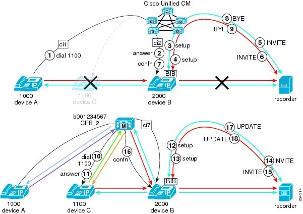
Far-End Party in Remote Cluster Transfers Call to Another Party
In this use case for automatic call recording, the far-end party in a remote cluster transfers the call to another party in the remote cluster. The following figure illustrates this use case.
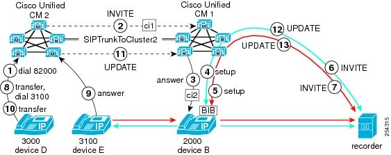
In this use case, the following entities participate:
-
The customer call originates from DN3000 deviceD in clusterCisco Unified CM2.
-
The agent receives the call at DN2000 deviceB in clusterCisco Unified CM1.
-
AgentD transfers the call to DN3100 deviceE in clusterCisco Unified CM2.
During an automatic call recording session where the far-end (agent) party in the remote cluster transfers the call to another party in the remote cluster, the following steps take place:
-
PartyD (far-end party = customer in remote cluster) calls partyB (near-end party = agent) in local cluster by dialing 82000.
-
The remote cluster (Cisco Unified CM2) sends an INVITE message to the local cluster (Cisco Unified CM1) through a SIP trunk. The message contains information about partyD.
-
PartyB (near-end party = agent in local cluster) answers the call.
-
Because the agent line appearance is configured for automatic recording, the recording session for the media streams automatically gets triggered. Cisco Unified Communications Manager first makes a recording call to the built-in bridge (BIB) of the partyB (agent) IP phone for the agent voice.
-
Cisco Unified Communications Manager makes the second recording call to the BIB of the partyB (agent) IP phone for the customer voice.
-
The recorder receives and answers the recording call setup messages that are sent from Cisco Unified Communications Manager for the agent voice through a SIP trunk. The agent IP phone starts to fork the partyB (agent) voice stream to the recorder.
-
The recorder receives and answers the recording call setup messages that are sent from Cisco Unified Communications Manager for the customer voice through a SIP trunk. The agent IP phone starts to fork the partyD (customer) voice stream to the recorder.
-
PartyD in the remote cluster initiates a transfer (presses Transfer) and dials DN3100 deviceE, which is also in the remote cluster.
-
PartyE answers the call.
-
PartyD completes the transfer by pressing Transfer.
-
The remote cluster (Cisco Unified CM2) sends an INVITE message to the local cluster (Cisco Unified CM1) through a SIP trunk. The message contains information about partyE.
-
Because partyB is now connected to a new far-end party, partyE, Cisco Unified Communications Manager sends two UPDATE messages to the recorder.
-
The recorder receives and answers the recording call UPDATE message that is sent from Cisco Unified Communications Manager for the partyB (agent) voice through a SIP trunk. The agent IP phone forks the agent voice stream to the recorder.
-
The recorder receives and answers the recording call UPDATE message that is sent from Cisco Unified Communications Manager for the partyE (customer) voice through a SIP trunk. The agent IP phone forks the customer voice stream to the recorder.
Note the following particularities of call processing that apply in this use case:
-
Far-end party and transfer-to party are both in the remote (Cisco Unified CM2) cluster. The near-end party sees the far-end party via the SIP trunk that links the two clusters.
-
When the transfer-to party answers, the recorder receives an UPDATE message that contains the far-end address.
Note the header information of the INVITE message from step6 and the UPDATE message from step12. The SIP header enhancement feature adds the information in bold text to the message headers.
Step 6 INVITE Message Header Information
From: <sip:2000@ucm1;x-nearend;x-refci=ci2;x-nearenddevice=deviceB;
x-farendrefci=ci1;x-farenddevice=SIPTrunkTocluster2;x-farendaddr=3000>;tag=fromtag1
Step 12 UPDATE Message Header Information
From: <sip:2000@ucm1;x-nearend;x-refci=ci2;x-nearenddevice=deviceB;
x-farendrefci=ci1;x-farenddevice=SIPTrunkTocluster2;x-farendaddr=3100>;tag=fromtag1
Far-End Party in Remote Cluster Blind-Transfers Call
In this use case for automatic call recording, the far-end party in the remote cluster blind-transfers the call to a remote party that does not answer and has Call Forward No Answer (CFNA) configured. The following figure illustrates this use case.
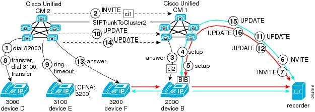
In this use case, the following entities participate:
-
The customer call originates from DN3000 deviceD in clusterCisco Unified CM2.
-
The agent receives the call at DN2000 deviceB in clusterCisco Unified CM1.
-
AgentD blind-transfers the call to DN3100 deviceE in clusterCisco Unified CM2.
-
AgentE does not answer and the call forwards to DN3200 deviceF in clusterCisco Unified CM2.
During an automatic call recording session where the far-end (agent) party in the remote cluster blind-transfers the call to another party in the remote cluster, but the second party does not answer and the call forwards to a third party in the remote cluster, the following steps take place:
-
PartyD (far-end party = customer in remote cluster) calls partyB (near-end party = agent) in local cluster by dialing 82000.
-
The remote cluster (Cisco Unified CM2) sends an INVITE message to the local cluster (Cisco Unified CM1) through a SIP trunk. The message contains information about partyD.
-
PartyB (near-end party = agent in local cluster) answers the call.
-
Because the agent line appearance is configured for automatic recording, the recording session for the media streams automatically gets triggered. Cisco Unified Communications Manager first makes a recording call to the built-in bridge (BIB) of the partyB (agent) IP phone for the agent voice.
-
Cisco Unified Communications Manager makes the second recording call to the BIB of the partyB (agent) IP phone for the customer voice.
-
The recorder receives and answers the recording call setup messages that are sent from Cisco Unified Communications Manager for the agent voice through a SIP trunk. The agent IP phone starts to fork the partyB (agent) voice stream to the recorder.
-
The recorder receives and answers the recording call setup messages that are sent from Cisco Unified Communications Manager for the customer voice through a SIP trunk. The agent IP phone starts to fork the partyD (customer) voice stream to the recorder.
-
PartyD in the remote cluster initiates a transfer (presses Transfer) and dials DN3100 deviceE, which is also in the remote cluster.
-
PartyE does not answer the call: ringing times out, so Cisco Unified Communications Manager sends the call to partyF DN3200 deviceF.
-
The remote cluster (Cisco Unified CM2) sends an UPDATE message to the local cluster (Cisco Unified CM1) through a SIP trunk. The message contains information about partyE.
-
Because partyB is now connecting to a new far-end party, partyE, local Cisco Unified Communications Manager sends two UPDATE messages to the recorder.
-
The recorder receives and answers the recording call UPDATE message that is sent from Cisco Unified Communications Manager for the partyB (agent) voice through a SIP trunk. The agent IP phone forks the agent voice stream to the recorder.
-
The recorder receives and answers the recording call UPDATE message that is sent from Cisco Unified Communications Manager for the partyE (customer) voice through a SIP trunk. The agent IP phone forks the customer voice stream to the recorder.
-
PartyF answers the forwarded call.
-
The remote cluster (Cisco Unified CM2) sends an UPDATE message to the local cluster (Cisco Unified CM1) through a SIP trunk. The message contains information about partyF.
-
Because partyB is now connected to a new far-end party, partyF, Cisco Unified Communications Manager sends two UPDATE messages to the recorder.
-
The recorder receives and answers the recording call UPDATE message that is sent from Cisco Unified Communications Manager for the partyB (agent) voice through a SIP trunk. The agent IP phone forks the agent voice stream to the recorder.
-
The recorder receives and answers the recording call UPDATE message that is sent from Cisco Unified Communications Manager for the partyF (customer) voice through a SIP trunk. The agent IP phone forks the customer voice stream to the recorder.
Note the following particularities of call processing that apply in this use case:
-
Far-end partD in remote cluster transfers call to partyE in remote cluster; the remote Cisco Unified Communications Manager updates the recorder.
-
PartyE CFNA timer expires and Cisco Unified Communications Manager redirects call to partyF; the remote Cisco Unified Communications Manager again updates the recorder.
-
The call state of the local Cisco Unified Communications Manager remains call-active, so Cisco Unified Communications Manager updates the recorder for each forwarded remote device.
Note the header information of the INVITE messages from step6, step11, and step15. The SIP header enhancement feature adds the information in bold text to the INVITE and UPDATE message headers.
Step 6 INVITE Message Header Information
From: <sip:2000@ucm1;x-nearend;x-refci=ci2;x-nearenddevice=deviceB;
x-farendrefci=ci1;x-farenddevice=SIPTrunkTocluster2;x-farendaddr=3000>;tag=fromtag1
Step 11 UPDATE Message Header Information
From: <sip:2000@ucm1;x-nearend;x-refci=ci2;x-nearenddevice=deviceB;
x-farendrefci=ci1;x-farenddevice=SIPTrunkTocluster2;x-farendaddr=3100>;tag=fromtag1
Step 15 UPDATE Message Header Information
From: <sip:2000@ucm1;x-nearend;x-refci=ci2;x-nearenddevice=deviceB;
x-farendrefci=ci1;x-farenddevice=SIPTrunkTocluster2;x-farendaddr=3200>;tag=fromtag1
Far-End Party in Remote PBX Transfers Call to Phone in Local Cluster
In this use case for automatic call recording, the far-end party in a remote PBX transfers a call to a phone in the local cluster. The following figure illustrates this use case.
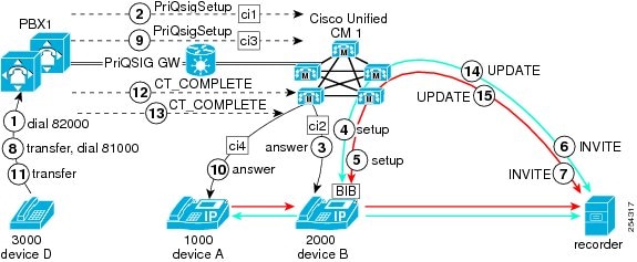
In this use case, the following entities participate:
-
The customer call originates from DN3000 deviceD in PBX1.
-
The agent receives the call at DN2000 deviceB in clusterCisco Unified CM1.
-
AgentD transfers the call to DN1000 deviceA in clusterCisco Unified CM1.
During an automatic call recording session where the far-end (agent) party in a remote PBX transfers the call to another party in the local cluster, the following steps take place:
-
PartyD (far-end party = customer in remote PBX) calls partyB (near-end party = agent) in local cluster by dialing 82000.
-
The remote PBX sends an setup message to the local cluster (Cisco Unified CM1) through a PRI QSIG gateway. The message contains information about partyD.
-
PartyB (near-end party = agent in local cluster) answers the call.
-
Because the agent line appearance is configured for automatic recording, the recording session for the media streams automatically gets triggered. Cisco Unified Communications Manager first makes a recording call to the built-in bridge (BIB) of the partyB (agent) IP phone for the agent voice.
-
Cisco Unified Communications Manager makes the second recording call to the BIB of the partyB (agent) IP phone for the customer voice.
-
The recorder receives and answers the recording call setup messages that are sent from Cisco Unified Communications Manager for the agent voice through a SIP trunk. The agent IP phone starts to fork the partyB (agent) voice stream to the recorder.
-
The recorder receives and answers the recording call setup messages that are sent from Cisco Unified Communications Manager for the customer voice through a SIP trunk. The agent IP phone starts to fork the partyD (customer) voice stream to the recorder.
-
PartyD in the remote PBX initiates a consultation transfer (presses Transfer) and dials DN81000 deviceA, which is in the local cluster.
-
The remote PBX sends an setup message to the local cluster (Cisco Unified CM1) through a PRI QSIG gateway. The message contains information about partyD.
-
PartyA answers the call from partyD.
-
PartyD presses Transfer to complete the transfer.
-
Remote PBX sends UPDATE.
-
Remote PBX sends UPDATE.
-
Because partyB is now connecting to a new far-end party, partyA, local Cisco Unified Communications Manager sends two UPDATE messages to the recorder.
-
The recorder receives and answers the recording call UPDATE message that is sent from local Cisco Unified Communications Manager for the partyB (agent) voice through a SIP trunk. The agent IP phone forks the agent voice stream to the recorder.
-
The recorder receives and answers the recording call UPDATE message that is sent from local Cisco Unified Communications Manager for the partyA (customer) voice. The agent IP phone forks the customer voice stream to the recorder.
Note the following particularities of call processing that apply in this use case:
-
When the far-end party in a remote cluster transfers the call to a party in the local cluster, Cisco Unified Communications Manager sends a SIP UPDATE message with farendaddr for the transferred-to local-cluster party.
-
This transfer specifies a hairpin transfer: the far-end address changed to the local DN1000 in the UPDATE message.
Note the header information of the INVITE messages from step6 and step14. The SIP header enhancement feature adds the information in bold text to the INVITE and UPDATE message headers.
Step 6 INVITE Message Header Information
From: <sip:2000@ucm1;x-nearend;x-refci=ci2;x-nearenddevice=deviceB;
x-farendrefci=ci1;x-farenddevice=PriQSIGGW;x-farendaddr=3000>;tag=fromtag1
Step 14 UPDATE Message Header Information
From: <sip:2000@ucm1;x-nearend;x-refci=ci2;x-nearenddevice=deviceB;
x-farendrefci=ci1;x-farenddevice=PriQSIGGW;x-farendaddr=1000>;tag=fromtag1
Remote PBX Far-End Party Transfers Call to Local Phone
In this use case for automatic call recording, a remote PBX far-end party transfers the call to a local phone by using path replacement. The following figure illustrates this use case.
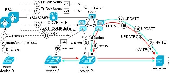
In this use case, the following entities participate:
-
The customer call originates from DN3000 deviceD in PBX1.
-
The agent receives the call at DN2000 deviceB in clusterCisco Unified CM1.
-
AgentD transfers the call to DN1000 deviceA in clusterCisco Unified CM1.
During an automatic call recording session where the far-end (agent) party in a remote PBX transfers the call to a phone in the local cluster by using path replacement, the following steps take place:
-
PartyD (far-end party = customer in remote PBX) calls partyB (near-end party = agent) in local cluster by dialing 82000.
-
The remote PBX sends an setup message to the local cluster (Cisco Unified CM1) through a PRI QSIG gateway. The message contains information about partyD.
-
PartyB (near-end party = agent in local cluster) answers the call.
-
Because the agent line appearance is configured for automatic recording, the recording session for the media streams automatically gets triggered. Cisco Unified Communications Manager first makes a recording call to the built-in bridge (BIB) of the partyB (agent) IP phone for the agent voice.
-
Cisco Unified Communications Manager makes the second recording call to the BIB of the partyB (agent) IP phone for the customer voice.
-
The recorder receives and answers the recording call setup messages that are sent from Cisco Unified Communications Manager for the agent voice through a SIP trunk. The agent IP phone starts to fork the partyB (agent) voice stream to the recorder.
-
The recorder receives and answers the recording call setup messages that are sent from Cisco Unified Communications Manager for the customer voice through a SIP trunk. The agent IP phone starts to fork the partyD (customer) voice stream to the recorder.
-
PartyD in the remote PBX initiates a consultation transfer (presses Transfer) and dials DN81000 deviceA, which is in the local cluster.
-
The remote PBX sends an setup message to the local cluster (Cisco Unified CM1) through a PRI QSIG gateway. The message contains information about partyD.
-
Local partyA answers the call from partyD.
-
Remote partyD presses Transfer to complete the transfer.
-
Remote PBX sends UPDATE.
-
Remote PBX sends UPDATE.
-
Because partyB is now connecting to a new far-end party, partyA, local Cisco Unified Communications Manager sends two UPDATE messages to the recorder.
-
The recorder receives and answers the recording call UPDATE message that is sent from local Cisco Unified Communications Manager for the partyB (agent) voice through a SIP trunk. The agent IP phone forks the agent voice stream to the recorder.
-
The recorder receives and answers the recording call UPDATE message that is sent from local Cisco Unified Communications Manager for the partyA (customer) voice. The agent IP phone forks the customer voice stream to the recorder.
-
Local Cisco Unified Communications Manager initiates path replacement process directly connects deviceA with device B and eliminates routing through the remote PBX.
-
Because partyB is now connecting to a new far-end party, partyA, local Cisco Unified Communications Manager sends two UPDATE messages to the recorder.
-
The recorder receives and answers the recording call UPDATE message that is sent from local Cisco Unified Communications Manager for the partyB (agent) voice through a SIP trunk. The agent IP phone forks the agent voice stream to the recorder.
-
The recorder receives and answers the recording call UPDATE message that is sent from local Cisco Unified Communications Manager for the partyA (customer) voice. The agent IP phone forks the customer voice stream to the recorder.
Note the following particularities of call processing that apply in this use case:
-
Path replacement replaces a hairpin call to remote PBX so that partyA and partyB are directly connected without routing through the remote PBX.
-
The far-end call information gets updated when transfer completes.
-
When path replacement completes, the far-end device also gets updated.
Note the header information of the INVITE messages from step6, step14, and step17. The SIP header enhancement feature adds the information in bold text to the INVITE and UPDATE message headers.
Step 6 INVITE Message Header Information
From: <sip:2000@ucm1;x-nearend;x-refci=ci2;x-nearenddevice=deviceB;
x-farendrefci=ci1;x-farenddevice=PriQSIGGW;x-farendaddr=3000>;tag=fromtag1
Step 14 UPDATE Message Header Information
From: <sip:2000@ucm1;x-nearend;x-refci=ci2;x-nearenddevice=deviceB;
x-farendrefci=ci1;x-farenddevice=PriQSIGGW;x-farendaddr=1000>;tag=fromtag1
Step 17 UPDATE Message Header Information
From: <sip:2000@ucm1;x-nearend;x-refci=ci2;x-nearenddevice=deviceB;
x-farendrefci=ci4;x-farenddevice=deviceA;x-farendaddr=1000>;tag=fromtag1
Far-End Party Transfers Call Across DMS Gateway
In this use case for automatic call recording, the far-end party transfers a call across a DMS gateway. The following figure illustrates this use case.
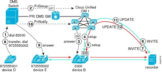
In this use case, the following entities participate:
-
The customer call originates from DN9725550001 deviceD that connects to a DMS switch.
-
The agent receives the call at DN2000 deviceB in clusterCisco Unified CM1.
-
AgentD transfers the call to DN9725550002 deviceE that connects to a DMS switch.
During an automatic call recording session where the far-end (agent) party that connects through a DMS switch transfers the call to a phone that also connects through a DMS switch, the following steps take place:
-
PartyD (far-end party = customer across DMS switch) calls partyB (near-end party = agent) in local cluster by dialing 82000.
-
The DMS switch sends a PriSetup message to the local cluster (Cisco Unified CM1) through a PRI DMS gateway. The message contains information about partyD.
-
PartyB (near-end party = agent in local cluster) answers the call.
-
Because the agent line appearance is configured for automatic recording, the recording session for the media streams automatically gets triggered. Cisco Unified Communications Manager first makes a recording call to the built-in bridge (BIB) of the partyB (agent) IP phone for the agent voice.
-
Cisco Unified Communications Manager makes the second recording call to the BIB of the partyB (agent) IP phone for the customer voice.
-
The recorder receives and answers the recording call setup messages that are sent from local Cisco Unified Communications Manager for the agent voice through a SIP trunk. The agent IP phone starts to fork the partyB (agent) voice stream to the recorder.
-
The recorder receives and answers the recording call setup messages that are sent from local Cisco Unified Communications Manager for the customer voice through a SIP trunk. The agent IP phone starts to fork the partyD (customer) voice stream to the recorder.
-
PartyD across the DMS gateway initiates a consultation transfer (presses Transfer) and dials DN9725550002 deviceE, which is also across the DMS gateway.
-
PartyE answers the call from partyD.
-
The DMS switch sends a PriNotify message to the local cluster (Cisco Unified CM1) through a PRI DMS gateway. The message contains information about partyE.
-
Because partyB is now connecting to a new far-end party, partyE, local Cisco Unified Communications Manager sends two UPDATE messages to the recorder.
-
The recorder receives and answers the recording call UPDATE message that is sent from local Cisco Unified Communications Manager for the partyB (agent) voice through a SIP trunk. The agent IP phone forks the agent voice stream to the recorder.
-
The recorder receives and answers the recording call UPDATE message that is sent from local Cisco Unified Communications Manager for the partyE (customer) voice. The agent IP phone forks the customer voice stream to the recorder.
Note the following particularities of call processing that apply in this use case:
-
In general, when a far-end party on the PSTN side transfers a call, Cisco Unified Communications Manager does not know about the transferring nor transferred-to parties. If the DMS switch or PBX supports PriNotify, however, Cisco Unified Communications Manager receives the PriNotify message when the far-end party changes and can update the far-end information to the recorder.
Note the header information of the INVITE messages from step6 and step11. The SIP header enhancement feature adds the information in bold text to the INVITE and UPDATE message headers.
Step 6 INVITE Message Header Information
From: <sip:2000@ucm1;x-nearend;x-refci=ci2;x-nearenddevice=deviceB;
x-farendrefci=ci1;x-farenddevice=PriDMSGW;x-farendaddr=9725550001>;tag=fromtag1
Step 11 UPDATE Message Header Information
From: <sip:2000@ucm1;x-nearend;x-refci=ci2;x-nearenddevice=deviceB;
x-farendrefci=ci1;x-farenddevice=PriDMSGW;x-farendaddr=9725550002>;tag=fromtag1
Desktop Pickup of Mobile Phone Call
In this use case for automatic call recording, mobile phone user sends call to desk phone for pickup. The following figure illustrates this use case.
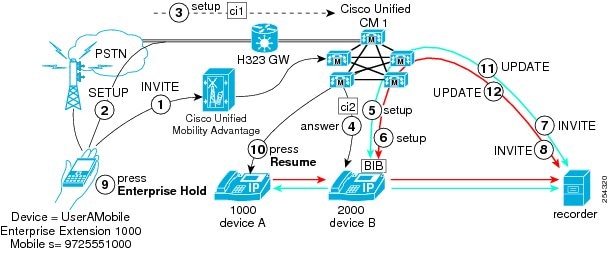
In this use case, the following entities participate:
-
The customer call originates from mobile device UserACell, enterprise extension1000 and mobile number 9725551000.
-
The agent receives the call at DN2000 deviceB.
-
The customer resumes the call from the customer enterprise phone DN1000 deviceA.
During an automatic call recording session where desktop pickup of a mobile phone call occurs, the following steps take place:
-
UserACell calls partyB DN2000 deviceB.
-
Cisco Unified Mobile Communicator client sends SETUP message
-
SETUP message travels through H.323 gateway to local Cisco Unified CM1 cluster.
-
PartyB answers the incoming call from UserACell.
-
Because the agent line appearance is configured for automatic recording, the recording session for the media streams automatically gets triggered. Cisco Unified Communications Manager first makes a recording call to the built-in bridge (BIB) of the partyB (agent) IP phone for the agent voice.
-
Cisco Unified Communications Manager makes the second recording call to the BIB of the partyB (agent) IP phone for the customer voice.
-
The recorder receives and answers the recording INVITE messages that are sent from Cisco Unified Communications Manager for the agent voice through a SIP trunk. The agent IP phone starts to fork the partyB (agent) voice stream to the recorder.
-
The recorder receives and answers the recording INVITE messages that are sent from Cisco Unified Communications Manager for the customer voice through a SIP trunk. The agent IP phone starts to fork the partyUserACell (customer) voice stream to the recorder.
-
UserACell presses Enterprise Hold on the userA mobile phone.
-
UserA presses Resume on the userA desk phone.
-
The recorder receives and answers the recording call UPDATE message that is sent from Cisco Unified Communications Manager for the agent voice through a SIP trunk. The agent IP phone forks the agent voice stream to the recorder.
-
The recorder receives and answers the recording call UPDATE message that is sent from Cisco Unified Communications Manager for the customer voice through a SIP trunk. The agent IP phone forks the customer voice stream to the recorder.
Note the following particularities of call processing that apply in this use case:
-
Mobile phone uses the shared-line concept. When the mobile phone call gets put on hold and the desktop phone resumes the call, the far-end party changes. Cisco Unified Communications Manager sends an update to the recorder.
-
The user picks up the call from the user desk phone to continue the conversation that started on the user mobile phone. To do so, use Cisco Unified Communications Manager to place the call on hold (enterprise hold) through the mobile phone data channel; then, resume the call from the desk phone.
Note the header information of the INVITE messages from step7 and step11. The SIP header enhancement feature adds the information in bold text to the INVITE and UPDATE message headers.
Step 7 INVITE Message Header Information
From: <sip:2000@ucm1;x-nearend;x-refci=ci2;x-nearenddevice=deviceB;
x-farendrefci=ci1;x-farenddevice=UserACell;x-farendaddr=1000>;tag=fromtag1
Step 11 UPDATE Message Header Information
From: <sip:2000@ucm1;x-nearend;x-refci=ci2;x-nearenddevice=deviceB;
x-farendrefci=ci1;x-farenddevice=deviceA;x-farendaddr=1000>;tag=fromtag1
Far-End Party Sends Call to Mobile Phone
In this use case for automatic call recording, the far-end party sends a call to the user mobile phone for mobile phone pickup. (This scenario specifies the opposite of the scenario that the Desktop Pickup of Mobile Phone Call specifies.) The following figure illustrates this use case.
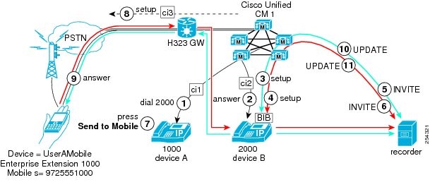
In this use case, the following entities participate:
-
The customer call originates from DN1000 deviceA.
-
The agent receives the call at DN2000 deviceB.
-
The customer resumes the call from the customer mobile phone deviceUserACell enterprise extension1000 mobile number9725551000.
During an automatic call recording session where an enterprise user sends a call to the user mobile phone, the following steps take place:
-
Enterprise user far-end partyA calls partyB DN2000 deviceB from DN1000 deviceA.
-
PartyB DN2000 answers the incoming call from far-end partyA.
-
Because the agent line appearance is configured for automatic recording, the recording session for the media streams automatically gets triggered. Cisco Unified Communications Manager first makes a recording call to the built-in bridge (BIB) of the partyB (agent) IP phone for the agent voice.
-
Cisco Unified Communications Manager makes the second recording call to the BIB of the partyB (agent) IP phone for the customer voice.
-
The recorder receives and answers the recording INVITE messages that are sent from Cisco Unified Communications Manager for the agent voice through a SIP trunk. The agent IP phone starts to fork the partyB (agent) voice stream to the recorder.
-
The recorder receives and answers the recording INVITE messages that are sent from Cisco Unified Communications Manager for the customer voice through a SIP trunk. The agent IP phone starts to fork the partyA (customer) voice stream to the recorder.
-
PartyA presses Send to Mobile on the userA desk phone.
-
Cisco Unified Communications Manager sends a Setup message to the UserA mobile phone.
-
UserA presses answers the ringing call on deviceUserACell.
-
The recorder receives and answers the recording call UPDATE message that is sent from Cisco Unified Communications Manager for the agent voice through a SIP trunk. The agent IP phone forks the agent voice stream to the recorder.
-
The recorder receives and answers the recording call UPDATE message that is sent from Cisco Unified Communications Manager for the customer voice through a SIP trunk. The agent IP phone forks the customer voice stream to the recorder.
Note the following particularities of call processing that apply in this use case:
-
When partyUserACell answers the call, the party USerACell information is sent in a SIP UPDATE message to the recorder.
Note the header information of the INVITE messages from step5 and step10. The SIP header enhancement feature adds the information in bold text to the INVITE and UPDATE message headers.
Step 5 INVITE Message Header Information
From: <sip:2000@ucm1;x-nearend;x-refci=ci2;x-nearenddevice=deviceB;
x-farendrefci=ci1;x-farenddevice=deviceA;x-farendaddr=1000>;tag=fromtag1
Step 10 UPDATE Message Header Information
From: <sip:2000@ucm1;x-nearend;x-refci=ci2;x-nearenddevice=deviceB;
x-farendrefci=ci3;x-farenddevice=UserACell;x-farendaddr=1000>;tag=fromtag1
Far-End Party in Remote Cluster Creates Conference
In this use case for automatic call recording, the far-end party in a remote cluster creates a conference. The following figure illustrates this use case.

In this use case, the following entities participate:
-
The far-end customer call originates from DN3000 deviceD.
-
The near-end agent receives the call at DN2000 deviceB.
-
PartyD creates a conference by conferencing in DN3100 deviceE.
During an automatic call recording session where the far-end party in a remote cluster creates a conference, the following steps take place:
-
PartyD (far-end party = customer in remote cluster) calls partyB (near-end party = agent) by dialing 82000.
-
The INVITE message passes over the SIPTrunkToCluster2 SIP trunk.
-
PartyB (near-end party = agent in local cluster) answers the call.
-
Because the agent line appearance is configured for automatic recording, the recording session for the media streams automatically gets triggered. Cisco Unified Communications Manager first makes a recording call to the built-in bridge (BIB) of the partyB (agent) IP phone for the agent voice.
-
Cisco Unified Communications Manager makes the second recording call to the BIB of the partyB (agent) IP phone for the customer voice.
-
The recorder receives and answers the recording call setup messages that are sent from Cisco Unified Communications Manager for the agent voice through a SIP trunk. The agent IP phone starts to fork the partyB (agent) voice stream to the recorder.
-
The recorder receives and answers the recording call setup messages that are sent from Cisco Unified Communications Manager for the customer voice through a SIP trunk. The agent IP phone starts to fork the partyD (customer) voice stream to the recorder.
-
PartyD initiates a conference by pressing Confn and dialing DN3100.
-
PartyE DN3100 deviceE answers the call.
-
PartyD completes the conference by pressing Confn again.
-
The UPDATE message passes over the SIPTrunkToCluster2 SIP trunk.
-
Because partyB is now connected to a new far-end party, CFB_2, Cisco Unified Communications Manager sends two UPDATE messages to the recorder.
-
The recorder receives and answers the recording call UPDATE message that is sent from Cisco Unified Communications Manager for the partyB (agent) voice through a SIP trunk. The agent IP phone forks the agent voice stream to the recorder.
-
The recorder receives and answers the recording call UPDATE message that is sent from Cisco Unified Communications Manager for CFB_2 (conference bridge) through a SIP trunk. The agent IP phone forks the conference voice stream to the recorder.
Note the following particularities of call processing and configuration that apply in this use case:
-
Cisco Unified Communications Manager has very limited view if a far-end party creates a conference in a remote cluster. The far-end party device is always the trunk that links the two clusters.
-
After the remote conference gets established, the remote Cisco Unified CM2 cluster delivers the b-number (conference bridge identifier) in the SIP UPDATE to the local cluster, Cisco Unified CM1. The Cisco Unified CM1 cluster sends the update to the recorder with the b-number and isfocus indicator.
-
In the figure, the Cisco Unified CM1 cluster gets configured with a SIP trunk, SIPTrunkToCluster2, that links the Cisco Unified CM1 cluster to the Cisco Unified CM2 cluster. The corresponding SIP trunk that is configured in the Cisco Unified CM2 cluster specifies SIPTrunkToCluster1.
-
When the conference gets created by the far-end party with DN3000, the conference bridge identifier, b001234567, does not get passed to cluster Cisco Unified CM1 by default. If the identifier is not passed, the Cisco Unified CM1 cluster can still include the isfocus flag for the far-end party in the From header to the recorder, but the far-end party address will be empty.
-
To allow the conference bridge identifier (the b-number of the conference bridge) to pass from cluster Cisco Unified CM2 to cluster Cisco Unified CM1, the administrator creates a SIP profile in cluster Cisco Unified CM2, checks the Deliver Conference Bridge Identifier check box, and assigns the SIP profile to SIPTrunkToCluster1 in cluster Cisco Unified CM2. The administrator also creates a SIP profile in cluster Cisco Unified CM1 and assigns this SIP profile to the SIPTrunkToCluster2 in cluster Cisco Unified CM1.
-
For more details about configuring SIP profiles, see the Cisco Unified Communications Manager Administration Guide.
Note the header information of the INVITE messages from step6 and step12. The SIP header enhancement feature adds the information in bold text to the INVITE and UPDATE message headers.
Step 6 INVITE Message Header Information
From: <sip:2000@ucm1;x-nearend;x-refci=ci2;x-nearenddevice=deviceB;
x-farendrefci=ci1;x-farenddevice=SIPTrunkToCluster2;x-farendaddr=3000>;tag=fromtag1
Step 12 UPDATE Message Header Information
From: <sip:2000@ucm1;x-nearend;x-refci=ci2;x-nearenddevice=deviceB;
x-farendrefci=ci1;x-farenddevice=SIPTrunkToCluster2;x-farendaddr=b001234567;isfocus>;tag=fromtag1
The UPDATE message in step12 includes isfocus. This isfocus indicates that the near-end party is participating in a conference call. The UPDATE message also includes a b-number as the new far-end address. The b-number specifies the DN of the conference bridge (CFB).
Selective Call Recording
In selective call recording, recording can be initiated using a softkey or programmable line key assigned to the device, a CTI-enabled application, or both interchangeably.
Selective call recording supports two modes:
Silent Recording
In the silent recording mode the call recording status is not reflected on the Cisco IP device display. Silent recording is typically used in a call center environment to enable a supervisor to record an agent call. A CTI-enabled application running on the supervisor desktop is generally used to start and stop the recording for the agent-customer call.
User Recording
In the user recording mode the call recording status is reflected on the Cisco IP device display. A recording may be started or stopped using a softkey, programmable line key, or CTI-enabled application running on the user desktop.
Selective Call Recording Silent Recording mode
In this use case for selective call recording silent recording mode, the supervisor manages the recording session from a CTI-enabled desktop.
The following figure illustrates selective call recording silent recording mode.
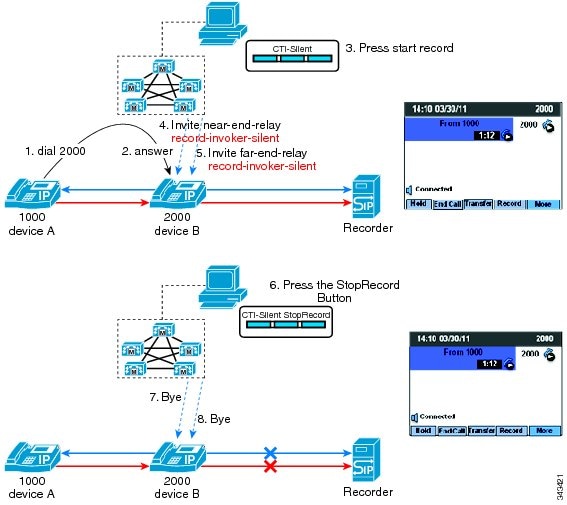
In this use case:
-
Device A (DN 1000) calls device B (DN 2000).
-
The user on device B answers the call.
-
The supervisor uses a CTI-enabled application to start and stop the call recording session.
The supervisor starts the recording session using a CTI-enabled desktop. Cisco Unified Communications Manager makes two recording calls to the built-in bridge (BIB) of the Cisco IP device (one call for the near-end media; another call for the far-end media). The recording calls are automatically and silently answered.
Cisco Unified Communications Manager extends both recording calls to the recording server connected by a SIP trunk.
The recorder receives and answers both recording calls and the user Cisco IP device starts to fork both media streams to the recorder. The call recording status is not reflected on the Cisco IP device display.
The CTI-enabled application is used to stop the recording session. Cisco Unified Communications Manager clears both recording calls.
Selective Call Recording User Recording Mode—Recording Session Managed From a CTI-enabled Application
In this use case for selective call recording user recording mode, the user manages the recording session from a CTI-enabled desktop.
The following figure illustrates selective call recording user recording mode—recording session managed from a CTI-enabled application.

In this use case:
-
Device A (DN 1000) calls device B (DN 2000).
-
The user on device B answers the call.
-
The user on device B uses a CTI-enabled application to start and stop the call recording session.
The user starts the recording session using a CTI-enabled desktop. Cisco Unified Communications Manager makes two recording calls to the built-in bridge (BIB) of the Cisco IP device (one call for the near-end media; another call for the far-end media). The recording calls are automatically and silently answered.
Cisco Unified Communications Manager extends both recording calls to the recording server connected by a SIP trunk.
The recorder receives and answers both recording calls and the user Cisco IP device starts to fork both media streams to the recorder. The Cisco IP device display updates to reflect Recording. The key toggles from Record to StopRec.
The CTI-enabled application is used to stop the recording session. Cisco Unified Communications Manager clears both recording calls.
Selective Call Recording User Recording Mode—Recording Session Managed From a Cisco IP Device
In this use case for selective call recording user recording mode, the user presses a softkey or programmable line key on a Cisco IP device to start and stop the call recording session.
The following figure illustrates selective call recording user recording mode—recording session managed from a Cisco IP device.
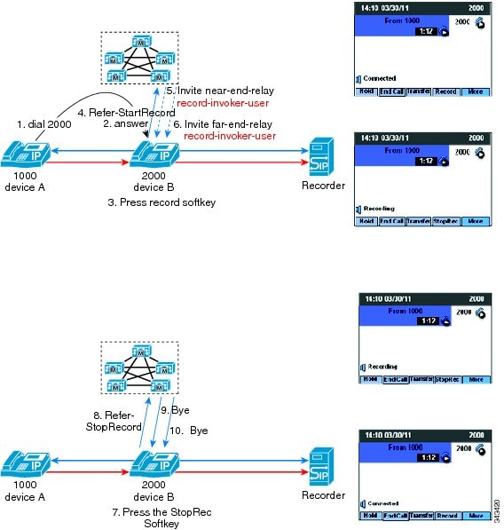
In this use case:
-
Device A (DN 1000) calls device B (DN 2000).
-
The user on device B answers the call.
-
The user on device B uses the softkey or programmable line key on the Cisco IP device to start and stop the call recording session.
The user presses the Record key to start the recording session. Cisco Unified Communications Manager makes two recording calls to the built-in bridge (BIB) of the Cisco IP device (one call for the near-end media; another call for the far-end media). The recording calls are automatically and silently answered.
Cisco Unified Communications Manager extends both recording calls to the recording server connected by a SIP Trunk.
The recorder receives and answers both recording calls and the user Cisco IP device starts to fork both media streams to the recorder. The Cisco IP device display updates to reflect Recording. The key toggles from Record to StopRec.
The User presses the StopRec key to stop the recording session.
Cisco Unified Communications Manager clears both recording calls.
 Feedback