Cisco SIP Proxy Server Integration Guide for Cisco Unity Connection Release 12.x
This document provides instructions for integrating a Cisco SIP Proxy Server phone system with Cisco Unity Connection.
Prerequisites
The Cisco SIP Proxy Server integration supports configurations of the following components:
Phone System
-
A Cisco SIP Proxy Server phone system.
-
Cisco SIP Proxy Server-enabled phones (for example, SIP-enabled Cisco IP Phone 7960 or Pingtel xpressa).
The SIP phones must use the REFER method for call transfers.
-
SIP-enabled gateways (for example, Cisco AS5300 Access Server, Cisco 2600 series router, or Cisco 3600 series router) for access to the PSTN.
For details on compatibility of the phone system components with the integration, see the Compatibility of Phone System Components.
Cisco Unity Connection Server
-
Unity Connection installed and ready for the integration, as described in the Install, Upgrade, and Maintenance Guide for Cisco Unity Connection at https://www.cisco.com/c/en/us/td/docs/voice_ip_comm/connection/12x/install_upgrade/guide/b_12xcuciumg.html.
-
A license that enables the applicable number of voice messaging ports.
Network Configuration
-
Unity Connection server, Cisco SIP Proxy Server, SIP-enabled phones, and SIP-enabled gateways installed on the same subnet (ensures adequate bandwidth and avoids latency issues affecting integration behavior).
Integration Tasks
Before doing the following tasks to integrate Cisco Unity Connection with a Cisco SIP Proxy Server phone system, confirm that Unity Connection is ready for the integration by completing the applicable tasks in the "Installing Cisco Unity Connection” chapter of the Install, Upgrade, and Maintenance Guide for Cisco Unity Connection, Release 12.x, available at https://www.cisco.com/c/en/us/td/docs/voice_ip_comm/connection/12x/install_upgrade/guide/b_12xcuciumg.html.
The following task list describes the process for creating the integration.
Task List to Create the Integration
Use the following task list to integrate Unity Connection with the Cisco SIP Proxy Server phone system.
-
Review the system and equipment requirements to confirm that all phone system and Unity Connection server requirements have been met. See the “Prerequisites” section on page 1.
-
Plan how the voice messaging ports are used by Unity Connection. See the “Planning the Usage of Voice Messaging Ports” section on page 4.
-
Program the Cisco SIP Proxy Server phone system. See the “Programming the Cisco SIP Proxy Server Phone System” section on page 7.
-
Set up the SIP gateway that services Unity Connection. See the “Configure SIP Gateway Servicing Unity Connection” section on page 7.
-
Create the integration. See the “Creating a New Integration with the Cisco SIP Proxy Server Phone System” section on page 8.
-
Test the integration. See the “Testing the Integration” section on page 11.
-
If this integration is a second or subsequent integration, add the applicable new user templates for the new phone system. See the “Adding New User Templates for Multiple Integrations” section on page 15.

Note
While integrating the Cisco Unity Connection with Cisco Unified Call Manager through a SIP Proxy Server uncheck the Synchronize guest time to host option for Unified Communications product line in Virtualized environment. This enables the Unified Communications to synchronize with their clock to external NTP servers.
Integration Description
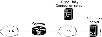
The Cisco SIP Proxy Server integration uses the SIP proxy server to set up communications between the voice messaging ports on the Unity Connection server and the applicable end point (for example, a SIP-enabled phone). The communications occur through:
-
An IP network (LAN, WAN, or Internet) to all SIP-enabled devices connected to it.
-
A SIP-enabled gateway to the PSTN and all phones connected to it.
Figure 1 shows the connections.
Call Information
The proxy server integration sends the following information in the SIP message with calls forwarded:
-
In the Diversion header, the extension of the called party
-
In the Diversion header, the reason for the forward (the extension is busy, does not answer, or is set to forward all calls)
-
In the From header, the extension of the calling party (for internal calls) or the SIP URL of the calling party (if it is an external call and the system uses caller ID)
Unity Connection uses this information to answer the call appropriately. For example, a call forwarded to Unity Connection is answered with the personal greeting of the user. If the phone system routes the call to Unity Connection without this information, Unity Connection answers with the opening greeting.
Integration Functionality
The Cisco SIP Proxy Server integration with Unity Connection provides the following features:
-
Call forward to personal greeting
-
Call forward to busy greeting
-
Caller ID
-
Easy message access (a user can retrieve messages without entering an ID; Cisco Unity Connection identifies a user based on the extension from which the call originated; a password may be required)
-
Identified user messaging (Cisco Unity Connection identifies a user who leaves a message during a forwarded internal call, based on the extension from which the call originated)
-
Message waiting indication (MWI)
Integrations with Multiple Phone Systems
When Unity Connection is installed as Cisco Business Edition—on the same server with Cisco Unified Communications Manager—Unity Connection cannot be integrated with multiple phone systems at one time.
When Unity Connection is not installed as Cisco Business Edition, Unity Connection can be integrated with multiple phone systems at one time. For information on and instructions for integrating Unity Connection with multiple phone systems, see the Multiple Phone System Integration Guide for Cisco Unity Connection Release 12.x at https://www.cisco.com/c/en/us/td/docs/voice_ip_comm/connection/12x/integration/guide/multiple_integration/b_cuc12xintmultiple.html.
Planning the Usage of Voice Messaging Ports
Before programming the phone system, you need to plan how the voice messaging ports are used by Unity Connection.
Unlike other integrations, the hunt group mechanism for a Cisco SIP Proxy Server integration is implemented on the Unity Connection server. Within a port group, each incoming call hunts for an available voice messaging port among all the ports in a round-robin (or circular) fashion. If a voice messaging port in the port group is set not to answer calls or is not enabled, a call reaching that port may receive a busy signal.
The following considerations affect the programming for the phone system (for example, setting up the hunt group or call forwarding for the voice messaging ports):
-
The number of voice messaging ports installed.
For a Unity Connection cluster, each Unity Connection server must have enough ports to handle all voice messaging traffic in case the other server stops functioning. -
The number of voice messaging ports that answer calls.
-
The number of voice messaging ports that only dial out, for example, to send message notification, to set message waiting indicators (MWIs), and to make telephone record and playback (TRAP) connections.
The following table describes the voice messaging port settings in Unity Connection that can be set on Telephony Integrations > Port of Cisco Unity Connection Administration.
|
Field |
Considerations |
||
|---|---|---|---|
|
Enabled |
Check this check box. |
||
|
Server |
(When a Unity Connection cluster is configured) Select the name of the Unity Connection server that you want to handle this port. Assign an equal number of answering and dial-out voice messaging ports to the Unity Connection servers so that they equally share the voice messaging traffic. |
||
|
Answer Calls |
Check this check box.
|
||
|
Perform Message Notification |
Check this check box to designate the port for notifying users of messages. |
||
|
Send MWI Requests |
Check this check box to designate the port for turning MWIs on and off. |
||
|
Allow TRAP Connections |
Check this check box so that users can use the phone as a recording and playback device in Cisco Unity Connection web applications. |
Voice Messaging Ports to Install
The number of voice messaging ports to install depends on numerous factors, including:
-
The number of calls Unity Connection answer when call traffic is at its peak.
-
The expected length of each message that callers record and that users listen to.
-
The number of users.
-
The number of calls made for message notification.
-
The number of MWIs that are activated when call traffic is at its peak.
-
The number of TRAP connections needed when call traffic is at its peak. (TRAP connections are used by Cisco Unity Connection web applications to play back and record over the phone.)
-
The number of calls that use the automated attendant and call handlers when call traffic is at its peak.
-
Whether a Cisco Unity Connection cluster is configured. For considerations, see the “Considerations for a Unity Connection Cluster” section on page 6.
It is best to install only the number of voice messaging ports that are needed so that system resources are not allocated to unused ports.
Voice Messaging Ports that Answer Calls
The calls that the voice messaging ports answer can be incoming calls from unidentified callers or from users. Assign all of the voice messaging ports to answer calls.
You can set voice messaging ports to both answer calls and to dial out (for example, to send message notifications).
If your system is configured for a Cisco Unity Connection cluster, see the “Considerations for a Unity Connection Cluster” section on page 6.
Voice Messaging Ports that Dial Out
Ports that only dial out can do one or more of the following:
-
Notify users by phone, pager, or email of messages that have arrived.
-
Turn MWIs on and off for user extensions.
-
Make a TRAP Unity Connection so that users can use the phone as a recording and playback device in Cisco Unity Connection web applications.
If your system is configured for a Cisco Unity Connection cluster, see the “Considerations for a Unity Connection Cluster” section on page 6.
Considerations for a Unity Connection Cluster
If your system is configured for a Unity Connection cluster, consider how the voice messaging ports are used in different scenarios.
When Both Unity Connection Servers are Functioning Normally
-
A hunt group is configured on the phone system to distribute calls equally to both Unity Connection servers.
-
The network is configured to send incoming calls first to the subscriber server, then to the publisher server if no answering ports are available on the subscriber server.
-
Both Unity Connection servers are active and handle voice messaging traffic for the system.
-
In Cisco Unity Connection Administration, the voice messaging ports are configured so that an equal number of voice messaging ports are assigned to each Unity Connection server. This guide directs you to assign the voice messaging ports to their specific server at the applicable time.
-
The number of voice messaging ports that are assigned to one Unity Connection server must be sufficient to handle all of the voice messaging traffic for the system (answering calls and dialing out) when the other Unity Connection server stops functioning.
If both Unity Connection servers must be functioning to handle the voice messaging traffic, the system do not have sufficient capacity when one of the servers stops functioning. -
Each Unity Connection server is assigned half the total number of voice messaging ports.
If all the voice messaging ports are assigned to one Unity Connection server, the other Unity Connection server is not able to answer calls or to dial out. -
Each Unity Connection server must have voice messaging ports that answer calls and that can dial out (for example, to set MWIs).
When Only One Unity Connection Server is Functioning
-
The hunt group on the phone system sends all calls to the functioning Unity Connection server.
-
The functioning Unity Connection server receives all voice messaging traffic for the system.
-
The number of voice messaging ports that are assigned to the functioning Unity Connection server must be sufficient to handle all of the voice messaging traffic for the system (answering calls and dialing out).
-
The functioning Unity Connection server must have voice messaging ports that answer calls and that can dial out (for example, to set MWIs).
If the functioning Unity Connection server does not have voice messaging ports for answering calls, the system is not able to answer incoming calls. Similarly, if the functioning Unity Connection server does not have voice messaging ports for dialing out, the system will not be able to dial out (for example, to set MWIs).
Programming the Cisco SIP Proxy Server Phone System
If you use programming options other than those supplied in the following procedure, the performance of the integration may be affected. Do the following procedure to program the Cisco SIP Proxy Server Phone System.
SUMMARY STEPS
- Install and set up the Cisco SIP Proxy Server as described in the server documentation: Task List to Create the Integration
- For a Cisco Unity Connection cluster, identify the Unity Connection servers with a fully qualified domain name (FQDN), and configure a DNS server to resolve the FQDN to the IP addresses and SIP ports of the Cisco Unity Connection server.
- Program each phone to forward calls to <the contact line name>@<SIP proxy server>, the voice messaging line name that users will use to contact Unity Connection.
- If Unity Connection will authenticate with the Cisco SIP Proxy Server, enter a user record for the contact line name that Unity Connection will use.
DETAILED STEPS
| Step 1 |
Install and set up the Cisco SIP Proxy Server as described in the server documentation: Task List to Create the Integration |
| Step 2 |
For a Cisco Unity Connection cluster, identify the Unity Connection servers with a fully qualified domain name (FQDN), and configure a DNS server to resolve the FQDN to the IP addresses and SIP ports of the Cisco Unity Connection server. |
| Step 3 |
Program each phone to forward calls to <the contact line name>@<SIP proxy server>, the voice messaging line name that users will use to contact Unity Connection. |
| Step 4 |
If Unity Connection will authenticate with the Cisco SIP Proxy Server, enter a user record for the contact line name that Unity Connection will use. |
Configure SIP Gateway Servicing Unity Connection
To configure the SIP gateway for the SIP integration with Cisco Unity Connection, do the following three procedures.
Configuring Application Session on the SIP Gateway
SUMMARY STEPS
- On the VoIP dial-peer servicing Unity Connection, use the following command:
- Create a destination pattern that matches the voice messaging port numbers. For example, if the system has voice messaging ports 1001 through 1016, enter the dial-peer destination pattern 10xx.
- Repeat Step 1 and Step 2 for all remaining VoIP dial-peers servicing Cisco Unity Connection.
DETAILED STEPS
| Step 1 |
On the VoIP dial-peer servicing Unity Connection, use the following command: |
| Step 2 |
Create a destination pattern that matches the voice messaging port numbers. For example, if the system has voice messaging ports 1001 through 1016, enter the dial-peer destination pattern 10xx. |
| Step 3 |
Repeat Step 1 and Step 2 for all remaining VoIP dial-peers servicing Cisco Unity Connection. |
Disabling the SIP Media Inactivity Timer
Procedure
| Step 1 |
On the gateway, go into the gateway configuration mode by entering the following command: |
| Step 2 |
Disable the RTCP timer by entering the following command: |
| Step 3 |
Exit the gateway configuration mode by entering the following command: |
Enabling DTMF Relay for SIP Calls by Using Named Telephony Events
Procedure
| Step 1 |
On the gateway, go into dial-peer configuration mode and define the VoIP dial peer by entering the following command: |
| Step 2 |
Configure the SIP protocol on the gateway by entering the following command: |
| Step 3 |
Enable DTMF relay using NTE RTP packets by entering the following command: |
| Step 4 |
Configure the type of payload in the NTE packet by entering the following command: |
Creating a New Integration with the Cisco SIP Proxy Server Phone System
After ensuring that Cisco SIP Proxy Server phone system and Cisco Unity Connection are ready for the integration, do the following procedure to set up the integration and to enter the port settings.
SUMMARY STEPS
- In Cisco Unity Connection Administration, expand Telephony Integrations, then select Phone System.
- On the Search Phone Systems page, under Display Name, select the name of the default phone system.
- On the Phone System Basics page, in the Phone System Name field, enter the descriptive name that you want for the phone system.
- If you want to use this phone system as the default for TRaP connections so that administrators and users without voicemail boxes can record and playback through the phone in Unity Connection web applications, check the Default TRAP Switch check box. If you want to use another phone system as the default for TRaP connections, uncheck this check box.
- Select Save.
- On the Phone System Basics page, in the Related Links drop-down box, select Add Port Group and select Go.
- On the New Port Group page, enter the applicable settings and select Save.
- On the Port Group Basics page, do the following substeps if there is a secondary Cisco SIP Proxy Server. Otherwise, continue to Step 9.
- On the Port Group Basics page, in the Related Links drop-down box, select Add Ports and select Go.
- On the New Port page, enter the following settings and select Save.
- On the Search Ports page, select the display name of the first voice messaging port that you created for this phone system integration.
- On the Port Basics page, set the voice messaging port settings as applicable. The fields in the following table are the ones that you can change.
- Select Save.
- Select Next.
- Repeat Step 12 through Step 14 for all remaining voice messaging ports for the phone system.
- If another phone system integration exists, in Cisco Unity Connection Administration, expand Telephony Integrations, then select Trunk. Otherwise, skip to Step 20.
- On the Search Phone System Trunks page, on the Phone System Trunk menu, select New Phone System Trunk.
- On the New Phone System Trunk page, enter the following settings for the phone system trunk and select Save.
- Repeat Step 17 and Step 18 for all remaining phone system trunks that you want to create.
- In the Related Links drop-down list, select Check Telephony Configuration and select Go to confirm the phone system integration settings.
- In the Task Execution Results window, select Close.
DETAILED STEPS
| Step 1 |
In Cisco Unity Connection Administration, expand Telephony Integrations, then select Phone System. |
||||||||||||||||||||||||||
| Step 2 |
On the Search Phone Systems page, under Display Name, select the name of the default phone system. |
||||||||||||||||||||||||||
| Step 3 |
On the Phone System Basics page, in the Phone System Name field, enter the descriptive name that you want for the phone system. |
||||||||||||||||||||||||||
| Step 4 |
If you want to use this phone system as the default for TRaP connections so that administrators and users without voicemail boxes can record and playback through the phone in Unity Connection web applications, check the Default TRAP Switch check box. If you want to use another phone system as the default for TRaP connections, uncheck this check box. |
||||||||||||||||||||||||||
| Step 5 |
Select Save. |
||||||||||||||||||||||||||
| Step 6 |
On the Phone System Basics page, in the Related Links drop-down box, select Add Port Group and select Go. |
||||||||||||||||||||||||||
| Step 7 |
On the New Port Group page, enter the applicable settings and select Save.
|
||||||||||||||||||||||||||
| Step 8 |
On the Port Group Basics page, do the following substeps if there is a secondary Cisco SIP Proxy Server. Otherwise, continue to Step 9. |
||||||||||||||||||||||||||
| Step 9 |
On the Port Group Basics page, in the Related Links drop-down box, select Add Ports and select Go. |
||||||||||||||||||||||||||
| Step 10 |
On the New Port page, enter the following settings and select Save.
|
||||||||||||||||||||||||||
| Step 11 |
On the Search Ports page, select the display name of the first voice messaging port that you created for this phone system integration.
|
||||||||||||||||||||||||||
| Step 12 |
On the Port Basics page, set the voice messaging port settings as applicable. The fields in the following table are the ones that you can change.
|
||||||||||||||||||||||||||
| Step 13 |
Select Save. |
||||||||||||||||||||||||||
| Step 14 |
Select Next. |
||||||||||||||||||||||||||
| Step 15 |
Repeat Step 12 through Step 14 for all remaining voice messaging ports for the phone system. |
||||||||||||||||||||||||||
| Step 16 |
If another phone system integration exists, in Cisco Unity Connection Administration, expand Telephony Integrations, then select Trunk. Otherwise, skip to Step 20. |
||||||||||||||||||||||||||
| Step 17 |
On the Search Phone System Trunks page, on the Phone System Trunk menu, select New Phone System Trunk. |
||||||||||||||||||||||||||
| Step 18 |
On the New Phone System Trunk page, enter the following settings for the phone system trunk and select Save.
|
||||||||||||||||||||||||||
| Step 19 |
Repeat Step 17 and Step 18 for all remaining phone system trunks that you want to create. |
||||||||||||||||||||||||||
| Step 20 |
In the Related Links drop-down list, select Check Telephony Configuration and select Go to confirm the phone system integration settings. If the test is not successful, the Task Execution Results displays one or more messages with troubleshooting steps. After correcting the problems, test the Unity Connection again. |
||||||||||||||||||||||||||
| Step 21 |
In the Task Execution Results window, select Close. |
Testing the Integration
To test whether Cisco Unity Connection and the phone system are integrated correctly, do the following procedures in the order listed.
If any of the steps indicate a failure, see the following documentation as applicable:
-
The installation guide for the phone system.
-
Troubleshooting Guide for Cisco Unity Connection Release 12.x, available at https://www.cisco.com/c/en/us/td/docs/voice_ip_comm/connection/12x/troubleshooting/guide/b_12xcuctsg.html
-
The setup information earlier in this guide.
Setting Up the Test Configuration
SUMMARY STEPS
- Set up two test extensions (Phone 1 and Phone 2) on the same phone system that Unity Connection is connected to.
- Set Phone 1 to forward calls to the Unity Connection pilot number when calls are not answered.
- To create a test user for testing, in Cisco Unity Connection Administration, expand Users, then select Users.
- On the Search Users page, select the display name of a user to use for testing. The extension for this user must be the extension for Phone 1.
- On the Edit User Basics page, uncheck the Set for Self-enrollment at Next Login check box.
- In the Voice Name field, record a recorded name for the test user.
- Select Save.
- On the Edit menu, select Message Waiting Indicators.
- On the Message Waiting Indicators page, select the message waiting indicator. If no message waiting indication is in the table, select Add New.
- On the Edit Message Waiting Indicator page, enter the following settings.
- Select Save.
- On the Edit menu, select Transfer Rules.
- On the Transfer Rules page, select the active option.
- On the Edit Transfer Rule page, under Transfer Action, select the Extension option and enter the extension of Phone 1.
- In the Transfer Type field, select Release to Switch.
- Select Save.
- Minimize the Cisco Unity Connection Administration window.
- Sign in to the Real-Time Monitoring Tool (RTMT).
- On the Unity Connection menu, select Port Monitor. The Port Monitor tool appears in the right pane.
- In the right pane, select Start Polling. The Port Monitor will display which port is handling the calls that you will make.
DETAILED STEPS
| Step 1 |
Set up two test extensions (Phone 1 and Phone 2) on the same phone system that Unity Connection is connected to. |
||||||||
| Step 2 |
Set Phone 1 to forward calls to the Unity Connection pilot number when calls are not answered.
|
||||||||
| Step 3 |
To create a test user for testing, in Cisco Unity Connection Administration, expand Users, then select Users. |
||||||||
| Step 4 |
On the Search Users page, select the display name of a user to use for testing. The extension for this user must be the extension for Phone 1. |
||||||||
| Step 5 |
On the Edit User Basics page, uncheck the Set for Self-enrollment at Next Login check box. |
||||||||
| Step 6 |
In the Voice Name field, record a recorded name for the test user. |
||||||||
| Step 7 |
Select Save. |
||||||||
| Step 8 |
On the Edit menu, select Message Waiting Indicators. |
||||||||
| Step 9 |
On the Message Waiting Indicators page, select the message waiting indicator. If no message waiting indication is in the table, select Add New. |
||||||||
| Step 10 |
On the Edit Message Waiting Indicator page, enter the following settings.
|
||||||||
| Step 11 |
Select Save. |
||||||||
| Step 12 |
On the Edit menu, select Transfer Rules. |
||||||||
| Step 13 |
On the Transfer Rules page, select the active option. |
||||||||
| Step 14 |
On the Edit Transfer Rule page, under Transfer Action, select the Extension option and enter the extension of Phone 1. |
||||||||
| Step 15 |
In the Transfer Type field, select Release to Switch. |
||||||||
| Step 16 |
Select Save. |
||||||||
| Step 17 |
Minimize the Cisco Unity Connection Administration window. Do not close the Cisco Unity Connection Administration window because you will use it again in a later procedure. |
||||||||
| Step 18 |
Sign in to the Real-Time Monitoring Tool (RTMT). |
||||||||
| Step 19 |
On the Unity Connection menu, select Port Monitor. The Port Monitor tool appears in the right pane. |
||||||||
| Step 20 |
In the right pane, select Start Polling. The Port Monitor will display which port is handling the calls that you will make. |
Testing an External Call with Release Transfer
SUMMARY STEPS
- From Phone 2, enter the access code necessary to get an outside line, then enter the number outside callers use to dial directly to Unity Connection.
- In the Port Monitor, note which port handles this call.
- When you hear the opening greeting, enter the extension for Phone 1. Hearing the opening greeting means that the port is configured correctly.
- Confirm that Phone 1 rings and that you hear a ringback tone on Phone 2. Hearing a ringback tone means that Unity Connection correctly released the call and transferred it to Phone 1.
- Leaving Phone 1 unanswered, confirm that the state of the port handling the call changes to “Idle.” This state means that release transfer is successful.
- Confirm that, after the number of rings that the phone system is set to wait, the call is forwarded to Unity Connection and that you hear the greeting for the test user. Hearing the greeting means that the phone system forwarded the unanswered call and the call-forward information to Unity Connection, which correctly interpreted the information.
- On the Port Monitor, note which port handles this call.
- Leave a message for the test user and hang up Phone 2.
- In the Port Monitor, confirm that the state of the port handling the call changes to “Idle.” This state means that the port was successfully released when the call ended.
- Confirm that the MWI on Phone 1 is activated. The activated MWI means that the phone system and Cisco Unity Connection are successfully integrated for turning on MWIs.
DETAILED STEPS
| Step 1 |
From Phone 2, enter the access code necessary to get an outside line, then enter the number outside callers use to dial directly to Unity Connection. |
| Step 2 |
In the Port Monitor, note which port handles this call. |
| Step 3 |
When you hear the opening greeting, enter the extension for Phone 1. Hearing the opening greeting means that the port is configured correctly. |
| Step 4 |
Confirm that Phone 1 rings and that you hear a ringback tone on Phone 2. Hearing a ringback tone means that Unity Connection correctly released the call and transferred it to Phone 1. |
| Step 5 |
Leaving Phone 1 unanswered, confirm that the state of the port handling the call changes to “Idle.” This state means that release transfer is successful. |
| Step 6 |
Confirm that, after the number of rings that the phone system is set to wait, the call is forwarded to Unity Connection and that you hear the greeting for the test user. Hearing the greeting means that the phone system forwarded the unanswered call and the call-forward information to Unity Connection, which correctly interpreted the information. |
| Step 7 |
On the Port Monitor, note which port handles this call. |
| Step 8 |
Leave a message for the test user and hang up Phone 2. |
| Step 9 |
In the Port Monitor, confirm that the state of the port handling the call changes to “Idle.” This state means that the port was successfully released when the call ended. |
| Step 10 |
Confirm that the MWI on Phone 1 is activated. The activated MWI means that the phone system and Cisco Unity Connection are successfully integrated for turning on MWIs. |
Testing Listening to Messages
SUMMARY STEPS
- From Phone 1, enter the internal pilot number for Unity Connection.
- When asked for your password, enter the password for the test user. Hearing the request for your password means that the phone system sent the necessary call information to Cisco Unity Connection, which correctly interpreted the information.
- Confirm that you hear the recorded name for the test user (if you did not record a name for the test user, you will hear the extension number for Phone 1). Hearing the recorded name means that Cisco Unity Connection correctly identified the user by the extension.
- Listen to the message.
- After listening to the message, delete the message.
- Confirm that the MWI on Phone 1 is deactivated. The deactivated MWI means that the phone system and Unity Connection are successfully integrated for turning off MWIs.
- Hang up Phone 1.
- On the Port Monitor, confirm that the state of the port handling the call changes to “Idle.” This state means that the port was successfully released when the call ended.
DETAILED STEPS
| Step 1 |
From Phone 1, enter the internal pilot number for Unity Connection. |
| Step 2 |
When asked for your password, enter the password for the test user. Hearing the request for your password means that the phone system sent the necessary call information to Cisco Unity Connection, which correctly interpreted the information. |
| Step 3 |
Confirm that you hear the recorded name for the test user (if you did not record a name for the test user, you will hear the extension number for Phone 1). Hearing the recorded name means that Cisco Unity Connection correctly identified the user by the extension. |
| Step 4 |
Listen to the message. |
| Step 5 |
After listening to the message, delete the message. |
| Step 6 |
Confirm that the MWI on Phone 1 is deactivated. The deactivated MWI means that the phone system and Unity Connection are successfully integrated for turning off MWIs. |
| Step 7 |
Hang up Phone 1. |
| Step 8 |
On the Port Monitor, confirm that the state of the port handling the call changes to “Idle.” This state means that the port was successfully released when the call ended. |
Setting Up Supervised Transfer on Unity Connection
SUMMARY STEPS
- In Cisco Unity Connection Administration, on the Edit Transfer Rule page for the test user, in the Transfer Type field, select Supervise Transfer.
- In the Rings to Wait For field, enter 3.
- Select Save.
- Minimize the Cisco Unity Connection Administration window.
DETAILED STEPS
| Step 1 |
In Cisco Unity Connection Administration, on the Edit Transfer Rule page for the test user, in the Transfer Type field, select Supervise Transfer. |
| Step 2 |
In the Rings to Wait For field, enter 3. |
| Step 3 |
Select Save. |
| Step 4 |
Minimize the Cisco Unity Connection Administration window. Do not close the Cisco Unity Connection Administration window because you will use it again in a later procedure. |
Testing Supervised Transfer
SUMMARY STEPS
- From Phone 2, enter the access code necessary to get an outside line, then enter the number outside callers use to dial directly to Unity Connection.
- On the Port Monitor, note which port handles this call.
- When you hear the opening greeting, enter the extension for Phone 1. Hearing the opening greeting means that the port is configured correctly.
- Confirm that Phone 1 rings and that you do not hear a ringback tone on Phone 2. Instead, you should hear the indication your phone system uses to mean that the call is on hold (for example, music).
- Leaving Phone 1 unanswered, confirm that the state of the port handling the call remains “Busy.” This state and hearing an indication that you are on hold mean that Unity Connection is supervising the transfer.
- Confirm that, after three rings, you hear the greeting for the test user. Hearing the greeting means that Unity Connection successfully recalled the supervised-transfer call.
- During the greeting, hang up Phone 2.
- On the Port Monitor, confirm that the state of the port handling the call changes to “Idle.” This state means that the port was successfully released when the call ended.
- Select Stop Polling.
- Sign out of RTMT.
DETAILED STEPS
| Step 1 |
From Phone 2, enter the access code necessary to get an outside line, then enter the number outside callers use to dial directly to Unity Connection. |
| Step 2 |
On the Port Monitor, note which port handles this call. |
| Step 3 |
When you hear the opening greeting, enter the extension for Phone 1. Hearing the opening greeting means that the port is configured correctly. |
| Step 4 |
Confirm that Phone 1 rings and that you do not hear a ringback tone on Phone 2. Instead, you should hear the indication your phone system uses to mean that the call is on hold (for example, music). |
| Step 5 |
Leaving Phone 1 unanswered, confirm that the state of the port handling the call remains “Busy.” This state and hearing an indication that you are on hold mean that Unity Connection is supervising the transfer. |
| Step 6 |
Confirm that, after three rings, you hear the greeting for the test user. Hearing the greeting means that Unity Connection successfully recalled the supervised-transfer call. |
| Step 7 |
During the greeting, hang up Phone 2. |
| Step 8 |
On the Port Monitor, confirm that the state of the port handling the call changes to “Idle.” This state means that the port was successfully released when the call ended. |
| Step 9 |
Select Stop Polling. |
| Step 10 |
Sign out of RTMT. |
Adding New User Templates for Multiple Integrations
When you create the first phone system integration, this phone system is automatically selected in the default user template. The users that you add after creating this phone system integration will be assigned to this phone system by default.
However, for each additional phone system integration that you create, you must add the applicable new user templates that will assign users to the new phone system. You must add the new templates before you add new users who will be assigned to the new phone system.
For details on adding new user templates, or on selecting a user template when adding a new user, see the “User Templates” section in “User Attributes” chapter of the System Administration Guide for Cisco Unity Connection Release 12.x. The guide is available at
Compatibility of Phone System Components
Testing has shown compatibility of the following phone system components with Cisco Unity Connection in a SIP integration.
|
Version |
Comments |
|---|---|
|
1.3 |
If Cisco Unity Connection authenticates with the SIP proxy server, the authentication name entered in Cisco Unity Connection must be the same as the contact line name in the SIP proxy server. |
|
2.0 |
If Cisco Unity Connection authenticates with the SIP proxy server, the authentication name entered in Cisco Unity Connection must be the same as the contact line name in the SIP proxy server. |
|
Version |
Comments |
|---|---|
|
7960 P0S3-03-1-00 |
|
|
7960 P0S3-03-2-00 |
|
|
7960 P0S3-04-0-00 |
When the phone initiates a call, release transfer of the call is not available to Cisco Unity Connection. |
|
7960 P0S3-04-1-00 |
When the phone initiates a call, release transfer of the call is not available to Cisco Unity Connection. |
|
7960 P0S3-04-2-00 |
|
Version |
Comments |
|---|---|
|
1.2.6 |
To get the call forwarding to busy greeting integration feature, forwarding must be programmed on the SIP proxy server rather than configured on the Pingtel xpressa phones. |
|
2.0.1 2.0.2 |
Not compatible. Silence is inserted into the audio stream every few seconds. To get the call forwarding to busy greeting integration feature, forwarding must be programmed on the SIP proxy server rather than configured on the Pingtel xpressa phones. |
|
Version |
Comments |
|---|---|
|
12.2(2)XB4 |
|
|
12.2(2)XB6 |
Other compatibility issues are:
-
The Pingtel xpressa cannot connect to a backup SIP proxy server.
-
To enable call forwarding when Cisco Unity Connection is configured for failover, set the forwarding destinations in MySQL to be <contact line name>@proxy instead of <contact line name>@Unity Connection.
 Feedback