Failover Configuration Guide for Cisco Digital Media Suite 5.4.x
Bias-Free Language
The documentation set for this product strives to use bias-free language. For the purposes of this documentation set, bias-free is defined as language that does not imply discrimination based on age, disability, gender, racial identity, ethnic identity, sexual orientation, socioeconomic status, and intersectionality. Exceptions may be present in the documentation due to language that is hardcoded in the user interfaces of the product software, language used based on RFP documentation, or language that is used by a referenced third-party product. Learn more about how Cisco is using Inclusive Language.
Chapter: About Failover
About Failover
This chapter describes how to configure two Cisco DMS appliances so that one will take over operation if the other one fails.
This chapter includes these sections.
•![]() Important Notes for Failover Configuration
Important Notes for Failover Configuration
Overview
You can configure Cisco DMS appliances in a stateless, active/standby failover configuration. The failover configuration requires two identical Cisco DMS appliances connected to each other through a dedicated failover link. The health of the active unit is monitored to determine if specific failover conditions are met. When these conditions are met, failover occurs.
This section contains these topics.
•![]() Cisco DMS Failover Terminology
Cisco DMS Failover Terminology
•![]() Supported Failover Configurations
Supported Failover Configurations
Cisco DMS Failover Terminology
The following terms are used throughout this document to describe failover configurations.
•![]() Active appliance—The appliance that is currently responding to user requests. Always access the active appliances using the virtual IP address and virtual FQDN.
Active appliance—The appliance that is currently responding to user requests. Always access the active appliances using the virtual IP address and virtual FQDN.
•![]() Application interface—the interface on a Cisco DMM appliance that users connect to. Health monitoring also occurs through this interface.
Application interface—the interface on a Cisco DMM appliance that users connect to. Health monitoring also occurs through this interface.
•![]() Dedicated FQDN—an FQDN that is assigned to the appliance. This FQDN remains with the appliance during a failover. The appliance is reachable through this FQDN, but it should only be used if you are trying to access the AAI interface of the standby appliance (you cannot access the GUI of an appliance in the standby state).
Dedicated FQDN—an FQDN that is assigned to the appliance. This FQDN remains with the appliance during a failover. The appliance is reachable through this FQDN, but it should only be used if you are trying to access the AAI interface of the standby appliance (you cannot access the GUI of an appliance in the standby state).
Users should never use the dedicated FQDN to access Cisco DMM GUI on the active appliance; they should use the Virtual FQDN to access the active appliance GUI.
•![]() Dedicated IP address—an IP address that is assigned to the appliance. This IP address remains with the appliance during a failover.
Dedicated IP address—an IP address that is assigned to the appliance. This IP address remains with the appliance during a failover.
•![]() Primary appliance—the appliance in a failover pair that is initially put into the active state and is the source of data during the initial configuration. When adding failover to an existing Cisco DMS installation, the existing Cisco DMS appliances are the primary appliances. The virtual IP address and virtual FQDN are obtained from the primary appliances.
Primary appliance—the appliance in a failover pair that is initially put into the active state and is the source of data during the initial configuration. When adding failover to an existing Cisco DMS installation, the existing Cisco DMS appliances are the primary appliances. The virtual IP address and virtual FQDN are obtained from the primary appliances.
•![]() Replication interface—the interface that connects two appliances in a failover pair together. Health monitoring and data replication happen through this interface. You cannot access the Cisco DMM GUI through the replication interface.
Replication interface—the interface that connects two appliances in a failover pair together. Health monitoring and data replication happen through this interface. You cannot access the Cisco DMM GUI through the replication interface.
•![]() Secondary appliance—the appliance that is initially put into the standby state. When adding failover to an existing Cisco DMS installation, the secondary appliances are the ones you add to the existing configuration.
Secondary appliance—the appliance that is initially put into the standby state. When adding failover to an existing Cisco DMS installation, the secondary appliances are the ones you add to the existing configuration.
•![]() Standby appliance—The appliance that is not actively responding to user requests. The standby appliance monitors the active appliance health for failover triggers. During a failover, the standby appliance becomes active and takes over the virtual IP address and FQDN.
Standby appliance—The appliance that is not actively responding to user requests. The standby appliance monitors the active appliance health for failover triggers. During a failover, the standby appliance becomes active and takes over the virtual IP address and FQDN.
•![]() Virtual FQDN—the FQDN used by the active appliance, no matter which physical appliance is the active appliance. Users and administrators should always use the virtual FQDN to access the Cisco DMM appliance interface.
Virtual FQDN—the FQDN used by the active appliance, no matter which physical appliance is the active appliance. Users and administrators should always use the virtual FQDN to access the Cisco DMM appliance interface.
•![]() Virtual IP address—the IP address used by the active appliance, no matter which physical appliance is the active appliance. If the active appliance fails, the virtual IP address is used by the standby appliance as it becomes active.
Virtual IP address—the IP address used by the active appliance, no matter which physical appliance is the active appliance. If the active appliance fails, the virtual IP address is used by the standby appliance as it becomes active.
Supported Failover Configurations
Failover is supported for Cisco Digital Signs implementations.
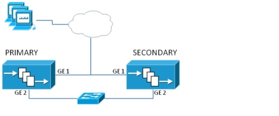
A Cisco Digital Signs implementation requires that the primary Cisco DMM appliance is paired with a secondary Cisco DMM appliance that acts as a standby appliance. The application interfaces (GigabitEthernet 1) of the appliances must be on the same subnet. The two appliances are connected by either a crossover cable (see Figure 1-1) or a switch (Figure 1-2) on their GigabitEthernet 2 interfaces. This connection is used to monitor failover health and replicate data between them.
Figure 1-1 Digital Signs Failover with a Crossover Cable
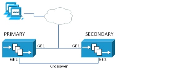
Figure 1-2 Digital Signs Failover with a Switch
For detailed information on how to configure Cisco Digital Signs failover, see Configure Failover for Cisco Digital Signs.
Failover Triggers
The following events trigger failover:
•![]() The standby device fails to receive 10 heartbeat messages from the active device.
The standby device fails to receive 10 heartbeat messages from the active device.
Heartbeat messages are sent once a second. Missing 10 consecutive heartbeats causes a failover.
•![]() Manually restarting the following services using the AAI interface:
Manually restarting the following services using the AAI interface:
–![]() Web services (Tomcat)
Web services (Tomcat)
–![]() Database services
Database services
•![]() Rebooting the active appliance.
Rebooting the active appliance.
•![]() Loss of power (either because you powered the appliance off or there was a general power failure)
Loss of power (either because you powered the appliance off or there was a general power failure)
•![]() Pairing the active appliances.
Pairing the active appliances.
•![]() Restoring a backup on the active appliance.
Restoring a backup on the active appliance.
•![]() Changing the logging level.
Changing the logging level.
•![]() Re-generating a certificate.
Re-generating a certificate.
•![]() Reaching the fail count threshold (5) for a monitored service running on the active appliance. When a service stops, the appliance automatically attempts to restart it. Each time the service fails, a fail counter increments. When the fail counter for any of the services reaches 5, failover is triggered. To clear the counters, you need to reboot the appliance. See Recover from a Minor Failure Event for more information.
Reaching the fail count threshold (5) for a monitored service running on the active appliance. When a service stops, the appliance automatically attempts to restart it. Each time the service fails, a fail counter increments. When the fail counter for any of the services reaches 5, failover is triggered. To clear the counters, you need to reboot the appliance. See Recover from a Minor Failure Event for more information.
A single disk failure on the active unit does not cause a failover. To fail over, you must force failover by rebooting the active appliance. A multiple-disk failure on the active will cause failover. See Recover from a Major Failure Event for more information about recovering from a disk failure.
The Failover Process
The following events happen during failover:
1. ![]() A failover event occurs. This causes the active appliance to go into a down or unknown state, depending upon the type of failure. A "down" notification is sent.
A failover event occurs. This causes the active appliance to go into a down or unknown state, depending upon the type of failure. A "down" notification is sent.
2. ![]() The standby appliance becomes the active starts using the virtual FQDN and IP address.
The standby appliance becomes the active starts using the virtual FQDN and IP address.
3. ![]() The new active appliance restarts the application services. This can take up to 3 minutes for a Cisco Show and Share appliance. An "up" notification is sent.
The new active appliance restarts the application services. This can take up to 3 minutes for a Cisco Show and Share appliance. An "up" notification is sent.
4. ![]() When the failed appliance is brought back online, it becomes the standby unit and begins emitting heartbeat requests.
When the failed appliance is brought back online, it becomes the standby unit and begins emitting heartbeat requests.
Failover is stateless. Therefore, any users with active sessions to the appliance will need to reconnect and, if they were logged in, log in again.
If users were viewing a Cisco Show and Share video that was hosted on an external server, the video will continue to play until the user attempts to navigate the application. If users were viewing a video that was streaming from Cisco Show and Share, the video will stop playing.
If users are uploading or publishing a video when a failover occurs, the process will fail and they will need to re-upload or re-publish their video.
After a failover, users will need to wait approximately 3 minutes before they can log back into the web interface.
Limitations and Restrictions
•![]() The application interface of each pair of appliances must be on the same subnet (although the Cisco DMM pair and the Cisco Show and Share pair are not required to be on the same subnet).
The application interface of each pair of appliances must be on the same subnet (although the Cisco DMM pair and the Cisco Show and Share pair are not required to be on the same subnet).
•![]() The replication interface of each appliance pair must be on the same subnet. However, they cannot be on the same subnet as the application interface.
The replication interface of each appliance pair must be on the same subnet. However, they cannot be on the same subnet as the application interface.
•![]() You must install the base license on the secondary pair of appliances before you can configure failover.
You must install the base license on the secondary pair of appliances before you can configure failover.
•![]() Failover activation and replication can take up to 15 hours.
Failover activation and replication can take up to 15 hours.
–![]() During the activation phase (which takes up to 20 minutes), the Cisco DMM and Cisco Show and Share applications are not available to end users.
During the activation phase (which takes up to 20 minutes), the Cisco DMM and Cisco Show and Share applications are not available to end users.
–![]() During replication phase, users can view and upload videos to Cisco Show and Share, but performance may be degraded.
During replication phase, users can view and upload videos to Cisco Show and Share, but performance may be degraded.
–![]() Do not make any configuration or administrative changes or restart services during activation and replication.
Do not make any configuration or administrative changes or restart services during activation and replication.
•![]() You cannot have a Cisco Show and Share appliance-only failover configuration.
You cannot have a Cisco Show and Share appliance-only failover configuration.
•![]() You cannot access the GUI of a standby appliance. You can access the AAI interface of a standby appliance by using the dedicated IP address or dedicated FQDN. Do not make any configuration changes to the standby appliance.
You cannot access the GUI of a standby appliance. You can access the AAI interface of a standby appliance by using the dedicated IP address or dedicated FQDN. Do not make any configuration changes to the standby appliance.
•![]() Backups taken from a standalone mode set of appliances cannot be restored on a failover cluster. However, backups taken from an active device in a failover cluster can be restored on the appliance when it is converted to standalone mode.
Backups taken from a standalone mode set of appliances cannot be restored on a failover cluster. However, backups taken from an active device in a failover cluster can be restored on the appliance when it is converted to standalone mode.
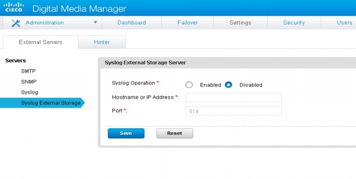
•![]() You need to configure Garbage Collector (GC) log in AAI (see Figure 1-3 and Figure 1-4) and configure external syslog through DMM GUI (see Figure 1-5) on both primary server and secondary server before cluster activation, to make sure that the functions work as expected. If the failover cluster has already been activated, configure the GC log and external syslog server on the active server, and then trigger a failover to configure the same settings on the standby server. Because the external syslog server page configuration is not porting as part of DRBD sync.
You need to configure Garbage Collector (GC) log in AAI (see Figure 1-3 and Figure 1-4) and configure external syslog through DMM GUI (see Figure 1-5) on both primary server and secondary server before cluster activation, to make sure that the functions work as expected. If the failover cluster has already been activated, configure the GC log and external syslog server on the active server, and then trigger a failover to configure the same settings on the standby server. Because the external syslog server page configuration is not porting as part of DRBD sync.
Figure 1-3 GC Log Option in AAI
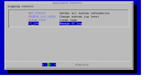
Figure 1-4 GC Log Configuration
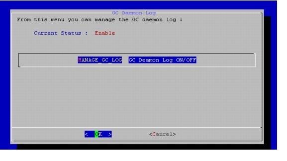
Figure 1-5 External Syslog Server Configuration
Important Notes for Failover Configuration
•![]() Install external certificates on the primary pair of appliances before configuring failover. When the certificates expire, use the virtual FQDN when obtaining new certificates. Install the new certificates using the virtual FQDN to access the AAI interface.
Install external certificates on the primary pair of appliances before configuring failover. When the certificates expire, use the virtual FQDN when obtaining new certificates. Install the new certificates using the virtual FQDN to access the AAI interface.
•![]() Back up your failover cluster (using the virtual FQDN to access AAI) immediately after configuring failover. Backups taken in standalone mode cannot be restored on a failover cluster.
Back up your failover cluster (using the virtual FQDN to access AAI) immediately after configuring failover. Backups taken in standalone mode cannot be restored on a failover cluster.
•![]() When using a switched interface for the replication interface connection, you need to make sure that the latency between the active and standby device is no more than 10 seconds. Latency of greater than 10 seconds will cause 10 consecutive heartbeat messages to be missed, initiating a failover.
When using a switched interface for the replication interface connection, you need to make sure that the latency between the active and standby device is no more than 10 seconds. Latency of greater than 10 seconds will cause 10 consecutive heartbeat messages to be missed, initiating a failover.
•![]() Restoring data on a Cisco Show and Share appliance in a failover cluster causes the Cisco Show and Share to reboot, initiating failover. This is expected behavior. The data is written to the standby appliance during the restore, so when the standby appliance becomes active it will contain the correct data.
Restoring data on a Cisco Show and Share appliance in a failover cluster causes the Cisco Show and Share to reboot, initiating failover. This is expected behavior. The data is written to the standby appliance during the restore, so when the standby appliance becomes active it will contain the correct data.
•![]() In a switched configuration, the switch interfaces connected to the replication interfaces must be configured for 1000 Mbps.
In a switched configuration, the switch interfaces connected to the replication interfaces must be configured for 1000 Mbps.
What to Do Next
•![]() To configure failover for a Cisco Digital Signs implementation, see Configure Failover for Cisco Digital Signs
To configure failover for a Cisco Digital Signs implementation, see Configure Failover for Cisco Digital Signs
•![]() To configure alerts and monitor your appliances, see Monitor and Control Failover.
To configure alerts and monitor your appliances, see Monitor and Control Failover.
•![]() To recover from a failover event, see Recover from a Failover.
To recover from a failover event, see Recover from a Failover.
 Feedback