Cisco UCS B440 High Performance Blade Server Installation and Service Note
Available Languages
Table Of Contents
Cisco UCS B440 High Performance Blade Server Installation and Service Note
Installing and Removing a Blade Server Hard Drive
Removing a Blade Server Hard Drive
Installing a Blade Server Hard Drive
Removing and Installing a UCS B440 High Performance Blade Server
Shutting Down and Powering Off A Blade Server
Removing a Cisco UCS B440 High Performance Blade Server
Installing a Cisco UCS B440 High Performance Blade Server
topicWorking Inside the Blade Server
Installing a Motherboard CMOS Battery
Installing a RAID Battery Backup Unit (BBU)
Obtaining Documentation and Submitting a Service Request
Cisco UCS B440 High Performance Blade Server Installation and Service Note
(N20-B6740-2)The Cisco UCS B440 High Performance Blade Servers (shown in Figure 1) are based on industry-standard server technologies and provide the following:
•
Up to four Intel Xeon 7500 Series processors
•
•
•
•
•
•
•
M1 and M2 versions are available, supporting different processor classes.
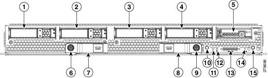
Figure 1 Cisco UCS B440 Front Panel

Note
LEDs
The LED indicators indicate whether the blade server is in active or standby mode, the status of the network link, the overall health of the blade server, and whether the server is set to give a flashing blue beaconing indication. The removable hard disks also have LEDs indicating hard disk access activity and hard disk health.
Buttons
The Reset button is just inside the chassis and must be pressed using the tip of a paper clip or a similar item. Hold the button down for five seconds and then release it to restart the server if other methods of restarting are not working.
The beaconing function for an individual server may be turned on or off by pressing the combination button and LED.
The Power button and LED allows you to manually take a server temporarily out of service but leave it in a state where it can be restarted quickly. If the desired power state for a service profile associated with a blade server or an integrated rack-mount server is set to "off", using the power button or Cisco UCS Manager to reset the server will cause the desired power state of the server to become out of sync with the actual power state and the server may unexpected shutdown at a later time. To safely reboot a server from a power-down state, use the Boot Server action in Cisco UCS Manager.
Connectors
A console port is provided to give a direct connection to a blade server to allow operating system installation and other management tasks to be done directly rather than remotely. The port uses the KVM dongle device included in the chassis accessory kit.
The KVM cable (N20-BKVM) shown in Figure 2 allows a KVM onnection into a Cisco UCS blade server, providing a DB9 serial connector, a VGA connector for a monitor, and dual USB ports for a keyboard and mouse. With this cable you can create a direct connection to the operating system and the BIOS running on a blade server. The pinout for the DB-9 connector is shown in Table 2.
Figure 2 KVM Cable for Blade Servers
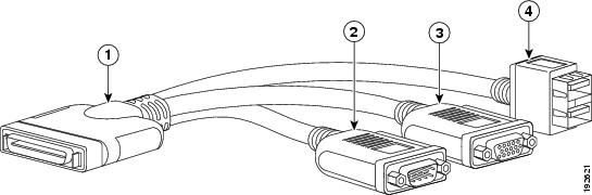
Connector to blade server
DB9 serial connector
VGA connection for a monitor
2-port USB connector for a mouse and keyboard
Table 2 DB-9 Connector Pinout
DCD
1
RX
2
TX
3
DTR
71
GND
5
DSR
6
RTS
41
CTS
8
RI
9
1 UCS 440 only.
Conventions
This document uses the following conventions for notes, cautions, and safety warnings.
Notes and Cautions contain important information that you should know.
Note

Caution
Safety warnings appear throughout this publication in procedures that, if performed incorrectly, can cause physical injuries. A warning symbol precedes each warning statement.
WarningIMPORTANT SAFETY INSTRUCTIONS
This warning symbol means danger. You are in a situation that could cause bodily injury. Before you work on any equipment, be aware of the hazards involved with electrical circuitry and be familiar with standard practices for preventing accidents. Use the statement number provided at the end of each warning to locate its translation in the translated safety warnings that accompanied this device. Statement 1071
SAVE THESE INSTRUCTIONS
Waarschuwing
BELANGRIJKE VEILIGHEIDSINSTRUCTIES
Dit waarschuwingssymbool betekent gevaar. U verkeert in een situatie die lichamelijk letsel kan veroorzaken. Voordat u aan enige apparatuur gaat werken, dient u zich bewust te zijn van de bij elektrische schakelingen betrokken risico's en dient u op de hoogte te zijn van de standaard praktijken om ongelukken te voorkomen. Gebruik het nummer van de verklaring onderaan de waarschuwing als u een vertaling van de waarschuwing die bij het apparaat wordt geleverd, wilt raadplegen.
BEWAAR DEZE INSTRUCTIES
Varoitus
TÄRKEITÄ TURVALLISUUSOHJEITA
Tämä varoitusmerkki merkitsee vaaraa. Tilanne voi aiheuttaa ruumiillisia vammoja. Ennen kuin käsittelet laitteistoa, huomioi sähköpiirien käsittelemiseen liittyvät riskit ja tutustu onnettomuuksien yleisiin ehkäisytapoihin. Turvallisuusvaroitusten käännökset löytyvät laitteen mukana toimitettujen käännettyjen turvallisuusvaroitusten joukosta varoitusten lopussa näkyvien lausuntonumeroiden avulla.
SÄILYTÄ NÄMÄ OHJEET
Attention
IMPORTANTES INFORMATIONS DE SÉCURITÉ
Ce symbole d'avertissement indique un danger. Vous vous trouvez dans une situation pouvant entraîner des blessures ou des dommages corporels. Avant de travailler sur un équipement, soyez conscient des dangers liés aux circuits électriques et familiarisez-vous avec les procédures couramment utilisées pour éviter les accidents. Pour prendre connaissance des traductions des avertissements figurant dans les consignes de sécurité traduites qui accompagnent cet appareil, référez-vous au numéro de l'instruction situé à la fin de chaque avertissement.
CONSERVEZ CES INFORMATIONS
Warnung
WICHTIGE SICHERHEITSHINWEISE
Dieses Warnsymbol bedeutet Gefahr. Sie befinden sich in einer Situation, die zu Verletzungen führen kann. Machen Sie sich vor der Arbeit mit Geräten mit den Gefahren elektrischer Schaltungen und den üblichen Verfahren zur Vorbeugung vor Unfällen vertraut. Suchen Sie mit der am Ende jeder Warnung angegebenen Anweisungsnummer nach der jeweiligen Übersetzung in den übersetzten Sicherheitshinweisen, die zusammen mit diesem Gerät ausgeliefert wurden.
BEWAHREN SIE DIESE HINWEISE GUT AUF.
Avvertenza
IMPORTANTI ISTRUZIONI SULLA SICUREZZA
Questo simbolo di avvertenza indica un pericolo. La situazione potrebbe causare infortuni alle persone. Prima di intervenire su qualsiasi apparecchiatura, occorre essere al corrente dei pericoli relativi ai circuiti elettrici e conoscere le procedure standard per la prevenzione di incidenti. Utilizzare il numero di istruzione presente alla fine di ciascuna avvertenza per individuare le traduzioni delle avvertenze riportate in questo documento.
CONSERVARE QUESTE ISTRUZIONI
Advarsel
VIKTIGE SIKKERHETSINSTRUKSJONER
Dette advarselssymbolet betyr fare. Du er i en situasjon som kan føre til skade på person. Før du begynner å arbeide med noe av utstyret, må du være oppmerksom på farene forbundet med elektriske kretser, og kjenne til standardprosedyrer for å forhindre ulykker. Bruk nummeret i slutten av hver advarsel for å finne oversettelsen i de oversatte sikkerhetsadvarslene som fulgte med denne enheten.
TA VARE PÅ DISSE INSTRUKSJONENE
Aviso
INSTRUÇÕES IMPORTANTES DE SEGURANÇA
Este símbolo de aviso significa perigo. Você está em uma situação que poderá ser causadora de lesões corporais. Antes de iniciar a utilização de qualquer equipamento, tenha conhecimento dos perigos envolvidos no manuseio de circuitos elétricos e familiarize-se com as práticas habituais de prevenção de acidentes. Utilize o número da instrução fornecido ao final de cada aviso para localizar sua tradução nos avisos de segurança traduzidos que acompanham este dispositivo.
GUARDE ESTAS INSTRUÇÕES
¡Advertencia!
INSTRUCCIONES IMPORTANTES DE SEGURIDAD
Este símbolo de aviso indica peligro. Existe riesgo para su integridad física. Antes de manipular cualquier equipo, considere los riesgos de la corriente eléctrica y familiarícese con los procedimientos estándar de prevención de accidentes. Al final de cada advertencia encontrará el número que le ayudará a encontrar el texto traducido en el apartado de traducciones que acompaña a este dispositivo.
GUARDE ESTAS INSTRUCCIONES
Varning!
VIKTIGA SÄKERHETSANVISNINGAR
Denna varningssignal signalerar fara. Du befinner dig i en situation som kan leda till personskada. Innan du utför arbete på någon utrustning måste du vara medveten om farorna med elkretsar och känna till vanliga förfaranden för att förebygga olyckor. Använd det nummer som finns i slutet av varje varning för att hitta dess översättning i de översatta säkerhetsvarningar som medföljer denna anordning.
SPARA DESSA ANVISNINGAR


Aviso
INSTRUÇÕES IMPORTANTES DE SEGURANÇA
Este símbolo de aviso significa perigo. Você se encontra em uma situação em que há risco de lesões corporais. Antes de trabalhar com qualquer equipamento, esteja ciente dos riscos que envolvem os circuitos elétricos e familiarize-se com as práticas padrão de prevenção de acidentes. Use o número da declaração fornecido ao final de cada aviso para localizar sua tradução nos avisos de segurança traduzidos que acompanham o dispositivo.
GUARDE ESTAS INSTRUÇÕES
Advarsel
VIGTIGE SIKKERHEDSANVISNINGER
Dette advarselssymbol betyder fare. Du befinder dig i en situation med risiko for legemesbeskadigelse. Før du begynder arbejde på udstyr, skal du være opmærksom på de involverede risici, der er ved elektriske kredsløb, og du skal sætte dig ind i standardprocedurer til undgåelse af ulykker. Brug erklæringsnummeret efter hver advarsel for at finde oversættelsen i de oversatte advarsler, der fulgte med denne enhed.
GEM DISSE ANVISNINGER


Installing and Removing a Blade Server Hard Drive
There are up to 4 front-accessible, hot-swappable, 2.5-inch SAS or SATA drives per blade. You can remove blade server hard drives without removing the blade server from the chassis. All other component replacement for a blade server requires removing the blade from the chassis. Unused hard drive bays should always be covered with cover plates (N20-BBLKD) to assure proper cooling and ventilation. The chassis is omitted from illustrations here to simplify the drawing.
Caution
Replacing an HDD or SSD with a drive of the same size, model, and manufacturer generally causes few problems with UCS Manager. If the drive being replaced was part of a RAID array we recommend using a newly ordered drive of identical size, model, and manufacturer to replace the failed drive. Cisco recommends following industry standard practice of using drives of the same capacity when creating RAID volumes. If drives of different capacities are used, the useable portion of the smallest drive will be used on all drives that make up the RAID volume. Before upgrading or adding an HDD to a running system, check the service profile in UCS Manager and make sure the new hardware configuration will be within the parameters allowed by the service profile.
Hard disk and RAID troubleshooting information is in the Troubleshooting Server Hardware chapter of the Cisco UCS Troubleshooting Guide. The B440 uses an LSI SAS 2108 RAID controller (the onboard version of the LSI MegaRAID 9260).
Table 3 shows the drives supported in this blade server.
Table 3 Supported Hard Disk Drives (HDD)
A03-D073GC2
73 GB, 6Gb SAS transfer rate, 15K RPM HDD/hot plug/drive sled mounted
A03-D146GC2
146 GB 6Gb SAS transfer rate, 15k RPM SFF HDD/hot plug/drive sled mounted
A03-D300GA2
300 GB, 6Gb SAS transfer rate, 10K RPM HDD/hot plug/drive sled mounted
A03-D100SSD
100 GB SATA SSD HDD/hot plug/drive sled mounted (no longer sold)
UCS-SSD100GI1F104
100 GB SATA SSD HDD/hot plug/drive sled mounted
A03-D600GA2
600 GB, 6Gb SAS transfer rate, 10K RPM HDD/hot plug/drive sled mounted
UCS-HDD300GI2F105
300GB 6Gb SAS 15K RPM SFF HDD/hot plug/drive sled mounted1
UCS-HDD900GI2F106
900GB 6Gb SAS 10K RPM SFF HDD/hot plug/drive sled mounted2
1 This drive requires UCS capability catalog version 1.0.50.T or 2.0.1nT or later.
2 This drive requires UCS capability catalog version 1.0.54.T or 2.0.1pT or later.
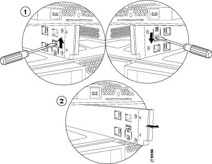
Removing a Blade Server Hard Drive
To remove a hard drive from a blade server, follow these steps:
Step 1
Step 2
Step 3
Figure 3 Removing and Installing a Hard Drive
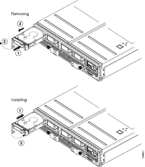
Installing a Blade Server Hard Drive
To install a blade server hard drive, follow these steps:
Step 1
Step 2
Step 3
You can use UCS Manager to format and configure RAID services. refer to the UCS Manager configuration guide for your software release for details on RAID configuration.
If you need to move a RAID cluster, refer to the Moving a RAID Cluster section of the the Troubleshooting Server Hardware chapter of the Cisco UCS Troubleshooting Guide.
Removing and Installing a UCS B440 High Performance Blade Server
Before performing any internal operation on a blade server, you must turn it off and remove it from the chassis.
Caution
Shutting Down and Powering Off A Blade Server
The server can run in two power modes:
•
•
After establishing a connection to the blade server's operating system, you can directly shut down the blade server using the operating system.
You can invoke a graceful shutdown or an emergency shutdown (hard shutdown) by using either of the following methods:
•
•
Step 1
•
•
Step 2
Caution
•
•
Step 3
Removing a Cisco UCS B440 High Performance Blade Server
Using UCS Manager, decommission the server using UCS Manager before physically removing the server. To remove a blade server from the chassis, follow these steps:
Step 1
Step 2
Step 3
Step 4
Step 5
Step 6
Installing a Cisco UCS B440 High Performance Blade Server
While the blades and chassis are designed for any device to operate in any slot, the following placement guidelines should be used when installing blades to distribute weight as intended and make insertion and removal easier:
1.
2.
To install a blade server, follow these steps:
Step 1
a.
b.

Tip
Figure 4 Removing a Chassis Partition
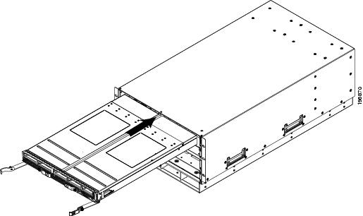
Step 2
Figure 5 Positioning a Blade Server in the Chassis
Step 3
Step 4
Step 5
Step 6
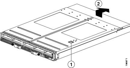
Removing a Blade Server Cover
To open a blade server, follow these steps:
Step 1
Step 2
Figure 6 Opening a Blade Server
Internal Components
Figure 7 calls out the various components within the blade server.
Figure 7 Inside View of a Blade Server
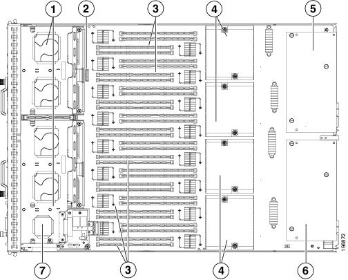
Hard drive bays
CMOS Battery
DIMM slots
CPU and heat sink
Adapter card in Slot 0
Adapter card in Slot 1
RAID BBU
Diagnostics Button and LEDs
At blade start-up, POST diagnostics test the CPUs, DIMMs, HDDs and adapter cards, and any failure notifications are sent to UCSM. You can view these notification in the System Error Log or in the output of the show tech-support command. If errors are found, an amber diagnostic LED will also light up next to the failed component. During run time, the blade BIOS, component drivers, and OS all monitor for hardware faults and will light up the amber diagnostic LED for a component if an uncorrectable error or correctable errors (such as a host ECC error) over the allowed threshold occur.
LED states are saved, and if you remove the blade from the chassis the LED values will persist for up to 10 minutes. Pressing the LED diagnostics button on the motherboard will cause the LEDs that currently show a component fault to light for up to 30 seconds for easier component identification. LED fault values are reset when the blade is reinserted into the chassis and booted, and the process begins from its start.
If DIMM insertion errors are detected, they may cause the blade discovery to fail and errors will be reported in the server POST information, viewable using the UCS Manager GUI or CLI. UCS blade servers require specific rules to be followed when populating DIMMs in a blade server, and the rules depend on the blade server model. Refer to the documentation for a specific blade server for those rules.
HDD status LEDs are on the front face of the HDD. Faults on the CPU, DIMMs, or adapter cards will also cause the server health LED to light solid Amber for minor error conditions or blinking Amber for critical error conditions.
topicWorking Inside the Blade Server
This section describes how to perform the following tasks within a blade server:
•
•
•
•
Installing a Motherboard CMOS Battery
This server supports the following Cisco components and part numbers.
Warning
Statement 1015To install or replace a motherboard complementary metal-oxide semiconductor (CMOS) battery, follow these steps:
Step 1
a.
b.
c.
d.
e.
Step 2
a.
b.
c.
d.
Figure 8 Removing and Replacing a Motherboard CMOS Battery
Removing a CPU or Heat Sink
You can order your blade server with one CPUs, and upgrade later to up to four CPUs. All CPUs must be of the same type, and memory in slots intended for additional CPUs will not be recognized if the corresponding CPU is not present (see Memory Arrangement). You may need to use these procedures to move a CPU from one server to another, or to replace a faulty CPU.
Table 4 and Table 5 show the available CPU options:
Table 4 CPU Options, M1 Models
A01-X0200 / Xeon X7560
130 W
2.26 GHz
24 MB
A01-X0201 / Xeon X7550
130 W
2.00 GHz
18 MB
A01-X0203 / Xeon E7540
105 W
2.00GHz
18 MB
A01-X0206 / Xeon L7555
95 W
1.86 GHz
24 MB
A01-X0209 / Xeon E7520
95 W
1.86GHz
18 MB
Table 5 CPU Options, M2 Models
UCS-CPU-E74870
130 W
2.4 GHz
30 MB
UCS-CPU-E74860
130 W
2.26 GHz
24 MB
UCS-CPU-E74850
130 W
2.00 GHz
24 MB
UCS-CPU-E74830
105 W
2.13 GHz
24 MB
UCS-CPU-E74807
95 W
1.86 GHz
18 MB
UCS-CPU-E78867L
105 W
2.13 GHz
30 MB
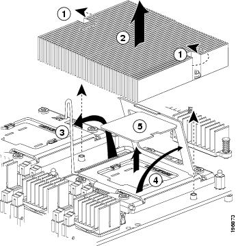
To remove a CPU, CPU filler, or heat sink, follow these steps:
Step 1
Step 2
Step 3
Step 4
Step 5
Figure 9 Removing the Heat Sink and Accessing the CPU Socket
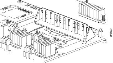
If a replacement CPU will not be used and the CPU will be left vacant, you should have an air blocker installed rather than a heat sink. The air blocker assures that air flows where it is needed, and is shown in Figure 10.
Figure 10 CPU Air Blocker
Installing a CPU or Heat Sink
Before installing a new CPU in a server, verify the following:
•
•
•
To install a CPU or heat sink, follow these steps:
Step 1
Figure 11 Inserting the CPU and Replacing the Heat Sink
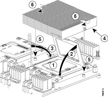
Step 2
Step 3
Step 4
Step 5
Step 6
Caution
Installing Memory
Check the server's service profile setting in UCS Manager before adding memory to make sure that the new memory will be recognized. To install a DIMM into the blade server, follow these steps:
Step 1
Figure 12 Installing DIMMs in the Blade Server
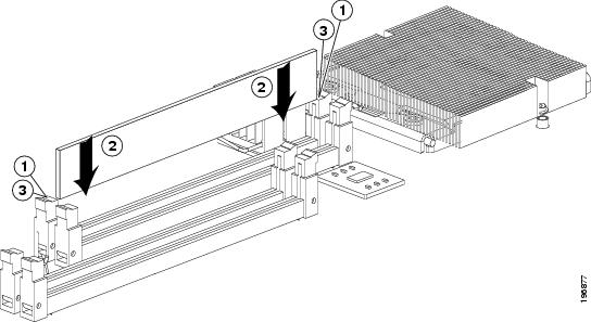
Step 2
Note
Step 3
Memory and Performance
This section describes the type of memory that the blade server requires, and its effect on performance. The following topics are covered:
Modern processors are designed to support several generations of memory technology. Cisco's Extended Memory Technology allows us to replace high-density DIMMs with multiple lower-density DIMMs in a way that is transparent to the processor and to applications. In some configurations, we are emulating DIMMs that are not available, such as making four 8-GB DIMMs appear to be a single 32-GB DIMM. In other cases we can emulate high cost-per-bit DIMMs with multiple low cost-per-bit DIMMs; for example, making four 4 GB DIMMs emulate a 16 GB DIMM.
Supported DIMMs
Table 6 and Table 7 list the type of DIMMs that Cisco Systems makes available for use with this blade server:
Table 6 Cisco Systems Supported DIMMs (M1 Models)
A02-M308GB3-2
Two DIMMs, each 4 GB DDR3-1066 MHz (Low Voltage supported)
A02-M316GB3-2
Two DIMMs, each 8GB DDR3-1066 MHz (Low Voltage supported)
A02-M332GB3-2-L
Two DIMMs, each 16 GB DDR3-1066 MHz (Low Voltage supported)
UCS-MR-2X041RX-C
Two DIMMs, each 4 GB DDR3-1333 MHz (Low Voltage supported)
Table 7 Cisco Systems Supported DIMMs (M2 Models)
A02-M308GB3-2
Two DIMMs, each 4 GB DDR3-1066 MHz (Low Voltage supported)
A02-M316GB3-2
Two DIMMs, each 8 GB DDR3-1066 MHz (Low Voltage supported)
A02-M332GB3-2-L
Two DIMMs, each 16 GB DDR3-1066 MHz (Low Voltage supported)
A02-M308GD5-2
Two DIMMs, each 4 GB DDR3-1333 MHz
A02-M316GD5-2
Two DIMMs, each 8 GB DDR3-1333 MHz
UCS-MR-2X324RX-C
Two DIMMs, each 32 GB DDR3-1333 MHz (Low Voltage supported)1
1 Capability catalog 2.0(1m)T or later is required.
Caution
Cisco does not support third-party memory DIMMs, and in some cases their use may irreparably damage the server and require an RMA and down time.
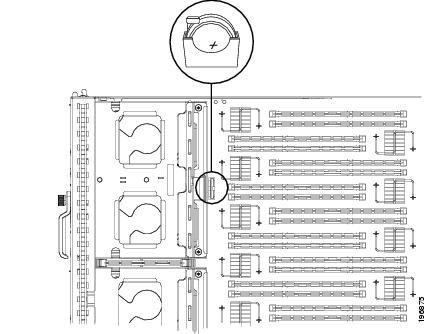
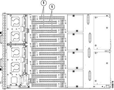
Memory Arrangement
The Cisco UCS B440 high-performance blade server contains 32 slots for installing DIMMs—8 for each CPU. Each CPU has 8 DIMM slots and DDR channels, with 4 pairs of DIMMs operating in lockstep (see Figure 13) so you must install additional DIMMs in pairs, as laid out in Table 8. This blade server needs at least one matched pair of DIMMs attached to CPU 1 or CPU 2. All four CPUs can boot and run from a single DIMM pair. DIMM pairs must be identical, but one DIMM pair on a CPU can be different from other pairs. DIMMs installed in slots for an absent CPU will not be recognized. For optimal performance, distribute DIMMs evenly across all CPUs. DIMM connector latches are color coded blue, yellow, black, and white, and Cisco recommends installing memory in that order. It is also recommended to install memory evenly across the installed CPUs.
Figure 13 Memory Slots Within the Blade Server
Channels
Each CPU has 8 channels, consisting of 4 matched pairs. Each channel pair is identified by a letter: A, B, C, or D for each CPU. Each channel pair member is identified by numbers, either 1 or 0.
Figure 14 shows how channels are physically laid out on the blade server. The DIMM slots are to the left of their associated CPU. When installing DIMMs, you must add them in pairs in the configurations shown in Table 8:
Table 8 Adding DIMMs to a CPU
2 (blue)
(A0, A1)
4 (blue, white )
(A0, A1)-(C0, C1)
8 (blue, white, yellow, and black)
(A0, A1)-(C0, C1)-(B0, B1)-( D0, D1)
Note
Figure 14 Physical Representation of DIMMs for a CPU
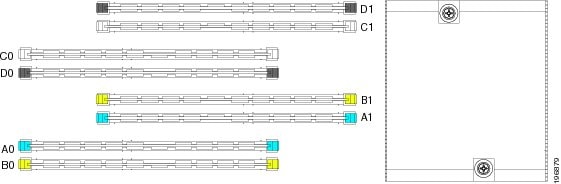
Figure 15 shows a logical view of the channels.
Figure 15 Logical Representation of Channels
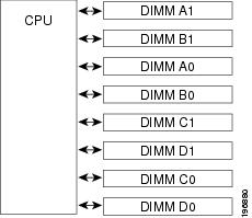
DIMMs can be used in the High-performance blade server using the slot pairs described in Table 8.
Memory Performance
When configuring your server, consider the following.
•
•
Bandwidth and Performance
You can achieve maximum bandwidth, performance, and system memory using the following configuration:
•
•
•
Note
Performance Loss
Performance is less than optimal if the following memory configurations are used:
•
•
Depending on the application needed, performance loss might or might not be noticeable or measurable. Partially populating a pair is unsupported, and will not work at all.
Installing an Adapter Card
The network adapters and interface cards all have a shared installation process. The following options are available:
Table 9 Adapter Card Options
N20-AQ0002 or
N20-AE0002Cisco UCS M71KR-E/Q Converged Network Adapter
N20-AC0002
Cisco UCS M81KR Virtual Interface Card
N20-AB0002
Cisco UCS NIC M51KR-B Broadcom BCM57711 Network Adapter
N20-AI0102
Cisco UCS CNA M61KR-I Intel Converged Network Adapter1
N20-AQ0102
Cisco UCS CNA M72KR-Q QLogic Converged Network Adapter
N20-AE0102
Cisco UCS CNA M72KR-E Emulex Converged Network Adapter
UCS-VIC-M82-8P
Cisco UCS Virtual Interface Card 12802
2 Requires UCS Manager 2.0(2) or later.
If you are switching from one type of card to another, before you physically perform the switch make sure you have downloaded the latest device drivers and loaded them into the server's OS. For the most recent details, refer to the firmware management chapter of one of the UCS Manager software configuration guides.
Adapter cards can be installed in either slot 1 or slot 0; they can be of the same type or as of UCS Manager 1.3(1), the following mixed configurations are supported:
•
•
To install an adapter card on the blade server, follow these steps:
Step 1
Step 2
Step 3
Figure 16 Installing an Adapter Card
Installing a RAID License Key
Depending on the RAID license key that is installed, the onboard RAID controller supports the following RAID levels:
•
•
•
•
•
•
•
The Cisco RAID key is OEM version of LSI MegaRAID SAS 8880EM2 SGL. If a replacement is needed, the stock LSI version will not work as a replacement as the physical connector is different, you must order replacements from Cisco.
User information for RAID controllers is in the Cisco UCS Servers RAID Guide.
To install a RAID license key, follow these steps:
Step 1
Step 2
Figure 17 Installing a RAID License Key
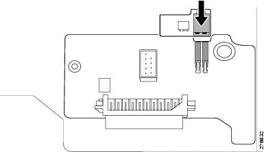
When fully installed, the "RAID KEY" label on the daughter card will be covered by the key.
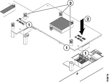
Installing a RAID Battery Backup Unit (BBU)
The BBU is an intelligent battery backup unit that protects disk write cache data during a power loss on the RAID controller for up to 72 hours. We recommend that you replace the BBU once per year or after 1,000 recharge cycles, whichever comes first. Verify whether BBU replacement is required by using the show raid-battery detail command in the CLI.
To remove the RAID license key, perform the following procedure in reverse order.
To install a RAID BBU, follow these steps:
Step 1
Step 2
Step 3
Figure 18 Slide in the BBU
.
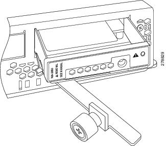
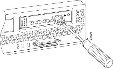
Step 4
Step 5
Figure 19 Tighten the Captive Screw
Server Troubleshooting
For general server troubleshooting information, refer to the Troubleshooting Server Hardware chapter of the Cisco UCS Troubleshooting Guide.
Server Configuration
UCS servers are intended to be configured and managed using UCS Manager. Refer to the UCS Manager Configuration Guide appropriate for your UCS Manager version.
Server Specifications
Table 10 Physical Specifications for the Cisco UCS B440 Blade Server
Height
1.95 inches (50 mm)
Width
16.50 inches (419.1 mm)
Depth
24.4 inches (620 mm)
Weight
34.5 lbs (15.65 kg) 1
1 The system weight listed here is an estimate for a fully configured system and will vary depending on peripheral devices installed.
Related Documentation
The documentation set for the Cisco Unified Computing System environment is described in full at:
http://www.cisco.com/go/unifiedcomputing/b-series-doc
Obtaining Documentation and Submitting a Service Request
For information on obtaining documentation, submitting a service request, and gathering additional information, see the monthly What's New in Cisco Product Documentation, which also lists all new and revised Cisco technical documentation, at:
http://www.cisco.com/en/US/docs/general/whatsnew/whatsnew.html
Subscribe to the What's New in Cisco Product Documentation as an RSS feed and set content to be delivered directly to your desktop using a reader application. The RSS feeds are a free service. Cisco currently supports RSS Version 2.0.
Cisco and the Cisco logo are trademarks or registered trademarks of Cisco and/or its affiliates in the U.S. and other countries. To view a list of Cisco trademarks, go to this URL: www.cisco.com/go/trademarks. Third-party trademarks mentioned are the property of their respective owners. The use of the word partner does not imply a partnership relationship between Cisco and any other company. (1110R)
Any Internet Protocol (IP) addresses and phone numbers used in this document are not intended to be actual addresses and phone numbers. Any examples, command display output, network topology diagrams, and other figures included in the document are shown for illustrative purposes only. Any use of actual IP addresses or phone numbers in illustrative content is unintentional and coincidental.
© 2010 Cisco Systems, Inc. All rights reserved.


 Feedback
Contact Cisco
- Open a Support Case

- (Requires a Cisco Service Contract)