Cisco UCS B420 M3 High Performance Blade Server
This document describes how to install and service the Cisco UCS B420 M3 High Performance Blade Server, a full-width blade server meaning up to four of these high-density, four-socket blade servers can reside in a Cisco UCS 5108 Blade Server chassis.
The B420 M3 Blade Server has the following features:
-
Up to four Intel Xeon processor E5-4600 processor family CPUs, with up to 32 cores per server
-
48 DIMM slots for registered ECC DIMMs, with up to 1.5-TB memory capacity (using 32-GB LRDIMMs)
-
3 adapter connectors for up to 160-Gb/s bandwidth:
-
One dedicated connector for the Cisco VIC 1240 modular LAN-on-motherboard (mLOM)
-
Two connectors for Cisco the VIC 1280, VIC Port Expander, or third-party network adapter cards
-
-
Four hot-plug drive bays that support SAS or SATA SSD drives
-
LSI 2208R controller that provides RAID 0, 1, 5, and 10 with an optional 1-GB flash-backed write cache
|
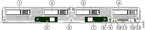
1 |
Drive bay 1 |
8 |
Power button and LED |
|
2 |
Drive bay 2 |
9 |
Network link status LED |
|
3 |
Drive bay 3 |
10 |
Blade health LED |
|
4 |
Drive bay 4 |
11 |
Local console connection |
|
5 |
Left ejector handle |
12 |
Reset button access |
|
6 |
Asset Tag Each server has a blank plastic tag that pulls out of the front panel so you can add your own asset tracking label without interfering with the intended air flow. |
13 |
Beaconing button and LED |
|
7 |
Right ejector handle |
LEDs
Server LEDs indicate whether the blade server is in active or standby mode, the status of the network link, the overall health of the blade server, and whether the server is set to give a blinking blue locator light from the locator button.
The removable drives also have LEDs indicating hard disk access activity and disk health.
|
LED |
Color |
Description |
|
|---|---|---|---|
|
Power  |
Off |
Power off. |
|
|
Green |
Main power state. Power is supplied to all server components and the server is operating normally. |
||
|
Amber |
Standby power state. Power is supplied only to the service processor of the server so that the server can still be managed.
|
||
|
Link  |
Off |
None of the network links are up. |
|
|
Green |
At least one network link is up. |
||
|
Health  |
Off |
Power off. |
|
|
Green |
Normal operation. |
||
|
Amber |
Minor error. |
||
|
Blinking Amber |
Critical error. |
||
|
Blue locator button and LED  |
Off |
Blinking is not enabled. |
|
|
Blinking blue 1 Hz |
Blinking to locate a selected blade—If the LED is not blinking, the blade is not selected. You can control the blinking in UCS Manager or by using the blue locator button/LED. |
||
|
Activity (Disk Drive)  |
Off |
Inactive. |
|
|
Green |
Outstanding I/O to disk drive. |
||
|
Health (Disk Drive) |
Off |
Can mean either no fault detected or the drive is not installed. |
|
|
Flashing Amber 4 hz |
Rebuild drive active. If the Activity LED is also flashing amber, a drive rebuild is in progress. |
||
|
Amber |
Fault detected. |
Buttons
The Reset button is recessed in the front panel of the server. You can press the button with the tip of a paper clip or a similar item. Hold the button down for five seconds, and then release it to restart the server if other methods of restarting do not work.
The locator function for an individual server may get turned on or off by pressing the locator button/LED.
The front-panel power button is disabled by default. It can re-enabled through Cisco UCS Manager. After it's enabled, The power button allows you to manually take a server temporarily out of service but leave it in a state where it can be restarted quickly. If the desired power state for a service profile associated with a blade server is set to "off," using the power button or Cisco UCS Manager to reset the server will cause the desired power state of the server to become out of sync with the actual power state and the server may unexpectedly shut down at a later time. To safely reboot a server from a power-down state, use the Boot Server action in Cisco UCS Manager.
Local Console Connection
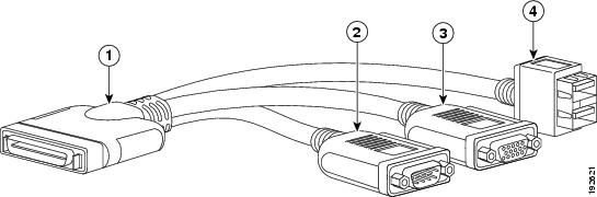
The local console connector allows a direct connection to a blade server to allow operating system installation and other management tasks to be done directly rather than remotely. The port uses the KVM dongle cable that provides a connection into a Cisco UCS blade server; it has a DB9 serial connector, a VGA connector for a monitor, and dual USB ports for a keyboard and mouse. With this cable, you can create a direct connection to the operating system and the BIOS running on a blade server. A KVM cable ships standard with each blade chassis accessory kit.
|
1 |
Connector to blade server local console connection |
2 |
DB9 serial connector |
|
3 |
VGA connector for a monitor |
4 |
2-port USB connector for a mouse and keyboard |
Drive Replacement
Each blade has up to four front-accessible, hot plug capable, 2.5-inch SAS or SATA drive bays. Unused hard drive bays should always be covered with cover plates to ensure proper cooling and ventilation.
You can remove and install hard drives without removing the blade server from the chassis.
The drives supported in this blade server come with the drive sled attached. Spare drive sleds are not available. A list of currently supported drives is in the specification sheets at this URL:http://www.cisco.com/c/en/us/products/servers-unified-computing/ucs-b-series-blade-servers/datasheet-listing.html
Before upgrading or adding a drive to a running blade server, check the service profile in Cisco UCS Manager and make sure the new hardware configuration will be within the parameters allowed by the service profile.
 Caution |
To prevent ESD damage, wear grounding wrist straps during these procedures. |
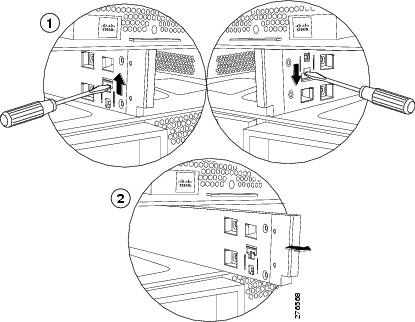
Removing a Blade Server Hard Drive
To remove a hard drive from a blade server, follow these steps:
SUMMARY STEPS
- Push the button to release the ejector, and then pull the hard drive from its slot.
- Place the hard drive on an antistatic mat or antistatic foam if you are not immediately reinstalling it in another server.
- Install a hard disk drive blank faceplate to keep dust out of the blade server if the slot will remain empty.
DETAILED STEPS
|
Step 1 |
Push the button to release the ejector, and then pull the hard drive from its slot. |
|
Step 2 |
Place the hard drive on an antistatic mat or antistatic foam if you are not immediately reinstalling it in another server. |
|
Step 3 |
Install a hard disk drive blank faceplate to keep dust out of the blade server if the slot will remain empty. 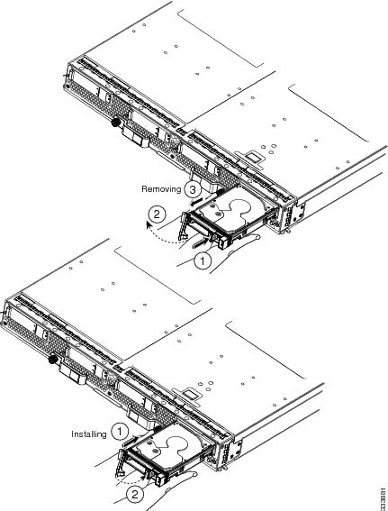 |
Installing a Blade Server Drive
To install a drive in a blade server, follow these steps:
SUMMARY STEPS
- Place the drive ejector into the open position by pushing the release button.
- Gently slide the drive into the opening in the blade server until it seats into place.
- Push the drive ejector into the closed position.
DETAILED STEPS
|
Step 1 |
Place the drive ejector into the open position by pushing the release button. |
|
Step 2 |
Gently slide the drive into the opening in the blade server until it seats into place. |
|
Step 3 |
Push the drive ejector into the closed position. You can use Cisco UCS Manager to format and configure RAID services. For details, see the Configuration Guide for the version of Cisco UCS Manager that you are using. The configuration guides are available at the following URL: http://www.cisco.com/en/US/products/ps10281/products_installation_and_configuration_guides_list.html If you need to move a RAID cluster, see the Cisco UCS Manager Troubleshooting Reference Guide. |
Basic Troubleshooting: Reseating a SAS/SATA Drive
Sometimes it is possible for a false positive UBAD error to occur on SAS/SATA HDDs installed in the server.
-
Only drives that are managed by the UCS MegaRAID controller are affected.
-
Drives can be affected regardless where they are installed in the server (front-loaded, rear-loaded, and so on).
-
Both SFF and LFF form factor drives can be affected.
-
Drives installed in all Cisco UCS C-Series servers with M3 processors and later can be affected.
-
Drives can be affected regardless of whether they are configured for hotplug or not.
-
The UBAD error is not always terminal, so the drive is not always defective or in need of repair or replacement. However, it is also possible that the error is terminal, and the drive will need replacement.
Before submitting the drive to the RMA process, it is a best practice to reseat the drive. If the false UBAD error exists, reseating the drive can clear it. If successful, reseating the drive reduces inconvenience, cost, and service interruption, and optimizes your server uptime.
 Note |
Reseat the drive only if a UBAD error occurs. Other errors are transient, and you should not attempt diagnostics and troubleshooting without the assistance of Cisco personnel. Contact Cisco TAC for assistance with other drive errors. |
To reseat the drive, see Reseating a SAS/SATA Drive.
Reseating a SAS/SATA Drive
Sometimes, SAS/SATA drives can throw a false UBAD error, and reseating the drive can clear the error.
Use the following procedure to reseat the drive.
Caution |
This procedure might require powering down the server. Powering down the server will cause a service interruption. |
Before you begin
Before attempting this procedure, be aware of the following:
-
Before reseating the drive, it is a best practice to back up any data on it.
-
When reseating the drive, make sure to reuse the same drive bay.
-
Do not move the drive to a different slot.
-
Do not move the drive to a different server.
-
If you do not reuse the same slot, the Cisco management software (for example, Cisco IMM) might require a rescan/rediscovery of the server.
-
-
When reseating the drive, allow 20 seconds between removal and reinsertion.
Procedure
|
Step 1 |
Attempt a hot reseat of the affected drive(s). Choose the appropriate option.
|
||
|
Step 2 |
During boot up, watch the drive's LEDs to verify correct operation. |
||
|
Step 3 |
If the error persists, cold reseat the drive, which requires a server power down. Choose the appropriate option: |
||
|
Step 4 |
If hot and cold reseating the drive (if necessary) does not clear the UBAD error, choose the appropriate option:
|
Blade Server Removal and Installation
Before performing any internal operations on this blade server, you must remove it from the chassis.
Caution |
To prevent ESD damage, wear grounding wrist straps during these procedures and handle modules by the carrier edges only. |
Powering Off a Blade Server Using the Power Button
Note |
The front panel power button is disabled by default to ensure that servers are decommissioned through the UCS management software interface before shutdown. If you prefer to shut down the server locally with the button, you can enable front power-button control in the UCS management software interface. |
 Tip |
You can also shut down servers remotely using the UCS management software interface. For details, see the configuration guide for the version the UCS management software interface that you are using. The configuration guides are available at the URLs documented in Server Configuration. |
Procedure
|
Step 1 |
If you are local to the server, check the color of the Power Status LED for each server in the chassis that you want to power off.
|
||
|
Step 2 |
If you previously enabled front power-button control through the UCS management software interface, press and release the Power button, then wait until the Power Status LED changes to amber. The operating system performs a graceful shutdown, and the server goes to standby mode.
|
||
|
Step 3 |
(Optional) Although not recommended, if you are shutting down all blade servers in a chassis, you can disconnect the power cords from the chassis to completely power off the servers.
|
Removing a Blade Server
You must decommission the server using Cisco UCS Manager before physically removing the blade server.
SUMMARY STEPS
- Turn off the blade server using either Cisco UCS Manager.
- Completely loosen the captive screws on the front of the blade.
- Remove the blade from the chassis by pulling the ejector levers on the blade until it unseats the blade server.
- Slide the blade part of the way out of the chassis, and place your other hand under the blade to support its weight.
- Once removed, place the blade on an antistatic mat or antistatic foam if you are not immediately reinstalling it.
- If the blade server slot is to remain empty, reinstall the slot divider and install two blade server blanking panels to maintain proper thermal temperatures and to keep dust out of the chassis.
DETAILED STEPS
|
Step 1 |
Turn off the blade server using either Cisco UCS Manager. |
|
Step 2 |
Completely loosen the captive screws on the front of the blade. |
|
Step 3 |
Remove the blade from the chassis by pulling the ejector levers on the blade until it unseats the blade server. |
|
Step 4 |
Slide the blade part of the way out of the chassis, and place your other hand under the blade to support its weight. |
|
Step 5 |
Once removed, place the blade on an antistatic mat or antistatic foam if you are not immediately reinstalling it. |
|
Step 6 |
If the blade server slot is to remain empty, reinstall the slot divider and install two blade server blanking panels to maintain proper thermal temperatures and to keep dust out of the chassis. |
Installing a Blade Server
For installations of UCS blades with differing widths and heights in a chassis, the guideline is to load the heaviest and largest blades at the bottom of the chassis. Therefore, if a UCS B460 blade server is present, it should be installed at the bottom, followed by full-width blades such as the UCS B420 or UCS B480 above the UCS B460, and then half-width blades such as the UCS B200 at the top of the chassis.
Before you begin
The blade server must have its cover installed before installing it into the chassis to ensure adequate airflow.
Procedure
|
Step 1 |
If necessary, remove the slot divider from the chassis.
|
||
|
Step 2 |
Grasp the front of the blade server and place your other hand under the blade to support it. 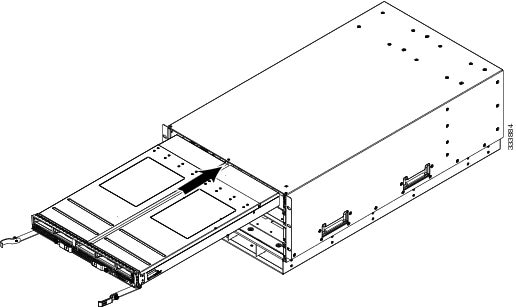 |
||
|
Step 3 |
Open the ejector levers in the front of the blade server. |
||
|
Step 4 |
Gently slide the blade into the opening until you cannot push it any farther. |
||
|
Step 5 |
Press the ejectors so that they catch the edge of the chassis and press the blade server all the way in. |
||
|
Step 6 |
Tighten the captive screw on the front of the blade to no more than 3 in-lbs. Tightening only with bare fingers is unlikely to lead to stripped or damaged captive screws. Cisco UCS Manager automatically reacknowledges, reassociates, and recommissions the server, provided any hardware changes are allowed by the service profile. |
Secure Digital Cards
Secure Digital (SD) card slots are provided and one or two SD cards can be populated. If two SD cards are populated, they can be used in a mirrored mode.
Note |
Do not mix different capacity cards in the same server. |
Note |
Due to technical limitations, if the server is running a Cisco UCS Manager version earlier than release 2.2(3a) with the 32-GB SD card, only 16-GB usable capacity is available (regardless of mirroring) in the server. |
Removing a Blade Server Cover
SUMMARY STEPS
- Press and hold the button down as shown in the figure below.
- While holding the back end of the cover, pull the cover back and then up.
DETAILED STEPS
|
Step 1 |
Press and hold the button down as shown in the figure below. |
|
Step 2 |
While holding the back end of the cover, pull the cover back and then up. 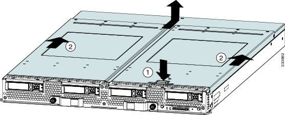 |
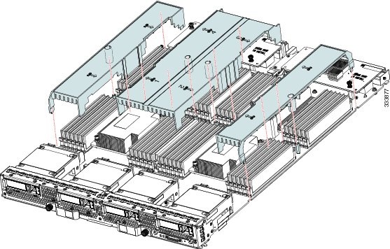
Air Baffles
The air baffles shown below ship with this server; they direct and improve air flow for the server components. No tools are necessary to install them. Place them over the DIMMs and align them to the standoffs.
Caution |
Be sure that the tabs on the baffles are set in the slots provided on the motherboard; otherwise, it may be difficult to replace the server cover or damage to the motherboard might occur. |
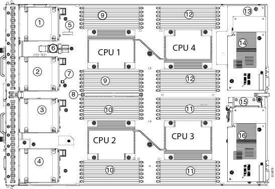
Internal Components
|
1 |
Hard drive bay 1 |
2 |
Drive bay 2 |
|
3 |
Hard drive bay 3 |
4 |
Drive bay 4 |
|
5 |
CMOS battery |
6 |
Internal USB connector Cisco UCS-USBFLSH-S-4GB= is recommended, but if you use another USB drive it must be no wider than 0.8 inches (20 mm), and no more than 1.345 inches (34 mm) long in order to provide needed clearances to install or remove the USB drive. Third-party USB flash memory is allowed but not subject to support by Cisco and is at the user’s risk. |
|
7 |
Diagnostics Button |
8 |
Transferable Flash-backed Write Cache Module (TFM) for flash-backed write cache The flash-backed write cache feature is not supported at the initial server release. |
|
9 |
DIMM slots for CPU 1 |
10 |
DIMM slots for CPU 2 |
|
11 |
DIMM slots for CPU 3 |
12 |
DIMM slots for CPU 4 |
|
13 |
mLOM card This slot is shown in Cisco UCS Manager as “Adapter 1” but the BIOS lists it as “mLOM.” The VIC 1240 is a type of adapter with a specific footprint that can only be used in this slot. |
14 |
Adapter card This slot is shown in Cisco UCS Manager as “Adapter 2,” but is shown in the BIOS as “Mezz 1.” Mixing adapter types is supported. |
|
15 |
Supercap for flash-backed write cache The flash-backed write cache feature is not supported at the initial server release. |
16 |
Adapter card This slot is shown in Cisco UCS Manager as “Adapter 3,” but it is shown in the BIOS as “Mezz 2.” Mixing adapter types is supported. |
Note |
|
Diagnostics Button and LEDs
At blade start-up, POST diagnostics test the CPUs, DIMMs, HDDs, and rear mezzanine modules, and any failure notifications are sent to Cisco UCS Manager. You can view these notifications in the Cisco UCS Manager System Error Log or in the output of the show tech-support command. If errors are found, an amber diagnostic LED also lights up next to the failed component. During run time, the blade BIOS and component drivers monitor for hardware faults and will light up the amber diagnostic LED as needed.
LED states are saved, and if you remove the blade from the chassis the LED values will persist for up to 10 minutes. Pressing the LED diagnostics button on the motherboard causes the LEDs that currently show a component fault to light for up to 30 seconds for easier component identification. LED fault values are reset when the blade is reinserted into the chassis and booted, and the process begins from its start.
If DIMM insertion errors are detected, they may cause the blade discovery process to fail and errors will be reported in the server POST information, which is viewable using the UCS Manager GUI or CLI. DIMMs must be populated according to specific rules. The rules depend on the blade server model. Refer to the documentation for a specific blade server for those rules.
Faults on the DIMMs or rear mezzanine modules also cause the server health LED to light solid amber for minor error conditions or blinking amber for critical error conditions.
Working Inside the Blade Server
Installing a CMOS Battery
All Cisco UCS blade servers use a CR2032 battery to preserve BIOS settings while the server is not installed in a powered-on chassis. Cisco supports the industry standard CR2032 battery that is available at most electronics stores.
 Warning |
There is danger of explosion if the battery is replaced incorrectly. Replace the battery only with the same or equivalent type recommended by the manufacturer. Dispose of used batteries according to the manufacturer’s instructions. |
To install or replace the battery, follow these steps:
SUMMARY STEPS
- Remove the existing battery:
- Install the replacement battery:
DETAILED STEPS
|
Step 1 |
Remove the existing battery:
|
|
Step 2 |
Install the replacement battery: |
Removing a CPU and Heat Sink
You will use these procedures to move a CPU from one server to another, to replace a faulty CPU, or to upgrade from one CPU to another.
Caution |
The Pick-and-Place tools used in this procedure are required to prevent damage to the contact pins between the motherboard and the CPU. Do not attempt this procedure without the required tools. If you do not have the tool, you can order a spare.
|
Procedure
|
Step 1 |
Unscrew the four captive screws securing the heat sink to the motherboard. Loosen one screw by a quarter turn, then move to the next screw. Continue loosening until the heat sink can be lifted off. |
||||
|
Step 2 |
Remove the heat sink. Remove the existing thermal compound from the bottom of the heat sink using the cleaning kit included with each CPU option kit. Follow the instructions on the two bottles of cleaning solvent. |
||||
|
Step 3 |
Unhook the first socket hook, which has the following icon: |
||||
|
Step 4 |
Unhook the second socket hook, which has the following icon: |
||||
|
Step 5 |
Open the socket latch.  |
||||
|
Step 6 |
Press the central button on the CPU Pick-and-Place tool to release the catch. |
||||
|
Step 7 |
Remove an old CPU as follows:

|
Installing a New CPU and Heat Sink
Before installing a new CPU in a server, verify the following:
-
The CPU is supported for that given server model. Refer to the Specification Sheet for this server to see the list of supported CPUs. The Specification Sheets are available at this URL: http://www.cisco.com/c/en/us/products/servers-unified-computing/ucs-b-series-blade-servers/datasheet-listing.html
-
A BIOS update is available and installed that supports the CPU and the given server configuration.
-
If the server will be managed by Cisco UCS Manager, the service profile for this server in Cisco UCS Manager will recognize and allow the new CPU.
Caution |
The Pick-and-Place tools used in this procedure are required to prevent damage to the contact pins between the motherboard and the CPU. Do not attempt this procedure without the required tools. If you do not have the tool, you can order a spare.
|
Procedure
|
Step 1 |
To install a CPU in an empty socket, remove the protective cap that is intended to prevent bent or touched contact pins. The pick and pull cap tool provided can be used in a manner similar to a pair of tweezers. Grasp the protective cap and pivot as shown. 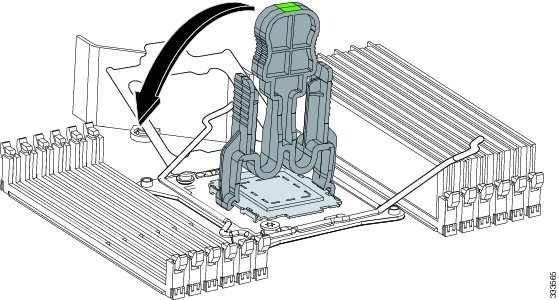 |
||||
|
Step 2 |
Release the catch on the pick and pull tool by pressing the handle/button. |
||||
|
Step 3 |
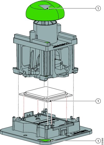
Remove the new CPU from the packaging, and load it into the pick and place tool as follows:
|
||||
|
Step 4 |
Place the CPU and tool on the CPU socket with the registration marks aligned as shown. |
||||
|
Step 5 |
Press the button/handle on the pick and place tool to release the CPU into the socket.
|
||||
|
Step 6 |
Close the socket latch. See callout 1 in the following figure. |
||||
|
Step 7 |
Secure the first hook, which has the following icon: |
||||
|
Step 8 |
Secure the second hook, which has the following icon: 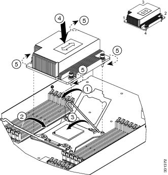 |
||||
|
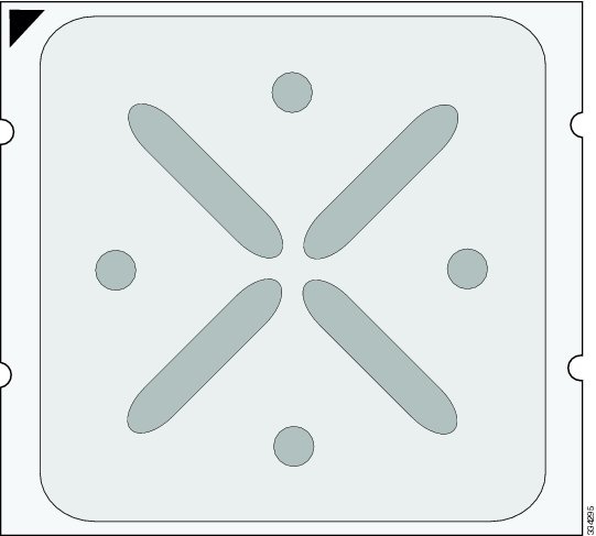
Step 9 |
Using the syringe of thermal grease provided with replacement CPUs and servers, add 2 cubic centimeters of thermal grease to the top of the CPU where it will contact the heat sink. Use the pattern shown. This should require half the contents of the syringe.
 |
||||
|
Step 10 |
Replace the heat sink. See callout 4.
|
||||
|
Step 11 |
Secure the heat sink to the motherboard by tightening the four captive screws a quarter turn at a time in an X pattern as shown in the upper right. |
Installing Memory
To install a DIMM into the blade server, follow these steps:
SUMMARY STEPS
- Press the DIMM into its slot evenly on both ends until it clicks into place.
- Press the DIMM connector latches inward slightly to seat them fully.
DETAILED STEPS
|
Step 1 |
Press the DIMM into its slot evenly on both ends until it clicks into place. DIMMs are keyed. If a gentle force is not sufficient, make sure the notch on the DIMM is correctly aligned.
|
||
|
Step 2 |
Press the DIMM connector latches inward slightly to seat them fully. |
Supported DIMMs
The DIMMs supported in this blade server are constantly being updated. A list of currently supported and available DIMMs is in the Cisco UCS B420 M3 specification sheet: http://www.cisco.com/c/dam/en/us/products/collateral/servers-unified-computing/ucs-b-series-blade-servers/b420m3_specsheet.pdf.
Do not use any memory DIMMs other than those listed in the specification sheet. Doing so may irreparably damage the server and require an RMA and down time.
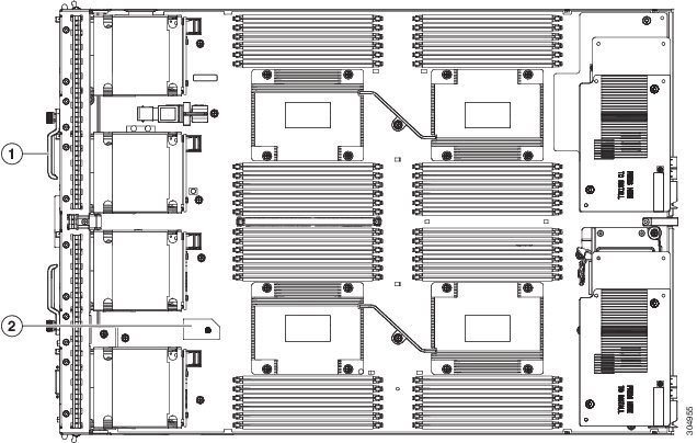
Memory Arrangement
The Cisco UCS B420 high-performance blade server contains 48 slots for installing DIMMs—12 for each CPU. Each CPU has 12 DIMM slots spread over 4 channels. This blade server needs at least one DIMM attached to all populated CPUs. DIMMs installed in slots for an absent CPU will not be recognized. For optimal performance, distribute DIMMs evenly across all CPUs. DIMM connector latches are color coded blue, black, and white, and the DIMMs must be installed in that order.
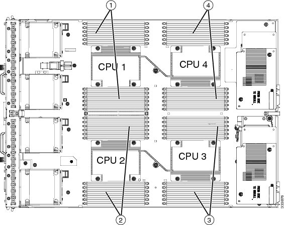
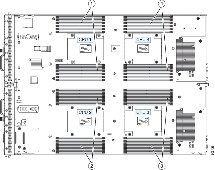
|
1 |
DIMMs for CPU 1 |
3 |
DIMMs for CPU 3 |
|
2 |
DIMMs for CPU 2 |
4 |
DIMMs for CPU 4 |
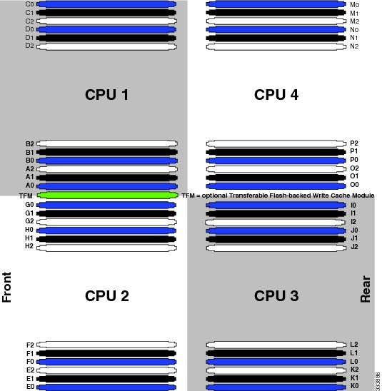
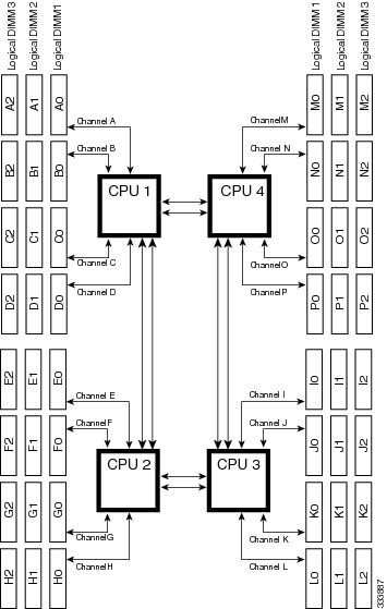
Channels
Each CPU has 4 channels, consisting of 3 DIMMs. Each channel is identified by a letter. Each channel member is identified by numbers, 0, 1 or 2.
The DIMM slots are contiguous to their associated CPU. When installing DIMMs, you must add them in the configurations shown in the following table.
|
DIMMs per CPU |
Populate CPU 1 Slots |
Populate CPU 2 Slots |
Populate CPU 3 Slots |
Populate CPU 4 Slots |
Color Coding |
|---|---|---|---|---|---|
|
1 |
A0 |
E0 |
I0 |
M0 |
Blue |
|
2 |
A0, B0 |
E0, F0 |
I0, J0 |
M0, N0 |
Blue |
|
3 |
A0, B0, C0 |
E0, F0, G0 |
I0, J0, K0 |
M0, N0, O0 |
Blue |
|
4 |
A0, B0, C0, D0 |
E0, F0, G0, H0 |
I0, J0, K0, L0 |
M0, N0, O0, P0 |
Blue |
|
5 |
Not recommended for performance reasons. |
||||
|
6 |
A0, B0, C0, A1, B1, C1 |
E0, F0, G0, E1, F1, G1 |
I0, J0, K0, I1, J1, K1 |
M0, N0, O0, M1, N1, O1 |
Blue, Black |
|
7 |
Not recommended for performance reasons. |
||||
|
8 |
A0, B0, C0, D0, A1, B1, C1, D1 |
E0, F0, G0, H0, E1, F1, G1, H1 |
I0, J0, K0, L0, I1, J1, K1, L1 |
M0, N0, O0, P0, M1, N1, O1, P1 |
Blue, Black |
|
9 |
A0, B0, C0, A1, B1, C1, A2, B2, C2 |
E0, F0, G0, E1, F1, G1, E2, F2, G2 |
I0, J0, K0, I1, J1, K1, I2, J2, K2 |
M0, N0, O0, M1, N1, O1, M2, N2, O2 |
Blue, Black White |
|
10 |
Not recommended for performance reasons. |
||||
|
11 |
Not recommended for performance reasons. |
||||
|
12 |
A0, B0, C0, D0, A1, B1, C1, D1, A2, B2, C2, D2 |
E0, F0, G0, H0, E1, F1, G1, H1, E2, F2, G2, H2 |
I0, J0, K0, L0, I1, J1, K1, L1, I2, J2, K2, L2 |
M0, N0, O0, P0, M1, N1, O1, P1, M2, N2, O2, P2 |
Blue, Black White |
Memory Performance
When configuring your server, consider the following:
-
DIMMs within the blade can be of different speeds, but all DIMMs will run at the speed of the DIMM with the lowest speed.
-
No mixing of DIMM type (LRDIMM, RDIMM, TSV-RDIMM) is allowed.
-
Your selected CPU(s) can have some affect on performance. CPUs used must be of the same type.
-
Mixing DIMM ranks and densities can lower performance.
-
Unevenly populating DIMMs between CPUs can lower performance.
Bandwidth and Performance
You can achieve maximum bandwidth, performance, and system memory by using the following configuration:
-
DDR3, 1600 millions of transfers per second (MT/s) across four Channels
-
12 DIMMs per CPU (48 DIMMs total)
-
Maximum capacity of 1536 GB (using 32-GB DIMMs)
Performance is less than optimal if the following memory configurations are used:
-
Mixing DIMM sizes and densities
-
Unevenly populating DIMMs between CPUs
Depending on the application needed, performance loss might or might not be noticeable or measurable.
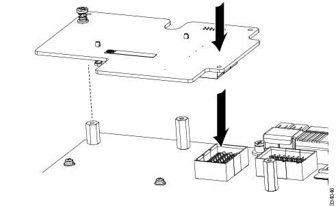
Installing a Virtual Interface Card Adapter
Note |
You must remove the adapter card to service it. |
To install a Cisco VIC 1340 or VIC 1240 in the blade server, follow these steps:
SUMMARY STEPS
- Position the VIC board connector above the motherboard connector and align the captive screw to the standoff post on the motherboard.
- Firmly press the VIC board connector into the motherboard connector.
- Tighten the captive screw.
DETAILED STEPS
|
Step 1 |
Position the VIC board connector above the motherboard connector and align the captive screw to the standoff post on the motherboard. |
||
|
Step 2 |
Firmly press the VIC board connector into the motherboard connector. |
||
|
Step 3 |
Tighten the captive screw.
 |
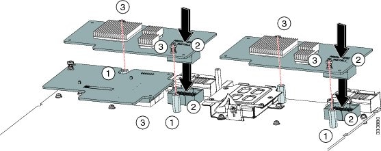
Installing an Adapter Card
All the supported mezzanine cards have a common installation process. These cards are updated frequently. Currently supported cards and the available models for this server are listed in the specification sheets at this URL: http://www.cisco.com/c/en/us/products/servers-unified-computing/ucs-b-series-blade-servers/datasheet-listing.html
If you are switching from one type of adapter card to another, before you physically perform the switch make sure that you download the latest device drivers and load them into the server’s operating system. For more information, see the firmware management chapter of one of the Cisco UCS Manager software configuration guides.
Adapter cards can be installed in either slot 1 or slot 2; they can be of the same type or a mixed configuration.
Note |
Cisco UCS Manager will recognize adapters in these slots as “Adapter 2” and “Adapter 3,” and counts the mLOM as being “Adapter 1.“ This does not match the markings on the motherboard. |
SUMMARY STEPS
- Position the adapter board connector above the motherboard connector and align the two adapter captive screws to the standoff posts (see callout 1) on the motherboard.
- Firmly press the adapter connector into the motherboard connector (see callout 2).
- Tighten the two captive screws (see callout 3).
DETAILED STEPS
|
Step 1 |
Position the adapter board connector above the motherboard connector and align the two adapter captive screws to the standoff posts (see callout 1) on the motherboard. |
||
|
Step 2 |
Firmly press the adapter connector into the motherboard connector (see callout 2). |
||
|
Step 3 |
Tighten the two captive screws (see callout 3).
 |
Installing the Flash-Backed Write Cache and Supercap
The Flash-backed Write Cache (FBWC) is an intelligent backup solution that protects disk write cache data during a long term power loss on the RAID controller. It has two components, the TFM memory and the Supercap module, which provides emergency power. The TFM installs into a dedicated slot, but the installation steps are identical to installing a DIMM. The flash-backed write cache feature and its components are not supported at the initial server release.
Verify whether replacement is required by using the show raid-battery detail command in the CLI.
To install the Supercap module, follow these steps:
SUMMARY STEPS
- Using Cisco UCS Manager, perform a graceful shutdown of the server. Without a graceful shutdown, data can be permanently lost.
- Remove the server from the chassis.
- Remove the top cover from the server.
- Remove the adapter in slot 2.
- With a No.1 Phillips screwdriver, remove the four screws holding the top plate of the Supercap’s enclosure.
- Angle the top plate up and remove the tabs from the slots at the rear. Set the plate aside.
- Press the clip at the end of the Supercap’s wires into the clip attached to the enclosure.
- Place the Supercap inside the enclosure.
- Slide the tabs on the top plate into the slots at the rear of the Supercap enclosure.
- With a No.1 Phillips screwdriver, replace the four screws and attach the top plate to the enclosure as shown below.
- Replace the adapter, top cover, and the server in the chassis. Cisco UCS Manager reestablishes management of the server and the service profile.
DETAILED STEPS
|
Step 1 |
Using Cisco UCS Manager, perform a graceful shutdown of the server. Without a graceful shutdown, data can be permanently lost. |
|
Step 2 |
Remove the server from the chassis. |
|
Step 3 |
Remove the top cover from the server. |
|
Step 4 |
Remove the adapter in slot 2. |
|
Step 5 |
With a No.1 Phillips screwdriver, remove the four screws holding the top plate of the Supercap’s enclosure. |
|
Step 6 |
Angle the top plate up and remove the tabs from the slots at the rear. Set the plate aside. |
|
Step 7 |
Press the clip at the end of the Supercap’s wires into the clip attached to the enclosure. |
|
Step 8 |
Place the Supercap inside the enclosure. |
|
Step 9 |
Slide the tabs on the top plate into the slots at the rear of the Supercap enclosure. |
|
Step 10 |
With a No.1 Phillips screwdriver, replace the four screws and attach the top plate to the enclosure as shown below. |
|
Step 11 |
Replace the adapter, top cover, and the server in the chassis. Cisco UCS Manager reestablishes management of the server and the service profile. 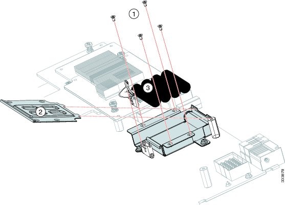 |
Installing and Enabling a Trusted Platform Module
The Trusted Platform Module (TPM) is a component that can securely store artifacts used to authenticate the server. These artifacts can include passwords, certificates, or encryption keys. A TPM can also be used to store platform measurements that help ensure that the platform remains trustworthy. Authentication (ensuring that the platform can prove that it is what it claims to be) and attestation (a process helping to prove that a platform is trustworthy and has not been breached) are necessary steps to ensure safer computing in all environments. It is a requirement for the Intel Trusted Execution Technology (TXT) security feature, which must be enabled in the BIOS settings for a server equipped with a TPM.
Note |
TPM installation is supported after-factory. However, a TPM installs with a one-way screw and cannot be replaced or moved to another server. If a server with a TPM is returned, the replacement server must be ordered with a new TPM. |
SUMMARY STEPS
- Install the TPM hardware.
- Enable TPM Support in the BIOS.
- Enable TPM State in the BIOS.
- Verify that TPM Support and TPM State are enabled.
- Enable the Intel TXT feature in the BIOS.
DETAILED STEPS
|
Step 1 |
Install the TPM hardware.
|
||||
|
Step 2 |
Enable TPM Support in the BIOS. |
||||
|
Step 3 |
Enable TPM State in the BIOS.
|
||||
|
Step 4 |
Verify that TPM Support and TPM State are enabled.
|
||||
|
Step 5 |
Enable the Intel TXT feature in the BIOS. |
Server Troubleshooting
For general troubleshooting information, see the Cisco UCS Manager Troubleshooting Reference Guide.
Server Configuration
Cisco Intersight Managed Mode
Cisco UCS blade servers can be configured and managed using the Cisco Intersight management platform in Intersight Managed Mode (Cisco Intersight Managed Mode). For details, see the Cisco Intersight Managed Mode Configuration Guide, which is available at the following URL: https://www.cisco.com/c/en/us/td/docs/unified_computing/Intersight/b_Intersight_Managed_Mode_Configuration_Guide.html
Cisco UCS Manager
Cisco UCS blade servers can be configured and managed using Cisco UCS Manager. For details, see the Configuration Guide for the version of Cisco UCS Manager that you are using. The configuration guides are available at the following URL: http://www.cisco.com/en/US/products/ps10281/products_installation_and_configuration_guides_list.html
Physical Specifications for the Cisco UCS B420 M3
|
Specification |
Value |
|---|---|
|
Height |
1.95 inches (50 mm) |
|
Width |
16.50 inches (419.1 mm) |
|
Depth |
24.4 inches (620 mm) |
|
Weight |
34.5 lbs (15.65 kg) The system weight listed here is an estimate for a fully configured system and will vary depending on peripheral devices installed. |
 Feedback