Introduction
This document provides installation information for the Cisco UCS E-Series M6 Servers. It includes the following sections:
New and Changed Information
|
Feature |
Description |
Changed in Software Release |
Updated Sections |
|---|---|---|---|
|
UCS E-Series M6 Servers |
New server - E1100D-M6 - introduced |
1.0 |
New Hardware Installation Guide document |
Overview
The Cisco UCS E-Series M6 Server is a power-efficient blade server that is housed within the Cisco Catalyst 8300 Series Edge platforms. This server provides a general-purpose compute platform for branch-office applications deployed either as bare-metal on operating systems, such as Linux, or as virtual machines on hypervisors, such as VMware vSphere Hypervisor.
The Cisco UCS E-Series M6 Server is purpose-built with powerful Intel Icelake-D processors for general-purpose compute. It comes in the double-wide form factor, and fits into two SM slots.
Hardware Requirements
Cisco UCS E-Series M6—Double-wide E-Series M6 Servers specifications:
-
10-cores CPU
-
3.0-GHz clock speed
The Cisco UCS E-Series M6 Servers can be installed in the following platforms:
-
Cisco C8300-2N2S-6T
-
Cisco C8300-2N2S-4T2X
Hardware Information for the Cisco UCS E-Series M6 Servers
|
Feature |
UCS E-Series M6 Server |
|---|---|
|
Form Factor |
Double-wide Service Module |
|
CPU |
Intel Icelake-D Processor |
|
CPU Cores and CPU Clock Speed |
10-Cores with 3.0-GHz Clock Speed |
|
Memory DIMM Slots |
4 Slots |
|
RAM |
16 to 128 GB Supports DDR4 2667-MHz DIMM1.2 V, 16 GB, and 32 GB |
|
RAID |
RAID 0, RAID 1 and RAID 5 |
|
Storage Type1 |
SATA SSD, NVMe Drive, and USB 3.0 Type C Connector |
|
Storage Capacity2 |
480 GB to 16 TB |
|
Internal Network Interface |
2 10-Gigabit Ethernet Interfaces |
|
External Interfaces |
1 USB 3.0 Type C Connector 1 RJ-45 Gigabit Ethernet Connector 2 SFP+ 10 Gigabit Ethernet Connectors 1 RJ-45 Management Ethernet Port 1 KVM Connector (1 VGA port, 2-port USB 2.0 connector, 1 Serial DB9 port) |
|
Router Platforms |
C8300-2N2S-4T2X C8300-2N2S-6T |
|
Maximum Number of UCS E-Series M6 Servers per Router3 |
C8300-2N2S-4T2X - 1 E-Series M6 Server C8300-2N2S-6T - 1 E-Series M6 Server |
Supported Transceivers
|
SFP |
Description |
|---|---|
|
SFP-10G-SR |
10GBase-SR SFP+Module for MMF |
|
SFP-10G-LR |
10GBase-LR SFP+Module for SMF |
|
SFP-10G-SR-S |
10GBASE-SR SFP + Module for MMF S-Class |
|
SFP-10G-LR-S |
10GBASE-LR SFP + Module for SMF S-Class |
|
GLC-SX-MMD |
1000BASE-SX short-wavelength, with DOM |
|
GLC-LH-SMD |
1000BASE-LX/LH long-wavelength, with DOM |
|
SFP-H10GB-ACU7M |
10GBASE-CU SFP+ cable 7 meter, active |
|
SFP-H10GB-ACU10M |
10GBASE-CU SFP+ cable 10 meter, active |
Recommended Safety Practices
This section describes recommended practices for safe and effective installation of the hardware, and includes the following topics:
Safety Recommendations
To prevent hazardous conditions, follow these safety recommendations while working with this equipment:
-
Keep tools away from walk areas where you or others could fall over them.
-
Do not wear loose clothing around the router. Fasten your tie or scarf and roll up your sleeves to prevent clothing from being caught in the chassis.
-
Wear safety glasses when working under any conditions that might be hazardous to your eyes.
-
Locate the emergency power-off switch in the room before you start working. If an electrical accident occurs, shut the power off.
-
Before working on the router, turn off the power and unplug the power cord.
-
Disconnect all power sources before doing the following:
-
Installing or removing a router chassis
-
Working near power supplies
-
-
Do not work alone if potentially hazardous conditions exist.
-
Always check that power is disconnected from a circuit.
-
Remove possible hazards from your work area, such as damp floors, ungrounded power extension cables, or missing safety grounds.
-
If an electrical accident occurs, proceed as follows:
-
Use caution; do not become a victim yourself.
-
Turn off power to the room using the emergency power-off switch.
-
If possible, send another person to get medical aid. Otherwise, determine the condition of the victim and then call for help.
-
Determine if the person needs rescue breathing or external cardiac compressions; then take appropriate action.
-
Preventing Electrostatic Discharge Damage
Electrostatic discharge can damage equipment and impair electrical circuitry. Electrostatic discharge occurs when electronic printed circuit cards, such as those used in Cisco service modules and network modules, are improperly handled and can result in complete or intermittent equipment failure. Always observe the following electrostatic discharge damage (ESD) prevention procedures when installing, removing, and replacing the Cisco UCS E-Series M6 Servers:
-
Make sure that the router chassis is electrically connected to earth ground.
-
Wear an ESD-preventive wrist strap, and make sure that it makes good contact with your skin.
-
Connect the wrist strap clip to an unpainted portion of the chassis frame to channel unwanted ESD voltages to ground.
-
If no wrist strap is available, ground yourself by touching the metal part of the router chassis.
 Caution |
The wrist strap and clip must be used correctly to ensure proper ESD protection. Periodically confirm that the resistance value of the ESD-preventive wrist strap is between 1 and 10 megohms (Mohm). |
Maintenance Guidelines
The following maintenance guidelines apply to Cisco UCS E-Series M6 Servers:
-
Keep the router chassis area clear and dust-free during and after installation.
-
If you remove the chassis cover for any reason, store it in a safe place.
-
Do not perform any action that creates a hazard to people or makes equipment unsafe.
-
Keep walk areas clear to prevent falls or damage to equipment.
-
Follow installation and maintenance procedures as documented by Cisco Systems, Inc.
Safety Warnings
The following safety warning statements apply to all hardware procedures involving the Cisco UCS E-Series M6 Servers. Translations of these warnings are available in the Cisco Network Modules and Interface Cards Regulatory Compliance and Safety Information document at:
http://www.cisco.com/en/US/docs/routers/access/interfaces/rcsi/IOHrcsi.html
 Warning |
Statement 1071—Warning Definition IMPORTANT SAFETY INSTRUCTIONS Before you work on any equipment, be aware of the hazards involved with electrical circuitry and be familiar with standard practices for preventing accidents. Read the installation instructions before using, installing, or connecting the system to the power source. Use the statement number provided at the end of each warning statement to locate its translation in the translated safety warnings for this device. SAVE THESE INSTRUCTIONS  |
Warning |
Statement 1074—Comply with Local and National Electrical Codes To reduce risk of electric shock or fire, installation of the equipment must comply with local and national electrical codes. |
Warning |
Statement 1024—Ground Conductor This equipment must be grounded. To reduce the risk of electric shock, never defeat the ground conductor or operate the equipment in the absence of a suitably installed ground conductor. Contact the appropriate electrical inspection authority or an electrician if you are uncertain that suitable grounding is available. |
Warning |
Statement 1029—Blank Faceplates and Cover Panels Blank faceplates and cover panels serve three important functions: they reduce the risk of electric shock and fire, they contain electromagnetic interference (EMI) that might disrupt other equipment, and they direct the flow of cooling air through the chassis. Do not operate the system unless all cards, faceplates, front covers, and rear covers are in place. |
Warning |
Statement 1046—Installing or Replacing the Unit To reduce risk of electric shock, when installing or replacing the unit, the ground connection must always be made first and disconnected last. If your unit has modules, secure them with the provided screws. |
Warning |
Statement 1008—Class 1 Laser Product This product is a Class 1 laser product. |
Warning |
Statement 1056—Unterminated Fiber Cable Invisible laser radiation may be emitted from the end of the unterminated fiber cable or connector. Do not view directly with optical instruments. Viewing the laser output with certain optical instruments, for example, eye loupes, magnifiers, and microscopes, within a distance of 100 mm, may pose an eye hazard. |
Warning |
Statement 9001—Product Disposal Ultimate disposal of this product should be handled according to all national laws and regulations. |
Types of Cisco UCS E-Series M6 Servers
Cisco UCS E-Series M6 Servers are available in the following form factors:
-
Double-wide E-Series M6 Servers: UCS-E1100D-M6
Cisco UCS E-Series M6 Servers
Back Panel and Internal Components
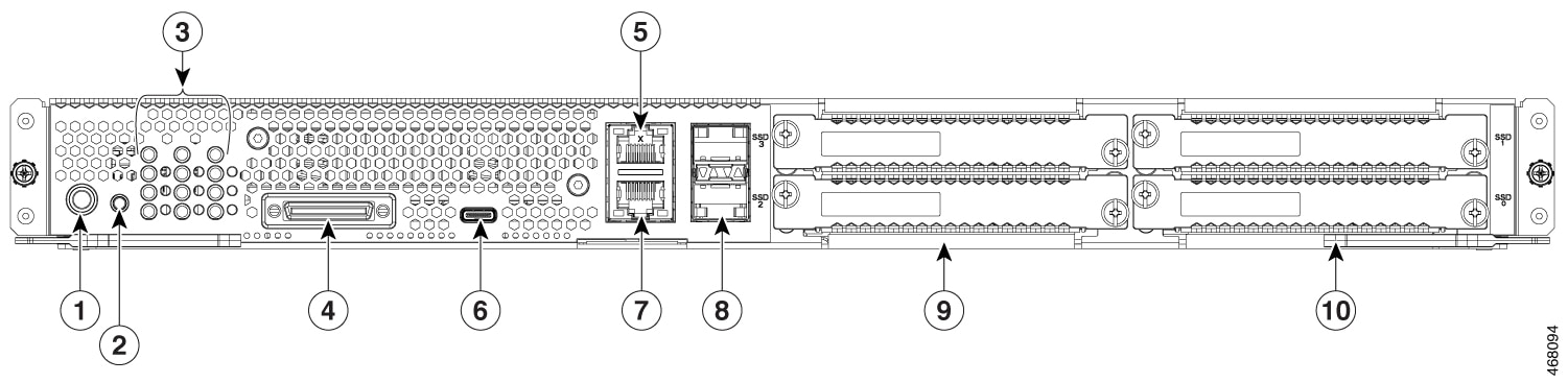
|
1 |
Power Button |
2 |
Reset Switch |
|
3 |
LEDs |
4 |
KVM/ Console Port |
|
5 |
Management Port |
6 |
USB C-Type Port 0 |
|
7 |
Gigabit Ethernet Port 2 |
8 |
SFP+ Ports 3 and 4 |
|
9 |
SSD2 and SSD3 |
10 |
SSD0 and SSD1 |
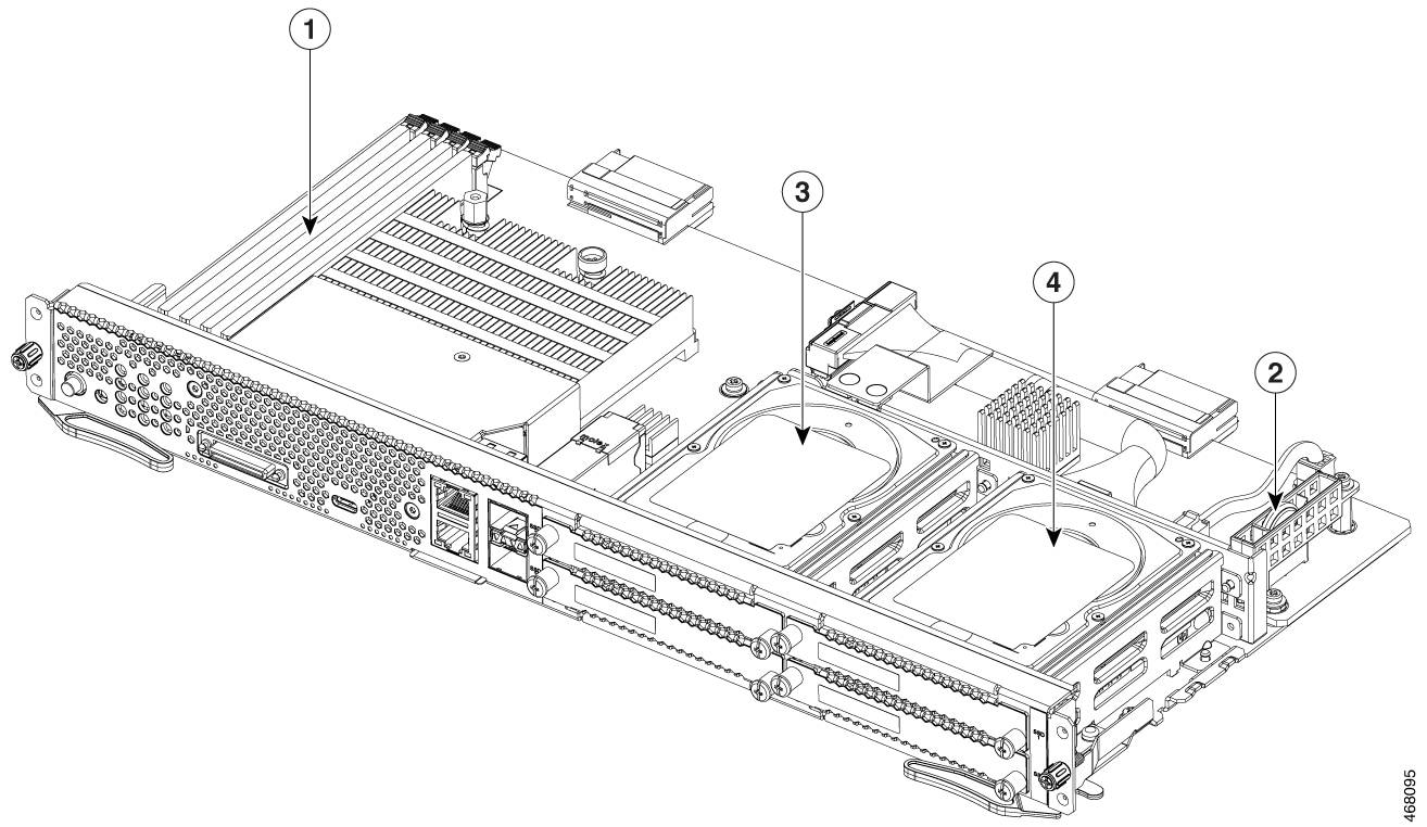
|
1 |
Memory DIMM slots |
2 |
CMOS battery (resides inside the battery protector) |
|
3 |
SSD2 and SSD3 |
4 |
SSD0 and SSD1 |
UCS E-Series M6 Server LEDs
The following table lists the LEDs on the Cisco UCS E-Series M6 Server, and describes the LED colors and states.
|
LED |
Color |
State |
|---|---|---|
|
ACT0 |
Green |
Status of the hard drive activity:
|
|
FLT0 |
Amber |
Fault is detected on the hard drive. |
|
ACT1 |
Green |
Status of the hard drive activity:
|
|
FLT1 |
Amber |
Fault is detected on the hard drive. |
|
ACT2 |
Green |
Status of the hard drive activity:
|
|
FLT2 |
Amber |
Fault is detected on the hard drive. |
|
ACT3 |
Green |
Status of the hard drive activity:
|
|
FLT3 |
Amber |
Fault is detected on the hard drive. |
|
STS |
Green |
Operation is normal. |
|
Amber |
Fault is detected on the processor. |
|
|
SYS |
Green |
System is active. |
|
CIMC |
Green |
Solid when the CIMC is operating normally. |
|
Amber |
CIMC is in the process of booting up. |
|
|
EN |
Green |
The module is powered on and is functioning correctly. |
|
Amber |
The module has some failure or is not ready. |
|
|
Power |
Green |
|
|
Amber |
|
|
|
GE Port LEDs |
Green |
Left LED shows the speed of the Ethernet cable:
|
|
Green |
Right LED shows whether the link is established.
|
|
|
SFP+ Port LEDs |
Green |
Left LED shows whether the link is established:
|
|
Green |
Right LED shows whether the port is enabled:
|
|
|
Amber |
Right LED shows whether the port is enabled:
|
Basic Workflow for Installing the UCS E-Series M6 Server in the SM Slot
Procedure
| Command or Action | Purpose | |
|---|---|---|
|
Step 1 |
Gather the required tools and equipment. |
|
|
Step 2 |
Unpack and inspect the module. |
|
|
Step 3 |
Remove the blank faceplates from the SM slots that you want to use. |
|
|
Step 4 |
Depending on the type of server that you want to install, either remove or install the slot divider. |
|
|
Step 5 |
Install the E-Series M6 Server into the router. |
|
|
Step 6 |
Verify the E-Series M6 Server installation. |
Tools and Equipment Required for Installation
-
Number-1 Phillips screwdriver or a small flat-blade screwdriver
-
ESD-preventive wrist strap
-
Tape to secure DC circuit breaker handle—Applicable for routers that use DC power
Unpacking and Inspecting the Server
Procedure
|
Step 1 |
Remove the module from its cardboard container and save all packaging material. |
||
|
Step 2 |
Compare the shipment to the equipment list provided by your customer service representative. Verify that you have all items. |
||
|
Step 3 |
Check for damage and report any discrepancies or damage to your customer service representative. Have the following information ready:
|
Removing the Blank Faceplate from the Router’s SM Slot
Warning |
Statement 1029—Blank Faceplates and Cover Panels Blank faceplates and cover panels serve three important functions: they reduce the risk of electric shock and fire, they contain electromagnetic interference (EMI) that might disrupt other equipment, and they direct the flow of cooling air through the chassis. Do not operate the system unless all cards, faceplates, front covers, and rear covers are in place. |
Before You Begin
Make sure that you connect the wrist-strap clip to an unpainted portion of the chassis frame to channel unwanted ESD voltages to ground.
Procedure
|
Step 1 |
Using either a number-1 Phillips screwdriver or a small flat-blade screwdriver, unscrew the captive screws and remove both blank faceplates from the chassis slot. 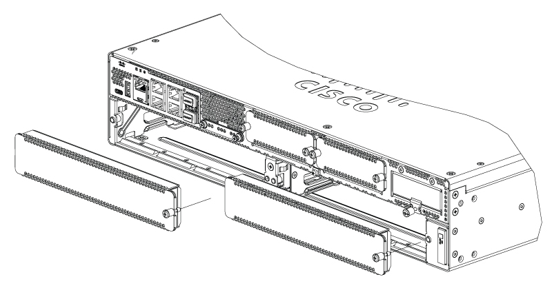
|
|
Step 2 |
Save the blank faceplates for future use. |
What to do next
Prepare the router slot for UCS E-Series M6 Server installation. See the section Preparing the Router’s SM Slot for UCS E-Series M6 Server Installation.
Preparing the Router’s SM Slot for UCS E-Series M6 Server Installation
The Cisco Catalyst 8300 Series Edge routers have a flexible SM slot to support various Cisco server modules. Before installing the UCS E-Series M6 Server into the router, prepare the router’s SM slot for the server’s particular form factor.
By default, a slot divider is preinstalled in the Cisco Catalyst 8300 Series Edge router. The UCS E-Series M6 server is a double-wide module, so you must remove the slot divider from the router.
See the section Removing the Slot Divider for UCS E-Series M6 Server Installation for more information.
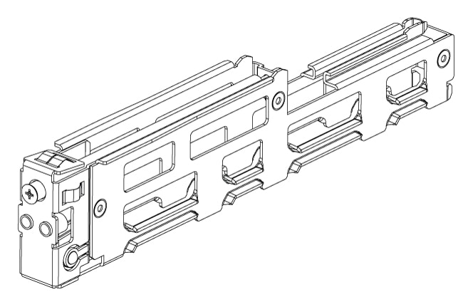
Removing the Slot Divider for UCS E-Series M6 Server Installation
To install the UCS E-Series M6 server in the router's SM slot, you must remove the slot divider. Use this procedure to remove the slot dividers from the SM slot.
Before You Begin
Make sure that you connect the wrist-strap clip to an unpainted portion of the chassis frame to channel unwanted ESD voltages to ground.
Procedure
|
Step 1 |
Remove any installed service modules, blank faceplates, and slot adapters from the router slot that you plan to use. |
|
Step 2 |
Loosen the retention screw on the front of the slot divider; do not remove the screw completely from the slot divider. |
|
Step 3 |
Pull the slot divider straight out of the module slot. 
|
What to do next
Install the UCS E-Series M6 server into the router. See the section Installing the UCS E-Series M6 Server into the Router.
Installing the UCS E-Series M6 Server into the Router
The UCS E-Series M6 Server can be installed either before or after mounting the router, whichever is more convenient.
Caution |
To prevent damage to the server, handle the server by the chassis or frame. |
Before You Begin
Verify that you have done the following:
-
Removed the blank faceplates from the slots that you intend to use. See the section Removing the Blank Faceplate from the Router’s SM Slot.
-
Saved the blank faceplates for future use.
-
Prepared the slot for the module form factor that you are installing. See the section Preparing the Router’s SM Slot for UCS E-Series M6 Server Installation .
-
Connected a wrist-strap clip to an unpainted portion of the chassis frame to channel unwanted ESD voltages to ground.
Procedure
|
Step 1 |
Turn off the electrical power to the router. Leave the power cable plugged in to the channel ESD voltages to ground.
|
||||||||||
|
Step 2 |
With the latches in the open position, align the module with the guides in the chassis walls, and slide the module gently into the slot. See the following figure: 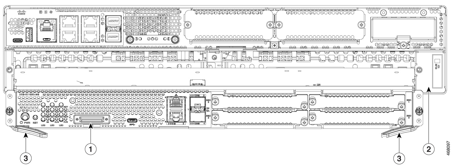
|
||||||||||
|
Step 3 |
Push the module into place until you feel the module seat securely into the connector on the router backplane, using the side latches to engage the module into the router. The module faceplate should contact the chassis face. |
||||||||||
|
Step 4 |
Using a number-1 Phillips or flat-blade screwdriver, tighten the captive mounting screws on the module faceplate. |
What to do next
-
Check that the IOS-XE image installed in the router is compatible with the E-Series M6 server.

Note
The UCS E-Series M6 servers are supported from Cisco IOS-XE 17.11.1a onwards. To upgrade the IOS-XE image on your Catalyst 8300 Series Edge platforms, obtain the package (image) from https://software.cisco.com/download/home, and follow the instructions in chapter Installing the Software in the Cisco Catalyst 8300 and Catalyst 8200 Series Edge Platforms Software Configuration Guide.
-
Check the BIOS and CIMC images installed on the server.
Note
The E-Series M6 server comes with BIOS and CIMC images preinstalled. To upgrade the BIOS or CIMC image on your UCS E-Series M6 server, obtain the package (image) from https://software.cisco.com/download/home, and follow the instructions in chapter Firmware Management in the CLI Configuration Guide for UCS E-Series M6 Servers.
-
Connect the UCS E-Series M6 Server to the network and power up the router and the server.
-
Verify that the router recognizes the UCS E-Series M6 Server. See the section Verifying the UCS E-Series M6 Server Installation.
Verifying the UCS E-Series M6 Server Installation
Before You Begin
-
Install the UCS E-Series M6 Server into the router.
-
Check the router for a compatible IOS-XE image.
-
Check the BIOS and CIMC images installed on the server.
-
Power on the server.
Procedure
To verify the UCS E-Series M6 Server installation, use one of the following commands:
-
To display a high-level overview of the entire physical system, use the show platform command:
Router#show platform
Chassis type: C8300-2N2S-4T2X

Slot      Type                State                 Insert time (ago)
--------- ------------------- --------------------- -----------------
0         C8300-2N2S-4T2X     ok                    23:32:17
 0/0      4x1G-2xSFP+         ok                    23:31:16
1         C8300-2N2S-4T2X     ok                    23:32:17
 1/0      UCS-E1100D-M6       ok                    00:04:41
2         C8300-2N2S-4T2X     ok                    23:32:17
R0        C8300-2N2S-4T2X     ok, active            23:32:17
F0        C8300-2N2S-4T2X     ok, active            23:32:17
P0        PWR-CC1-650WAC      ok                    23:31:38
P1        Unknown             empty                 never
P2        C8300-FAN-2R        ok                    23:31:38

Slot      CPLD Version        Firmware Version
--------- ------------------- ---------------------------------------
0         20061845            17.3(4.1r)
1         20061845            17.3(4.1r)
2         20061845            17.3(4.1r)
R0        20061845            17.3(4.1r)
F0        20061845            17.3(4.1r)
-
To verify that the router recognizes the server, use the show hw-module subslot all oir command:
Router#show hw-module subslot all oir

Module                  Model                Operational Status
----------------------- -------------------- ------------------------
subslot 0/0             4x1G-2xSFP+          ok
subslot 1/0             UCS-E1100D-M6        ok

Router#
Online Insertion and Removal—UCS E-Series M6 Servers
Online insertion and removal (OIR) provides uninterrupted network operation, maintains routing information, and ensures session preservation on the Cisco Catalyst 8300 Series Edge platforms. You can use online insertion and removal to install or replace hardware without affecting system operations.
Inserting the UCS E-Series M6 Server in a Cisco Catalyst 8300 Series Edge Platform
A Cisco Catalyst 8300 Series Edge Platform that is up and running can detect when a UCS E-Series M6 Server is inserted in the SM slot. After the router detects the UCS E-Series M6 Server, the router software enables power to the server.
Shutting Down the UCS E-Series M6 Server Installed in a Cisco Catalyst 8300 Series Edge Platform
Procedure
| Command or Action | Purpose | |||
|---|---|---|---|---|
|
Step 1 |
enable Example: |
Enables privileged EXEC mode. Enter your password, if prompted. |
||
|
Step 2 |
ucse subslot slot 1/0 shutdown Example: |
Shuts down the UCS E-Series M6 Server gracefully.
|
||
|
Step 3 |
hw-module subslot slot /0 stop Example:Example: |
Shuts down power to the specified UCS E-Series M6 Server to prepare it for removal. When it is safe to remove the UCS E-Series M6 Server, a message is displayed as shown in the example.
|
Restarting the UCS E-Series M6 Server Installed in a Cisco Catalyst 8300 Series Edge Platform
If the oir-stop command is issued and the UCS E-Series M6 Server is not physically removed from the slot, you can restart the server with the start command. From a console terminal, issue the hw-module subslot slot /0 start command. The console displays the module’s changing state.
Router# hw-module subslot 1/0 start
Installing or Replacing Solid-State Drives on the UCS E-Series M6 Servers
The UCS E-Series M6 Servers can be ordered with one to four (1 to 4) solid-state drives (SSD) or NVMe drivers preinstalled. The UCS E-Series M6 Servers with NVMe drivers support the following Redundant Array of Independent Disks (RAID) configuration:
-
RAID 0 (data striping)—Data is stored evenly in stripe blocks across all NVMe disks in the array, providing fast throughput. There is no data redundancy, and all data is lost if any disk fails.
-
RAID 1 (disk mirroring)—Data is written to two NVMe disks, where the data in both disk drives is identical. This provides complete data redundancy if one disk fails.
-
RAID 5 (disk striping with distributed parity)—Data and parity information is striped and distributed across all disks in the array with distributed parity information. RAID 5 requires three Solid States and provides limited fault tolerance.
The UCS E-Series M6 Servers support adding a Mark as spare drive under RAID 1. If one of the disk drives under RAID 1 fails and there is a hot spare drive installed, the system automatically rebuilds the disk image onto the mark as spare drive. The mark as spare drive replaces the failed drive as the mirrored drive under RAID 1. To maintain fault tolerance, you must install another NVMe drive.
Warning |
Statement 9001—Product Disposal Ultimate disposal of this product should be handled according to all national laws and regulations. |
Warning |
Statement 1029—Blank Faceplates and Cover Panels Blank faceplates and cover panels serve three important functions: they reduce the risk of electric shock and fire, they contain electromagnetic interference (EMI) that might disrupt other equipment, and they direct the flow of cooling air through the chassis. Do not operate the system unless all cards, faceplates, front covers, and rear covers are in place. |
The solid-state drives must be installed in the following order:
-
SSD0
-
SSD1
-
SSD2
-
SSD3
Before You Begin
Make sure that you connect the wrist-strap clip to an unpainted portion of the chassis frame to channel unwanted ESD voltages to ground.
Procedure
Use this procedure to install or replace a solid-state drive on the UCS E-Series M6 Servers.
Note |
The UCS E-Series M6 server has four SSD slots. Slots that do not have SSDs must be covered with a blank faceplate. |
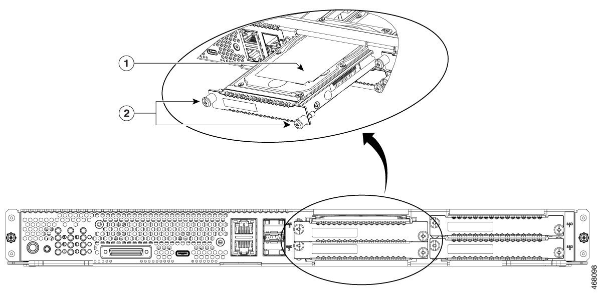
Procedure
|
Step 1 |
Shut down the UCS E-Series server x86 processor. |
||||||||
|
Step 2 |
Using either a number-1 Phillips screwdriver or a small flat-blade screwdriver, unscrew the captive screws on the faceplate and remove the cover faceplate. See the following figures. 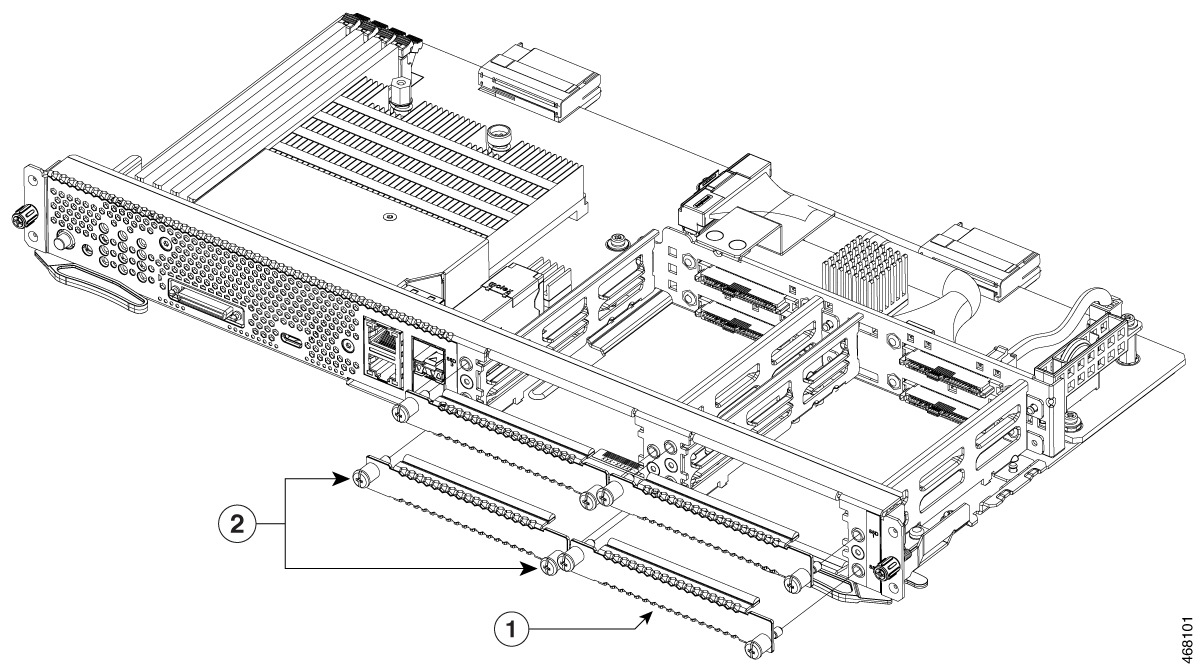
|
||||||||
|
Step 3 |
(Optional) If there is a solid-state drive, use the screwdriver to loosen the captive screws on the SSD assembly. |
||||||||
|
Step 4 |
(Optional) To remove the faulty solid-state drive, pull the handle of the SSD assembly and slide out the solid-state drive. |
||||||||
|
Step 5 |
Slide the new solid-state drive into the UCS E-Series M6 server until it clicks into place. |
||||||||
|
Step 6 |
Tighten the captive screws on the new SSD assembly. Make sure that the SSDs are firmly secured to the carrier to avoid rattling during operation. |
||||||||
|
Step 7 |
Restart the UCS E-Series M6 Server. |
Installing and Replacing the Memory DIMMS in the UCS E-Series M6 Server
Caution |
Always wear an ESD-preventive wrist strap and ensure that it makes good contact with your skin when you remove or install DIMMs. Connect the equipment end of the wrist strap to the metal part of the chassis. |
Caution |
Handle the DIMMs by the edges only. DIMMs are ESD-sensitive components and can be damaged by mishandling. |
Warning |
Statement 9001—Product Disposal Ultimate disposal of this product should be handled according to all national laws and regulations. |
Warning |
Statement 1029—Blank Faceplates and Cover Panels Blank faceplates and cover panels serve three important functions: they reduce the risk of electric shock and fire, they contain electromagnetic interference (EMI) that might disrupt other equipment, and they direct the flow of cooling air through the chassis. Do not operate the system unless all cards, faceplates, front covers, and rear covers are in place. |
This section includes the following topics:
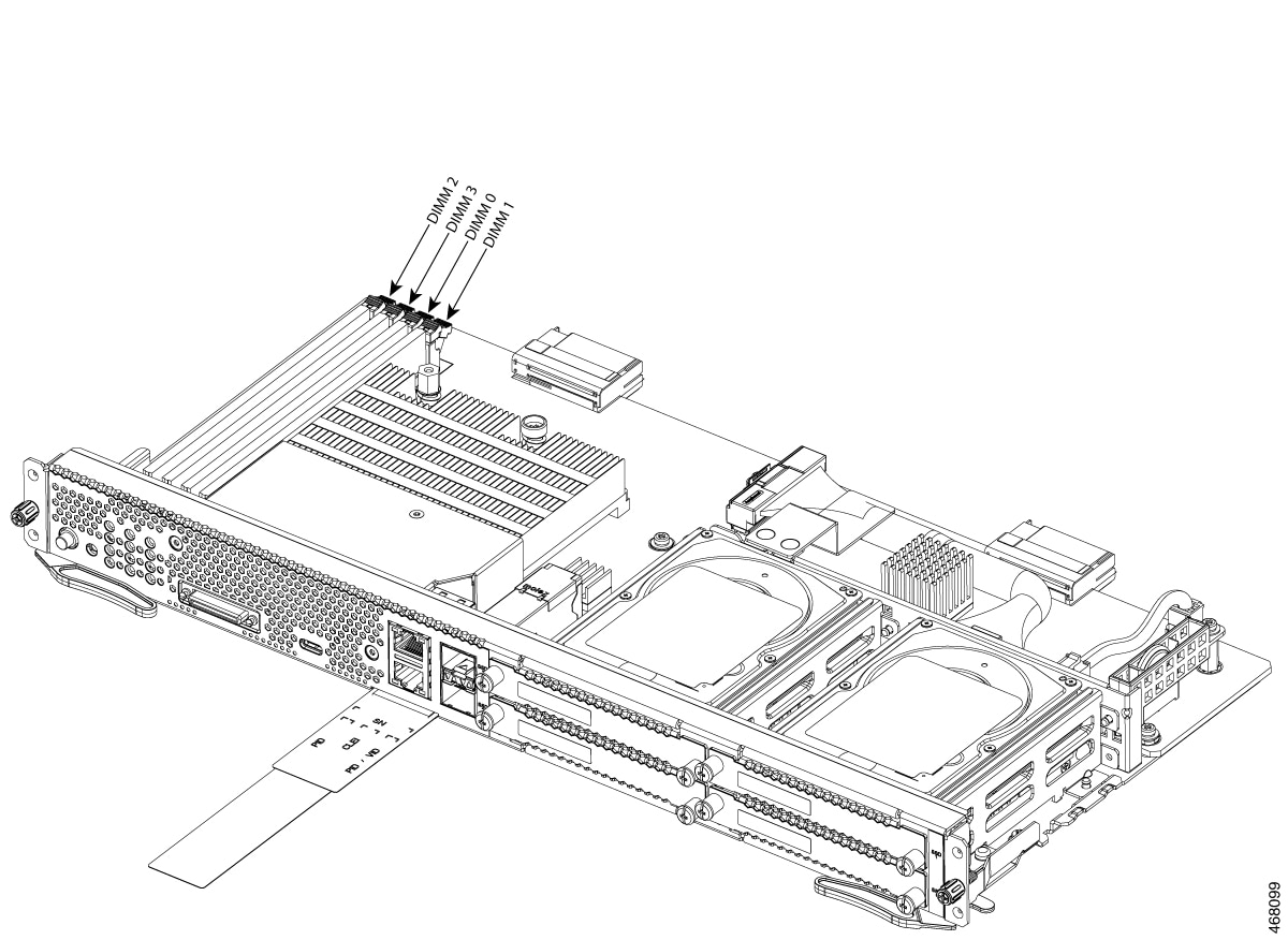
Memory DIMM Location
Note |
The UCS E-Series M6 Servers support up to 128 GB of DDR4 memory DIMMs. |
The following figure shows the location of the memory DIMMs in the UCS E-Series M6 Server. The DIMM slot number is marked on the PCB approximately in the location the arrows are pointing in the figure below:
Removing the Memory DIMM
Before You Begin
Make sure that you connect the wrist-strap clip to an unpainted portion of the chassis frame to channel unwanted ESD voltages to ground.
Procedure
Procedure
|
Step 1 |
Turn off power to the router. |
||
|
Step 2 |
Locate the DIMM on the UCS E-Series M6 Server. See the section Memory DIMM Location. |
||
|
Step 3 |
Pull the latches away from the DIMM at both ends to lift the DIMM slightly.
|
||
|
Step 4 |
Pull the DIMM out of the socket as shown in the following figure. 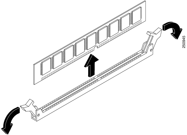
|
||
|
Step 5 |
Place the DIMM in an antistatic bag to protect it from ESD damage. |
Installing the Memory DIMM
For information about the memory on the router, see the appropriate router documentation. For information about the memory on the UCS E-Series M6 Server, see the requirements of the installed operating system.
The UCS E-Series M6 Servers support up to 128 GB of DDR4 memory DIMMs.
Performance degradation can occur if you use the following memory configuration:
-
Mix DIMM sizes and densities within a channel.
-
Partially populate a channel.
DIMMs must be installed in the following order in the UCS E-Series M6 Servers:
-
DIMM 0/2
-
DIMM 2/0
-
DIMM 1/3
-
DIMM 3/1
Note |
DIMM 0 must be plugged before DIMM 1, and DIMM 2 must be plugged before DIMM 3. |
Before You Begin
Make sure that you connect the wrist-strap clip to an unpainted portion of the chassis frame to channel unwanted ESD voltages to ground.
Procedure
Procedure
|
Step 1 |
Turn off power to the router. |
||
|
Step 2 |
Remove the UCS E-Series M6 server. |
||
|
Step 3 |
Locate the DIMM connector. See the section Memory DIMM Location . |
||
|
Step 4 |
Make sure that both latches on the DIMM connector are in the open position. |
||
|
Step 5 |
Orient the DIMM so that the polarization notch on the DIMM lines up with the notch on the connector. 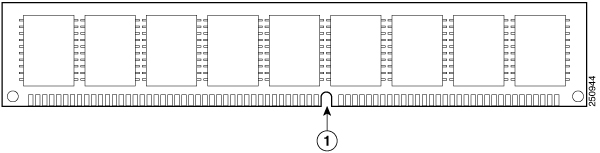
|
||
|
Step 6 |
Insert the DIMM into the connector. |
||
|
Step 7 |
Carefully and firmly press the DIMM into the connector until the latches close onto the DIMM. Make sure that both latches snap to the closed position against the DIMM. 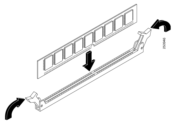
|
||
|
Step 8 |
Replace the UCS E-Series M6 Server. |
Cisco Integrated Management Controller
Cisco Integrated Management Controller (CIMC) is a separate management module built into the motherboard. CIMC is the management service for the Cisco UCS E-Series M6 Servers. You can use a web-based GUI or SSH-based CLI to access, configure, administer, and monitor the server. For more information on CIMC, see the GUI Configuration Guide for Cisco UCS E-Series M6 Server.
Related Documentation
For more information about Cisco UCS E-Series M6 Servers, see the following related documentation:
-
Regulatory Compliance and Safety Information for Cisco UCS E-Series M6 Server
-
XML API Guide for Cisco UCS E-Series M6 Server
 Feedback