Supporting and Using Additional CLI Access Options
Available Languages
Table Of Contents
Supporting and Using Additional CLI Access Options
Setting Up CP Port Connections
Setting Up Terminal Server Connections
Setting Up Local LAN Connections
Setting Up Dial-Up Connections
Starting a CLI Management Session Using a CP Port or Terminal Server Connection
Starting a Secure (SSH) CLI Session
Ending a CLI Management Session
Supporting and Using Additional CLI Access Options
The command line interface (CLI) management tool allows you to configure the MGX switches and display the switch status. When a switch starts up for the first time, the only CLI access available is through the console port (CP). After the switch is properly configured, you can access the CLI using any of the following:
•
CP connection
•
•
•
•
The following sections describe how to prepare the switch for the different types of CLI access and how to access the switch using these access methods.
Setting Up CP Port Connections
The Console Port (CP) connection requires no configuration on the switch. Figure C-1 shows the hardware required for a console port connection to a PXM-UI-S3 back card.
Figure C-1 Workstation Connection to the Console Port
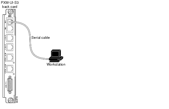
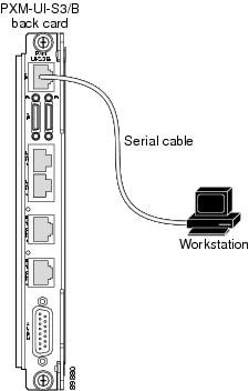
Figure C-2 shows the hardware required for a console port connection to a PXM-UI-S3/B back card.
Figure C-2 Workstation Connection to Console Port on a PXM-UI-S3/B Back Card
The terminal you use should emulate a VT-100 terminal. You can use any personal computer or UNIX workstation and a terminal emulation program that emulates the VT-100.
The default switch configuration supports the following settings: 9600 bps, 8 data bits, no parity, 1 stop bit, no hardware flow control.
Setting Up Terminal Server Connections
A terminal server connection allows remote access to the CP port. Figure C-3 shows the hardware required for a terminal server connection.
Figure C-3 Terminal Server Connection to the Console Port on a PXM-UI-S3 Back Card
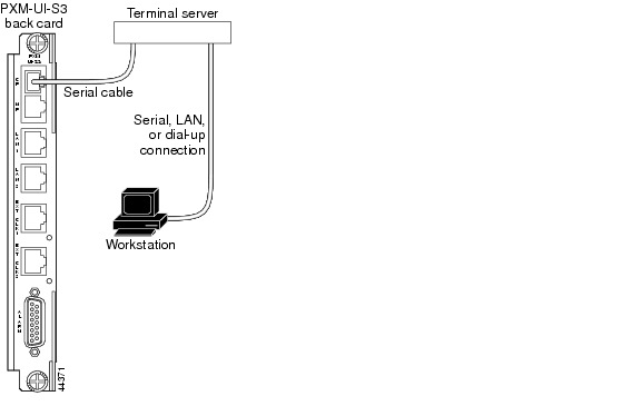
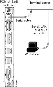
Figure C-4 shows the hardware required for a terminal server connection.
Figure C-4 Terminal Server Connection to the Console Port on a PXM-UI-S3/B Back Card
In the terminal server topology, any workstation with access to the terminal server can access the CP port as if the workstation were local. When the switch is operating properly, a terminal server connection offers no advantage over the other access methods. When the switch is not operating properly, however, other access methods might not function. In these situations, the CP port is more likely to operate than the other methods because it does not require IP connectivity to the workstation.
No special switch configuration is required to support a terminal switch configuration. The connection between the terminal server and the switch is a serial connection, which is the same as for a CP port connection. The following configuration tasks need to be completed at the terminal server:
•
•
The workstation interface can be any interface type that both the workstation and the terminal server support. For example, the workstation interface could be an Ethernet interface for local LAN access, or it could be a dial-in interface for remote access.
To access the switch through the terminal server, the workstation establishes a connection to the terminal server using a terminal emulation program. After connecting to the terminal server, the workstation user enters a command that selects the serial port to the switch. Once the correct port is selected, the user logs in to the switch as if the user were using a CP port connection.
Setting Up Local LAN Connections
The procedure for setting up local LAN connections is described in Chapter 2, "Configuring General Switch Features" in the following sections:
•
•
Setting Up Dial-Up Connections
A dial-up connection extends switch management to all workstations that have access to the Public Switched Telephone Network. Figure C-5 shows the hardware required for a dial-up connection to a PXM-UI-S3 back card.
Figure C-5 Hardware Required for Dial-up Connection to a PXM45 UI-S3 Back Cards
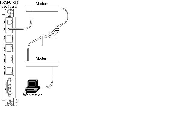
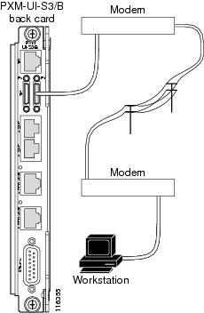
Figure C-6 shows the hardware required for a dial-up connection to a PXM1E UI-S3/B back card.
Figure C-6 Hardware Required for Dial-up Connections on a PXM-UI-S3/B Back Card
Before you can manage the switch using the dial-up interface, you must first assign an IP address to the maintenance port on the switch. This maintenance port is located on the PXM back card. For more information on physically connecting a modem to the maintenance port, refer to the Cisco MGX 8800/8900 Series Hardware Installation Guide, Releases 2 - 5.1.
To configure an IP address on the switch maintenance port, use the following procedure.
Step 1
Step 2
mgx8850a.7.PXM.a> dspipif sl0
Note
In the IP Interface Configuration Table, look for an Internet address entry under the sl0 entry. (You may need to press Enter to see this.) If an IP address is configured, you can use that address and skip the rest of this procedure. However, if the address has not been entered or is incompatible with your network, you must configure a valid IP address as described in the next step.
Step 3
mgx8850a.7.PXM.a> ipifconfig sl0 <IP_Addr> <netmask Mask>Replace <IP_Addr> with the IP address you want this port to use, and replace <Mask> with the network mask used on this network.

Tip
Note
After you complete this procedure, the switch is ready for configuration through the maintenance port.
Configuring the Switch
To support IP connectivity over the ATM interface, you need to do the following tasks:
1.
2.
3.
4.
To configure the switch to support IP connectivity to the ATM interface, use the following procedure.
Step 1
Step 2
mgx8850a.7.PXM.a> dspipif atm0
Note
In the IP Interface Configuration Table, look for an Internet address entry under the atm entry. If an IP address is configured, you can use that address. However, if the address has not been entered or is incompatible with your network, you must configure a valid IP address as described in the next step.
Step 3
mgx8850a.7.PXM.a> ipifconfig atm0 <IP_Addr> <netmask Mask>Replace <IP_Addr> with the IP address you want this port to use, and replace <Mask> with the network mask used on this network.
Note
Tip
Note
Step 4
mgx8850a.7.PXM.a> dspipif atm0Step 5
Step 6
mgx8850a.7.PXM.a> svcifconfig atm0 local <ATM_Addr>Replace ATM_Addr with the AESA for the interface. This address must conform to the address plan for the switch.
Step 7
mgx8850a.7.PXM.a> svcifconfig atm0 router <ATM_Addr>Replace <ATM_Addr> with the AESA for the interface. This address must conform to the address plan for the switch.
Step 8
mgx8850a.7.PXM.a> dspsvcifStep 9
Step 10
The line configuration should specify a UNI port, SCT 6, and a partition that supports at least 20 connections.
Step 11
The ATM addresses of directly attached ATM routers should appear in the list the switch displays. To display an ATM address for a remote router, you need to establish a CLI session on the remote switch and enter the dsppnsysaddr command.
Step 12
The following example shows commands that you can use to configure a Cisco Cisco MGX 8850 (PXM1E/PXM45) or Cisco MGX 8830 for IP communications over ATM.
Example C-1 Switch Commands for IP Communications over ATM
mgx8850a.7.PXM.a> ipifconfig atm0 A.B.E.F # Replace A.B.E.F with IP Addressmgx8850a.7.PXM.a> svcifconfig atm0 local 47.0091.8100.0000.0010.7b65.f258.0010.7b65.1111.01mgx8850a.7.PXM.a> svcifconfig atm0 router 47.0091.8100.0000.0010.7b65.f258.0010.7b65.ffff.f1mgx8850a.7.PXM.a> addcontroller 2 i 2 7 #if controller does not already existmgx8850a.7.PXM.a> cnfcdsct 6mgx8850a.7.PXM.a> upln 1.1mgx8850a.7.PXM.a> addport 1 1.1 96000 96000 6 1mgx8850a.7.PXM.a> addpart 1 1 2 500000 500000 500000 500000 1 20 32 52 1 20mgx8850a.7.PXM.a> upport 1mgx8850a.7.PXM.a> cnfilmi -if 1 -id 1 -ilmi 1 -vpi 0 -vci 16 -trap 1 -s 10 -t 10 -k 10 #Optional. This command configures ILMI for the port.mgx8850a.7.PXM.a> addaddr 10:1.1:1 47.0091.8100.0000.0010.7b65.f258.0010.7b65. ffff.f1 160 #Enter only at switch with direct connection to router. Omit if using ILMI.mgx8850a.7.PXM.a> dsppnsysaddr(example output)47.0091.8100.0000.0010.7b65.f258.0010.7b65.ffff/152Type: uni Port id: 17111041mgx8850a.7.PXM.a> dsppnports(example output)Per-port status summaryPortId IF status Admin status ILMI state Total Activeconns10:1.1:1 up up Undefined 3Configuring the Router
To support IP over ATM communications on the ATM router, you need to configure the following interfaces:
•
•
To configure the ATM interface to the switch, you need to do the following tasks:
•
•
•
•
If the router IP address for the ATM interface is on the same subnet as the IP address on the switch ATM interface, no additional configuration is required for the router IP LAN interface.
To configure the IP interface to the LAN, you need to do the following:
•
•
The procedure you use to configure the ATM router will depend on the router you are using. The following example lists commands you can use on a Cisco router to support IP over ATM communications with the Cisco MGX switch.
Example C-2 Router Configuration Commands for IP Communications over ATM
config termip routingip route 0.0.0.0 0.0.0.0 W.X.Y.Z 1 (set default route)interface atm 0ip address A.B.C.D G.H.I.J # G.H.I.J = netmaskatm nsap-address 47.0091.8100.0000.0010.7b65.f258.0010.7b65.ffff.f1atm uni-version 3.1atm pvc 1 0 5 qsaalatm pvc 2 0 16 ilmi #Optional. Enter to enable ILMI.atm ilmi-keepalive 10 #Optional. Enter to configure ILMI.atm esi-address 00107B65FFFF.F1 #Optional. Enter to support ILMI.atm arp-server selfno shut^Zwrite memoryStarting a CLI Management Session Using a CP Port or Terminal Server Connection
The process for starting a CLI management session is similar for both CP port and terminal server connections. Both use a serial connection to the switch. The difference is that terminal server connections require that you first select the correct port at the terminal server.
After switch initialization, you can terminate and start sessions at any time using the terminal or workstation connection to the CP port or terminal server.
To start a CLI management session for CP port and terminal server connections, use the following procedure.
Step 1
For instructions on preparing the terminal and the connection, refer to the procedure in the previous section.
Step 2
The following example shows the commands that accomplish this on a Cisco 2509-RJ Router.
User Access VerificationPassword:router>telnet 10.1.1.1 2001Trying 10.1.1.1, 2001 ... OpenLogin:In the example above, the user first logs into the terminal server and then establishes a Telnet session to the terminal server using port 2001. All workstation communications pass through the Telnet server on the terminal server and out the serial connection designated by port 2001.
Note
Step 3
Step 4
Login: superuserpassword:pop20one.7.PXM.a >The switch does not display the password during login. When login is complete, the switch prompt appears, you have established a CLI management session, and you are ready to begin switch configuration and monitoring.
Starting a CLI Telnet Session
Start a CLI Telnet session when you start a CLI management session using any of the following access methods, all of which require an IP address:
•
•
•
The switch includes a Telnet server process that you can use to connect to and manage the switch. Before you can establish a CLI Telnet session, you must set up the hardware for your access method and configure the switch as described earlier in the appendix.
After the appropriate interface has been configured and a physical path established to the MGX switch, you can start a CLI session using a workstation with a Telnet client program and the switch IP address. To establish a CLI management session, use the following procedure.
Step 1
You will need the telephone number for the line connected to the modem at the switch. For instructions on establishing the connection to the switch, refer to the documentation for the workstation and modem.
Step 2
C:>telnet <ipaddress>Replace <ipaddress> with the IP address assigned to the switch. If the switch is configured to support multiple access methods, be sure to use the correct IP address for the access method you are using. For example, if you are using the local LAN access method, use the IP address configured for the lnPCI0 interface.
Note
Step 3
The Login prompt comes from the switch and indicates that the workstation has successfully connected to the switch.
Step 4
Step 5
After you successfully log in, a prompt appears that is similar to the following example:
mgx8850a.7.PXM.a >The switch does not display the password during login. When the login is complete, the switch prompt appears, you have established a CLI management session, and you are ready to begin switch configuration and monitoring.
Starting a Secure (SSH) CLI Session
A secure CLI session uses the SSH protocol to encrypt all communications between a management workstation and the switch. This keeps the user ID, the password, and the details of your management session private.
Beginning with Release 5, Cisco MGX switches include an SSH server which is enabled by default. To establish a secure CLI session, you need to acquire SSH client software (which is not provided) and configure it for access to the server. The SSH secure session feature supports the following:
•
•
•
•
•
•
•
•
Tip
You can establish a secure CLI management session using any of the following access methods, all of which require an IP address:
•
•
•
Before you can establish a secure CLI management session, you must set up the hardware for your access method and configure the switch as described earlier in the appendix. After the appropriate interface has been configured and a physical path established to the MGX switch, you can start a secure CLI session using a workstation with a SSH client program and the switch IP address. To establish a CLI management session, use the following procedure.
Note
Step 1
You will need the telephone number for the line connected to the modem at the switch. For instructions on establishing the connection to the switch, refer to the documentation for the workstation and modem.
Step 2
Note
When you have successfully established a secure CLI session, the SSH client will display information similar to the following:
SSH Secure Shell 3.2.0 (Build 267)Copyright (c) 2000-2002 SSH Communications Security Corp - http://www.ssh.com/This copy of SSH Secure Shell is a commercial versionlicensed to Cisco IT, Cisco Systems.PXM1E_SJ.7.PXM.a >Step 3
The switch prompt comes from the switch and indicates that the workstation has successfully connected to the switch. When the SSH Secure Shell message appears with the switch prompt, you have established a secure CLI management session, and you are ready to begin switch configuration and monitoring.
Ending a CLI Management Session
CLI management sessions automatically terminate after the configured idle time. The default idle time is 600 seconds (10 minutes) and can be changed with the timeout command. To end a CLI management session, enter the bye command.
Note
If you have not terminated a nonTCP connection after entering the bye command, you can restart a CLI management session by pressing Return. After you press Return, the switch prompts you for a username and password. The bye command terminates a TCP connection, so you must reestablish a TCP connection before you can restart a CLI management session.
 Feedback