- About This Manual
- Overview of the Cisco MGX RPM
- Preparing to Install the Cisco MGX RPM
- Installing the Cisco MGX RPM
- Cabling Cisco MGX RPM Port Adapters
- Configuring the Cisco MGX RPM
- Setting Up Connections Between Other Devices and the RPM
- Configuring MPLS and VPN
- Maintaining the Cisco MGX RPM
- Cable and Connector Specifications
- Glossary
RPM-PR Installation and Configuration
Bias-Free Language
The documentation set for this product strives to use bias-free language. For the purposes of this documentation set, bias-free is defined as language that does not imply discrimination based on age, disability, gender, racial identity, ethnic identity, sexual orientation, socioeconomic status, and intersectionality. Exceptions may be present in the documentation due to language that is hardcoded in the user interfaces of the product software, language used based on RFP documentation, or language that is used by a referenced third-party product. Learn more about how Cisco is using Inclusive Language.
- Updated:
- March 21, 2015
Chapter: Overview of the Cisco MGX RPM
Overview of the MGX RPM
This chapter provides an overview of the MGX Route Processor Module (RPM) and its relationship to the MGX 8230, MGX 8250, and MGX 8850 switch.
This chapter contains the following sections:
•![]() ATM Deluxe Integrated Port Adapter
ATM Deluxe Integrated Port Adapter
•![]() Cisco IOS Software Compatibility
Cisco IOS Software Compatibility

Note ![]() Unless otherwise noted, RPM refers to both the RPM/B and RPM-PR. Also, unless otherwise noted, MGX 8850 refers to the MGX 8230, MGX 8250, and the MGX 8850 Release 1 switches and chassis.
Unless otherwise noted, RPM refers to both the RPM/B and RPM-PR. Also, unless otherwise noted, MGX 8850 refers to the MGX 8230, MGX 8250, and the MGX 8850 Release 1 switches and chassis.
Performance
The RPM is a high performance router module based on the Cisco 7200 router and modified to fit into a full-height MGX 8850, MGX 8250 and MGX 8230 service module slot (see Figure 1-1). The RPM is available in the following versions:
•![]() The RPM/B is based on the Cisco 7200 NPE-150 router engine that is capable of processing up to 140 kpps (kilo-packets per second).
The RPM/B is based on the Cisco 7200 NPE-150 router engine that is capable of processing up to 140 kpps (kilo-packets per second).
•![]() The RPM-PR is a high-performance router module based on an NPE-400 processor, featuring an upgraded QED RM7000 processor subsystem that provides performance of more than 300 kpps throughput for IP packet forwarding.
The RPM-PR is a high-performance router module based on an NPE-400 processor, featuring an upgraded QED RM7000 processor subsystem that provides performance of more than 300 kpps throughput for IP packet forwarding.
The RPM provides integrated IP in an ATM platform, enabling services such as integrated Point-to-Point Protocol (PPP), Frame Relay termination, and IP virtual private networks (VPNs) using MPLS technology. It provides Cisco IOS(tm)-based multiprotocol routing over ATM, Frame Relay and ATM Interface Layer 3 Termination, Local Server Interconnect over High-Speed LANs, Access Concentration, and switching between Ethernet LANs and the WAN facilities of the MGX 8850.
The RPM includes interprocessor communication to the main processor switch control module for management, including configuration, mode supervision, (for example, redundancy/load sharing control) and software and configuration file management.
Physical Overview
The RPM module fits in a 32-slot, full-height MGX 8850 chassis and connects to the PXM and other service modules via the midplane.
The RPM receives power from the midplane and communicates over the midplane with the PXM using IPC over ATM. The RPM runs Cisco IOS software.
The RPM installs into one slot in the MGX 8850 chassis and connects to the MGX 8850 midplane (see Figure 1-1). When the RPM is installed (in the front of the MGX 8850 chassis), its back cards must also be connected to the midplane (from the rear of the MGX 8230, MGX 8250 or MGX 8850 chassis) and their ports must be cabled to network devices. (See Figure 1-2.) See "Cabling the MGX RPM Back Cards" for cable and connection details.
The RPM has an integrated ATM interface—a permanently attached ATM port adaptor based on the Cisco ATM Deluxe module—and can support up to two optional back cards to provide LAN connectivity (see Figure 1-3). The two back cards can be either a four-port Ethernet or a one-port Fast Ethernet.
All RPM trunk traffic travels over its integrated ATM interface to the MGX 8850 cellbus (the ATM port is connected to the cellbus), or to the PXM uplink to the PXM, which routes it to the appropriate service module or RPM Both the RPM and the PXM are configured manually to create the appropriate connections before any user data can flow through the PXM.
Note ![]() Slots 7 and 8 are reserved for the PXM cards occupying the full height of the chassis (see Figure 1-1, which shows the PXM cards installed in the front of the MGX 8850 chassis).
Slots 7 and 8 are reserved for the PXM cards occupying the full height of the chassis (see Figure 1-1, which shows the PXM cards installed in the front of the MGX 8850 chassis).
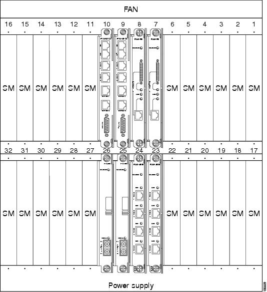
In Figure 1-2, which shows the rear view of the MGX 8850 chassis, PXM-UI cards are visible in the top slots and T3 cards in the bottom slots, directly behind the PXMs. In the same illustration, RPM cards are installed in slots 9 and 10 and occupy the full height of the chassis. FE and 4E cards are installed in the bottom slots, directly behind the RPM cards.
Note ![]() FDDI cards must be installed in the top slot of the RPM/B. (RPM-PR does not support FDDI cards.)
FDDI cards must be installed in the top slot of the RPM/B. (RPM-PR does not support FDDI cards.)
Figure 1-1 RPM Installed in a MGX 8250 or MGX 8850 Chassis (Front View)
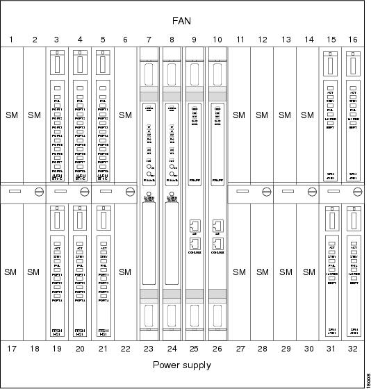
Figure 1-2 RPM Back Cards and Service Modules Installed in an MGX 8250 or MGX 8850 (Back View)
The RPM/B and RPM-PR use NPE-150 and NPE-400 router engines, respectively. They also use an integrated ATM interface and a cellbus ASIC to interface with the MGX 8850 cellbus controllers.
The MGX 8850 shelf can be completely populated with 12 RPM blades, which allows you to use multiple RPMs to achieve load sharing. Load sharing is achieved by manually distributing connections across multiple embedded RPM router blades.
Figure 1-3 RPM Connected to the MGX 8230, MGX 8250 or MGX 8850 Midplane and Back Cards
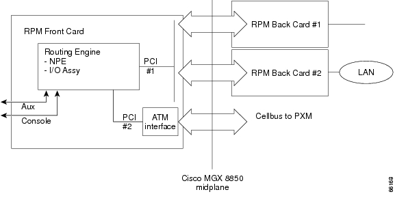
The RPM fits into the MGX 8850 midplane architecture so that the front card provides Cisco IOS router services, and the back cards provide physical network connectivity. The RPM front card also provides ATM connectivity to MGX 8230, MGX 8250 or MGX 8850 cellbuses at full-duplex OC-6.
The RPM back cards are connected to the front card by a dual PCI bus (refer to Figure 1-3). Each RPM card can be equipped with two single-height back cards. Initially, two single-height back card types are supported. They are
•![]() 4-port Ethernet
4-port Ethernet
•![]() 1-port Fast Ethernet
1-port Fast Ethernet
Although in most service provider network cores, the recommended routing protocols are OSPF or IS-IS, with additional use of BGP, where appropriate, the RPM supports all of the following IP routing protocols:
•![]() static route
static route
•![]() IGRP
IGRP
•![]() RIPv1
RIPv1
•![]() RIPv2
RIPv2
•![]() OSPF
OSPF
•![]() EIGRP
EIGRP
•![]() IS-IS
IS-IS
•![]() BGP with multiprotocol extensions
BGP with multiprotocol extensions
Note ![]() MAC addresses remain with the chassis slot, not with a particular card or interface. Any new RPM card placed in a slot will receive the MAC address previously assigned to that slot. Moving an RPM card to a different slot or chassis results in its receiving a new MAC address.
MAC addresses remain with the chassis slot, not with a particular card or interface. Any new RPM card placed in a slot will receive the MAC address previously assigned to that slot. Moving an RPM card to a different slot or chassis results in its receiving a new MAC address.
System Specifications
Table 1-1 summarizes the key attributes of the RPM cards.
MGX 8850 Cellbus
The MGX 8850 cellbus in the MGX 8850 midplane communicates between the RPM, service modules (cellbus slaves), and the PXM (cellbus master) (see Figure 1-3). Each cellbus is connected to a set of PXM cards. Only one cellbus may be active at a time.
Communication from master to slaves consists of a broadcast to all slaves. The first byte of the cell header contains addressing information. Each slave will monitor data traffic and "pick up" cells that are destined to its slot. Also, a multicast bit allows all slaves to receive a cell simultaneously.
Communication from the slaves to the master is complicated, because many slaves may attempt to transmit simultaneously, requiring arbitration among slaves. At the start of a given cell period, the master will poll all slaves to see if they have anything to send. By the end of the current cell, the master will grant or allow one of the slaves to transmit. Polling and data transmission occur simultaneously.
ATM Deluxe Integrated Port Adapter
The ATM deluxe port adapter provides a single ATM interface to the MGX 8850 cellbus interface (CBI). The ATM port adapter is a permanent, internal ATM interface. As such, it has no cabling to install and does not support interface types. It connects internally, directly to the MGX 8850 midplane.
The CBI is derived from several modules. There are two distinct blocks, one is the ATM SAR function and the other is the cellbus controller ASIC. The ATM SAR function is based on the ATM Deluxe Dual SAR design and is implemented with two LSI ATMizerIIs. For the RPM, the design is implemented with two ATMizerII+. The cellbus controller is based on the Cisco WAN cellbus ASIC.
The following features from the ATM Deluxe port adapter are supported on the MGX 8850 switch:
•![]() ATM layer
ATM layer
–![]() Support for all 24 bits of the UNI VP/VC field, any arbitrary address
Support for all 24 bits of the UNI VP/VC field, any arbitrary address
–![]() Respond to OAM flows (F4/F5)
Respond to OAM flows (F4/F5)
–![]() AAL5 for data traffic
AAL5 for data traffic
•![]() Traffic management
Traffic management
–![]() Full ABR and VBR-nrt support (TM 4.0), all modes
Full ABR and VBR-nrt support (TM 4.0), all modes
–![]() Per VC rates from 2.3 kbps to 155 Mbps, in 2.3 kbps increments
Per VC rates from 2.3 kbps to 155 Mbps, in 2.3 kbps increments
RPM Midplane Connector
The MGX 8850 cellbus and the RPM back cards connect through two sets of connectors placed at the rear of the RPM motherboard (see Figure 1-3). Each connector has 360 pins, for a total of 720 pins.
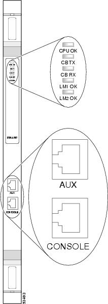
Front Panel LEDs
The LEDs indicate the current operating condition of the RPM (see Figure 1-4). You can observe the LEDs and note the fault condition the RPM is encountering. If you need assistance, contact your system administrator or TAC, if necessary. For a table showing how to interpret RPM front panel LED activity, see "Maintaining the MGX RPM," the "Reading Front Panel LEDs" section.
Figure 1-4 Front Panel of the RPM-PR
Cisco IOS Software Compatibility
This RPM release is supported in Cisco IOS Release 12.2(4)T.
For more information about RPM software configuration, refer to the Cisco IOS Configuration and Command Reference publications.
 Feedback