Release Notes for the Catalyst 3750 Metro Switch, Cisco IOS Release 12.2(54)SE
Available Languages
Table Of Contents
Release Notes for the Catalyst 3750 Metro Switch
Cisco IOS Release 12.2(54)SEFinding the Software Version and Feature Set
Upgrading a Switch by Using the CLI
Recovering from a Software Failure
Minimum Cisco IOS Release for Major Features
Bidirectional Forwarding Detection
Connectivity Fault Management (CFM)
Hot Standby Routing Protocol (HSRP)
IP Service Level Agreements (SLAs)
logging event-spanning-tree Command
Multiprotocol Label Switching (MPLS) and Ethernet over MPLS (EoMPLS)
Resilient Ethernet Protocol (REP)
Updates to the Software Configuration Guide for Cisco IOS Release 12.2(54)SE
"Configuring IP Unicast Routing" Chapter
"Configuring IEEE 802.1Q and Layer 2 Protocol Tunneling" Chapter—New Section
"Configuring Ethernet OAM, CFM, and E-LMI" Chapter—New Section
Configuring CFM on C-VLAN (Inner VLAN)
"Unsupported Commands" Appendix
Updates to the Software Configuration Guide for Cisco IOS Release 12.2(52)SE
"Configuring IP Unicast Routing" Chapter
"Configuring Ethernet OAM, CFM, and E-LMI" Chapter
"Configuring IEEE 802.1x Port-Based Authentication" Chapter
Updates to the Command Reference for Cisco IOS Release 12.2(54)SE
Updates to the System Message Guide
Update to the Hardware Installation Guide
Obtaining Documentation, Obtaining Support, and Security Guidelines
Release Notes for the Catalyst 3750 Metro Switch
Cisco IOS Release 12.2(54)SE
April 20, 2010
Cisco IOS Release 12.2(54)SE runs on the Catalyst 3750 Metro switch.
These release notes include important information about Cisco IOS Release 12.2(54)SE and any limitations, restrictions, and caveats that apply to the releases.
Verify that these release notes are correct for your switch:
•
If you are installing a new switch, see the Cisco IOS release label on the rear panel of your switch.
•
•
For the complete list of switch documentation, see the "Related Documentation" section.
You can download the switch software from this site:
http://tools.cisco.com/support/downloads/go/MDFTree.x?butype=switches
Contents
•
•
•
Hardware Supported
Table 1 lists the supported hardware and the minimum Cisco IOS release required.
Table 1 Supported Hardware
Catalyst 3750 Metro 24-AC switch
24 10/100 Ethernet ports, 2 1000X standard SFP1 module slots, 2 1000X ES2 SFP slots, and field-replaceable AC power supply
Cisco IOS Release 12.1(14)AX
Catalyst 3750 Metro 24-DC switch
24 10/100 Ethernet ports, 2 1000X standard SFP module slots, 2 1000X ES SFP slots, and field-replaceable DC power supply
Cisco IOS Release 12.1(14)AX
SFP modules
1000BASE-T, 1000BASE-SX, and 1000BASE-LX
Cisco IOS Release 12.1(14)AX
1000BASE-ZX and CWDM3
Cisco IOS Release 12.1(14)AX1
100BASE-FX MMF4
Cisco IOS Release 12.2(25)EY
1000BASE-BX
Cisco IOS Release 12.2(25)EY2
DOM5 support for GLC-BX, CWDM, and DWDM SFPs
Cisco IOS Release 12.2(44)SE
1000BASE-LX/LH MMF and SMF
1000BASE-SX MMF
DOM support for GLC-ZX-SM SFP, 1000BASE-LX/LH, and 1000BASE-SX
1000 FX GLC-EX-SMG SFP
Cisco IOS Release 12.2(46)SE
Additional DWDM SFP qualifications
Cisco IOS Release 12.2(50)SE
For a complete list of supported SFPs and part numbers, see the Catalyst 3750 Metro data sheet at:
1 SFP = small form-factor pluggable
2 ES = enhanced services
3 CWDM = coarse wavelength-division multiplexer
4 MMF = multimode fiber
5 DOM = digital optical monitoring
Upgrading the Switch Software
•
•
•

Note
Finding the Software Version and Feature Set
The Cisco IOS image is stored as a bin file in a directory that is named with the Cisco IOS release. The image is stored on the system board flash device (flash:).
You can use the show version privileged EXEC command to see the software version that is running on your switch.
You can also use the dir filesystem: privileged EXEC command to see the directory names of other software images that you might have stored in flash memory.
Deciding Which Files to Use
The upgrade procedures in these release notes describe how to perform the upgrade by using a combined tar file. This file contains the Cisco IOS image file. To upgrade the switch through the command-line interface (CLI), use the tar file and the archive download-sw privileged EXEC command.
Table 2 lists the software filename for this software release.
Table 2 Cisco IOS Software Image Files for Catalyst 3750 Metro Switches
Filename
c3750me-i5k91-tar.122-54.SE.tar
Cisco IOS cryptographic image tar file.
This image has the Kerberos, SSH1 , SSL2 , Layer 2+, and Layer 3 features.
1 SSH = Secure Shell
2 SSL = Secure Socket Layer
Archiving Software Images
Before upgrading your switch software, make sure that you have archived copies of the current Cisco IOS release and the Cisco IOS release to which you are upgrading. You should keep these archived images until you have upgraded all devices in the network to the new Cisco IOS image and until you have verified that the new Cisco IOS image works properly in your network.
Cisco routinely removes old Cisco IOS versions from Cisco.com. See Product Bulletin 2863 for more information:
http://www.cisco.com/en/US/partner/products/sw/iosswrel/ps5187/prod_bulletin0900aecd80281c0e.
HtmlYou can copy the bin software image file on the flash memory to the appropriate TFTP directory on a host by using the copy flash: tftp: privileged EXEC command.
Note
You can also configure the switch as a TFTP server to copy files from one switch to another without using an external TFTP server by using the tftp-server global configuration command. For more information about the tftp-server command, see the "Basic File Transfer Services Commands" section of the Cisco IOS Configuration Fundamentals Command Reference, Release 12.2 at this URL:
Upgrading a Switch by Using the CLI
This procedure is for copying the tar file to the switch. You copy the file to the switch from a TFTP server and extract the files. You can download an image file and replace or keep the current image.
Download the software from Cisco.com to your management station by following these steps:
Step 1
Step 2
Go to this URL and log in to download the appropriate files:
http://www.cisco.com/kobayashi/sw-center/sw -lan.shtml
To download the files, click the link for your switch platform, and then follow the links on the page to select the correct tar image file.
Step 3
For more information, see Appendix B in the software configuration guide for this release.
Step 4
Step 5
Step 6
archive download-sw /overwrite /reload tftp:[[//location]/directory]/image-name.tarThe /overwrite option overwrites the software image in flash memory with the downloaded one.
The /reload option reloads the system after downloading the image unless the configuration has been changed and not been saved.
For //location, specify the IP address of the TFTP server.
For /directory/image-name.tar, specify the directory (optional) and the image to download. Directory and image names are case sensitive.
This example shows how to download an image from a TFTP server at 198.30.20.19 and to overwrite the image on the switch:
Switch# archive download-sw /overwrite tftp://198.30.20.19/image-name.tarYou can also download the image file from the TFTP server to the switch and keep the current image by using the /leave-old-sw option instead of the /overwrite option.
Recovering from a Software Failure
Switch software can be corrupted during an upgrade, by downloading the wrong file to the switch, and by deleting the image file. In all of these cases, the switch does not pass the power-on self-test (POST), and there is no connectivity. You can use the Xmodem protocol to recover from these failures.
For detailed recovery procedures, see the "Troubleshooting" chapter in the software configuration guide for this release.
Installation Notes
You can assign IP information to your switch by using these methods:
•
•
•
•
New Features
New Hardware Features
For a list of all supported hardware, see the "Hardware Supported" section.
New Software Features
•
•
•
•
•
Minimum Cisco IOS Release for Major Features
Table 3 lists the minimum software release required to support features on the Catalyst 3750 Metro switch.
Note
http://www.cisco.com/en/US/products/hw/switches/ps5532/products_configuration_guide_chapter09186a00801ee872.html
Limitations and Restrictions
You should review this section before you begin working with the switch. These are known limitations that will not be fixed, and there is not always a workaround. Some features might not work as documented, and some features could be affected by recent changes to the switch hardware or software.
•
•
•
•
•
•
•
•
•
Bidirectional Forwarding Detection
•
The workaround is to not use a permit ACL entry with the log option on interfaces participating in BFD. (CSCtf31731)
Configuration
•
This problem occurs under these conditions:
–
–
–
The workaround is to reconfigure the static IP address. (CSCea71176)
•
The workaround is to upgrade to Cisco IOS Release 12.2(25)EY or later. (CSCec35100)
•
These are the workarounds:
1.
2.
3.
•
–
–
–
No workaround is necessary; these are the designed behaviors. (CSCed50819)
•
However, when dynamic ARP inspection is not enabled and jumbo MTU is configured, ARP and RARP packets are correctly bridged in hardware. (CSCed79734)
•
The workaround is to configure the port for 10 Mbps and half duplex or to connect a hub or a nonaffected device to the switch. (CSCed39091)
•
When you enter the show ip arp inspection log privileged EXEC command, the log entries from all switches in the stack are moved to the switch on which the command was entered.
There is no workaround. (CSCed95822)
•
The workaround is to enter the no switchport block unicast interface configuration command for that specific interface. (CSCee93822)
•
The workaround is to statically configure the MAC address of port 1/0/3 in the CAM table of the switch bound to port 1/0/2 by using the mac address-table static mac-addr vlan vlan-id interface fastethernet1/0/2 global configuration command. (CSCee87864)
•
There is no workaround. This is a cosmetic error and does not affect the functionality of the switch. (CSCef59331)
•
2d20h: %PLATFORM_UCAST-3-LB: PI<->PD handles out of sync for Adj 222.1.1.1 LB -Traceback= 252620 A919CC A847E0 A85BE0 A927FC AA2D28 A965E0 A89C08 A78744 B08F48 ADF504 ADDC4C AE3460 AD25CC B94AA0 B94F20
There is no workaround. (CSCeh13477)
•
The workaround is to always enter a non zero value for the timeout value when you enter the boot host retry timeout timeout-value command. (CSCsk65142)
Connectivity Fault Management (CFM)
•
There is no workaround. (CSCte39713)
•
This is expected behavior. The workaround is to use the ethernet cfm mep crosscheck start-delay command to set the delay-start timer value larger than the continuity-check interval. (CSCtf30542)`
EtherChannel
•
15:50:11: %COMMON_FIB-4-FIBNULLHWIDB: Missing hwidb for fibhwidb Port-channel1 (ifindex 1632) -Traceback= A585C B881B8 B891CC 2F4F70 5550E8 564EAC 851338 84AF0C 4CEB50 859DF4 A7BF28 A98260 882658 879A58There is no workaround.(CSCsh12472)
Fallback Bridging
•
The workaround is to remove the VLAN from the bridge group or to remove the static MAC address from the VLAN. (CSCdw81955)
•
The workaround is to disable fallback bridging. To remove an interface from a bridge group and to remove the bridge group, use the no bridge-group bridge-group interface configuration command. Another workaround is to disable port security on all ports in all VLANs participating in fallback bridging by using the no switchport port-security interface configuration command. (CSCdz80499)
Hot Standby Routing Protocol (HSRP)
•
The workaround is to ensure that the ports on the standby cluster members are not in the spanning-tree blocking state. To verify that these ports are not in the blocking state, see the "Configuring STP" chapter in the software configuration guide. (CSCec76893)
•
There is no workaround. Do not configure HSRP on MPLS interfaces. (CSCeg76540)
IP
•
The workaround is to set an ARP timeout value higher than 120 seconds. (CSCea21674)
•
The workaround is to use rate limiting on DHCP traffic to prevent a denial of service attack from occurring. (CSCeb59166)
IP Service Level Agreements (SLAs)
•
There is no workaround.
IP Telephony
•
The workaround is to power the AP by using an AC wall adaptor. (CSCin69533)
•
There is no workaround. (CSCea85312)
logging event-spanning-tree Command
When the logging event-spanning-tree interface configuration command is configured and logging to the console is enabled, a topology change might generate a large number of logging messages, causing high CPU utilization. CPU utilization can increase with the number of spanning-tree instances and the number of interfaces configured with the logging event-spanning-tree interface configuration command. This condition adversely affects how the switch operates and could cause problems such as STP convergence delay.
High CPU utilization can also occur with other conditions, such as when debug messages are logged at a high rate to the console.
Use one of these workarounds:
•
•
•
•
The workaround is to configure aggressive UDLD. (CSCsh70244).
MAC Addressing
When a MAC address is configured for filtering on the internal VLAN of a routed port, incoming packets from the MAC address to the routed port are not dropped. (CSCeb67937)
Multiprotocol Label Switching (MPLS) and Ethernet over MPLS (EoMPLS)
•
The workaround is to configure the incoming ports as an IEEE 802.1Q trunk or as an access port. (CSCeb44014)
•
The workaround is to use the show mpls ldp parameter user EXEC command to see the configured value. (CSCeb76775)
•
There is no workaround. (CSCec13655)
•
This only occurs on the enhanced services ports with Multiprotocol Label Switching (MPLS) configured. The FastEthernet and Gigabit Ethernet customer edge ports are not affected.
There is no workaround. You can specify the marking as either SNMP IP DSCP or as CPU traffic QoS, not both. (CSCsl65914)
•
There is no workaround. (CSCsq24540)
Multicasting
•
•
There is no workaround because non-RPF traffic is continuous in certain topologies. As long as the trunk port is a member on a trunk port in at least one VLAN, this problem for the non-RPF traffic occurs. (CSCdu25219)
•
The workaround is to reduce the number of multicast routes and IGMP snooping groups to less than the maximum supported value. (CSCdy09008)
•
There is no workaround. (CSCdy82818)
•
The workaround is to not apply a router ACL configured to deny access to a VLAN interface. Apply the security through other means; for example, apply VLAN maps to the VLAN instead of using a router ACL for the group. (CSCdz86110)
•
Multicast is not supported on tunnel interfaceserror message. IP PIM is not supported on tunnel interfaces.There is no workaround. (CSCeb75366)
•
–
–
There is no workaround. (CSCec20128)
•
The switchport block multicast interface configuration command is only applicable to non-IP multicast traffic.
There is no workaround. (CSCee16865)
•
–
–
The workaround is to enter clear ip mroute privileged EXEC command on the interface. (CSCef42436)
•
There is no workaround. (CSCef67261)
Quality of Service (QoS)
•
•
The workaround is to choose compatible buffer sizes and threshold levels. (CSCea76893)
•
There is no workaround. (CSCeb75230)
•
There is no workaround. (CSCeb80223)
•
There is no workaround. (CSCeb80300)
•
There is no workaround. (CSCec08205)
•
The workaround is to configure explicit matches for traffic that requires priority treatment. (CSCec38901)
•
The workaround is to detach the service policy from the port while making the modifications and then to re-attach the service policy. (CSCec75945)
•
If this becomes a problem, you can change switch behavior by using the queue-limit policy-map class configuration command at the class level to set shorter queue depths. Each shaper has an associated buffer queue with a default depth of 128 packets.
For example:
Switch(config)# policy-map cos2-policySwitch(config-pmap)# class cos2Switch(config-pmap-c)# bandwidth 50000Switch(config-pmap-c)# queue-limit 32The point at which buffer memory is exhausted depends on the number of queues, the sizes of the queued packets, and whether or not the traffic pattern being sent to the switch allows the queues to drain at all.
Upgrading your switch to Cisco IOS Release 12.2(25)EY or later greatly reduces the possibility of this situation happening, although it can still occur with some configurations and traffic patterns. (CSCed83886)
•
There is no workaround. (CSCee22591)
•
The workaround is to use the CLI to enable the trap by entering the snmp-server enable traps mpls fast-reroute [protected] global configuration command. (CSCsq07065)
Resilient Ethernet Protocol (REP)
•
There is no workaround. (CSCsk00716)
•
–
–
–
–
–
You cannot enable these functions on REP segments without edge ports.
•
The workaround is to use the rep lsl-age-out timer interface configuration command to configure the REP LSL age timer for more than 1000 milliseconds (1 second). (CSCsz40613)
Routing
•
•
There is no workaround. (CSCea52915)
•
–
–
–
The workaround is to change any one of the listed conditions. (CSCed53633)
•
There is no workaround. (CSCsj41522)
SPAN and Remote SPAN (RSPAN)
•
There is no workaround for a remote SPAN session. This is a hardware limitation. (CSCdy72835)
•
The workaround is to use the encapsulate replicate keywords in the monitor session global configuration command. This is a hardware limitation. (CSCdy81521)
•
The workaround is to configure only one RSPAN source session. (CSCea72326)
•
Decreased egress SPAN rate.In all cases, normal traffic is not affected; the degradation limits only how much of the original source stream can be monitored. If fallback bridging and multicast routing are disabled, egress-SPAN monitoring is not degraded.
There is no workaround. If possible, disable fallback bridging and multicast routing. If possible, use ingress-SPAN to observe the same traffic. (CSCeb01216)
•
There is no workaround. (CSCeb23352)
•
The workaround is to use the monitor session session_number destination {interface interface-id encapsulation replicate} global configuration command for a local SPAN session. (CSCed24036)
•
There is no workaround. (CSCsj21718)
Trunking
•
There is no workaround. (CSCdz33708)
•
There is no workaround. (CSCdz42909)
•
There is no workaround. (CSCec35100).
•
3d20h: %PLATFORM_UCAST-3-LB: PI<->PD handles out of sync for Adj 222.1.1.1 LB -Traceback= 252620 A9204C A84E60 A86260 A92E7C AA36A0 AA3520 A96C60 A8A288 A78DC4 B095C8
There is no workaround. This does not affect switch functionality. (CSCeh20081)
Tunneling
•
The workaround is to configure identical VLAN mappings on both ES ports if they will be bundled into an EtherChannel. (CSCec49520)
•
The workaround is to configure the ES port as a trunk or yo use the switchport access vlan vlan_id interface configuration command to define the access VLAN for the access port. (Ctb67562)
VLAN
•
The workaround is to reduce the number of VLANs or trunks. (CSCeb31087)
•
There is no workaround. (CSCed71422)
•
The workaround is to define another policy-map name for the second-level policy-map with the same configuration to be used for another policy-map. (CSCef47377)
Important Notes
•
By definition, the local PE H-VPLS VLAN should not be relevant for the VPLS network. Because the local PE SVI with the xconnect and the remote PE SVI with the xconnect do not need to be on the same VLAN, it does not matter if the VLAN is carried across the transport network or not. However, problems could occur if a service provider deployed the Catalyst 3750M switch using the H-VPLS VLAN as the customer VLAN when H-VPLS came up with VC type 5 because the customer VLAN tag would not be consistent across the transport. The new behavior is now consistent with the Cisco default.
•
If the switch has interfaces with automatic QoS for voice over IP (VoIP) configured and you upgrade the switch software to Cisco IOS Release 12.2(40)SE (or later), when you enter the auto qos voip cisco-phone interface configuration command on another interface, you might see this message:
AutoQoS Error: ciscophone input service policy was not properly appliedpolicy map AutoQoS-Police-CiscoPhone not configuredIf this happens, enter the no auto qos voip cisco-phone interface command on all interface with this configuration to delete it. Then enter the auto qos voip cisco-phone command on each of these interfaces to reapply the configuration.
•
–
–
In Cisco IOS Release 12.2(18)SE and later, you can only use the logging on and then the no logging console global configuration commands to disable logging to the console. (CSCec71490)
•
•
Note
•
Note
Open Caveats
•
When a class-map entry is added or modified, a delay of several seconds can occur if the switch already has many policy maps defined. For example, a 6- second delay occurs when a new class map is added to the a switch that already has 400 hierarchical QoS policies defined.
The delay occurs even if the policy maps are not attached to a switch interface. The console might also be unresponsive when this occurs.
There is no workaround.
•
When Bidirectional Forwarding Detection (BFD) is enabled on an interface of a switch that is running Cisco IOS Release12.2(50)SE or later, Release 12.2(52)SE or later, or Release 12.2(54)SE, CPU spikes can occur once or twice per hour.
There is no workaround.
•
When an EtherChannel is configured for 802.1ad and a channel member that is up is removed from the EtherChannel, the 802.1ad configuration is removed. However, if the port channel is shut down and then removed from the EtherChannel, the 802.1ad configuration is not removed.
The workaround is to enter the no shutdown interface configuration command on the port channel before removing it from the EtherChannel.
•
When you configure a port for 802.1ad UNI by entering the ethernet dot1ad uni s-port interface configuration command and enter the l2protocol peer stp lldp command on a UNI-S port, STP and LLDP protocols are not peered between both switches.
The workaround, when you want to peer STP and LLDP between customer and provider edge switches and to tunnel other Layer 2 protocols, is to use the ethernet dot1ad uni c-port interface command to configure the service provider customer-facing port as a UNI-C port and not a UNI-S port. By default on UNI-C ports, all Layer 2 protocols, including STP and LLDP are peered. For protocols to be tunneled through the 802.1ad provider network, enter the l2protocol forward command on the UNI-C port.
Resolved Caveats
•
When an enhanced-services (ES) port is configured as a trunk port and the switch is using VLAN-based EoMPLS, if the VLAN has been cleared from the trunks on the ES ports, packets destined to IP addresses 224.0.0.xxx might not be sent over the EoMPLS tunnel.
The workaround is to allow the EoMPLS VLAN on the trunk on the ES ports.
•
When the status of a Resilient Ethernet Protocol (REP) primary edge port changes, for example, because you enter the no shutdown interface configuration command, the switch sends duplicate SNMP messages for the crepPortRoleChange trap.
There is no workaround.
•
A switch drops unicast traffic under these conditions:
–
–
When multicast traffic is sent in one direction and unicast traffic is sent in another, unicast traffic is dropped at the multicast traffic source port.
The workaround is to apply a policy map so that the least significant traffic is discarded.
•
The CISCO-RTTMON-MIB is not correctly implemented.
•
On a switch running Cisco IOS release 12.2(46)SE, the output of the show interfaces privileged EXEC command shows 0 packets for port channel input and output rates.
The workaround is to reload the switch by entering the reload privileged EXEC command.
•
A switch can fail when an SNMP process attempts to configure dot1x authentication when it is already configured.
There is no workaround.
•
A switch does not receive SNMP trap and inform messages from the correct interface after you enter the snmp-server trap-source loopback0 and snmp-server source-interface informs loopback0 global configuration commands.
There is no workaround.
•
Modifying a prefix list that is configured as an inbound or outbound distribute-list causes the EIGRP peer to resynchronize.
There is no workaround
•
A switch with at least one configured trunk port might fail when you use the vlan vlan-id global configuration command to configure more than 950 VLANs.
There is no workaround.
•
When you enter the no ip ftp passive global configuration command to allow all types of FTP connections on a switch running Cisco IOS Release 12.2(52)SE, FTP sessions could disable Telnet or console connections. You can no longer use the vty.
The workaround is to restart the switch. To prevent FTP sessions from disabling Telnet or console connections, enter the ip ftp passive global configuration command.
•
On a switch configured for IP routing and running Cisco IOS Release 12.2(50)SE or later, Cisco Express Forwarding (CEF) can use a large amount of memory. The IP RIB update process uses about 2000 bytes for each prefix that CEF uses.
There is no workaround. You can reduce the memory use by reducing the number of routes that the switch processes.
•
When you use the rep block port id port-id vlan vlan-list interface configuration command on a Resilient Ethernet Protocol (REP) primary edge port to block a VLAN list on one port and then use the same command to block another VLAN list on another port, the original port number and VLAN list are not overwritten. Therefore, after you have blocked a VLAN list on one port, you cannot block another VLAN list on another port.
There is no workaround.
•
When you have configured REP segment topology change notices (STCNs) and VLAN load balancing on an interface, entering the shutdown and the no shutdown command on the interface can cause a memory leak or can cause the switch to reload.
There is no workaround.
Documentation Updates
The clustering chapter has been removed from the software configuration guide and the commands removed from the command reference. The Catalyst 3750 Metro switch does not support clustering.
This section contains these documentation updates:
•
•
•
•
•
Updates to the Software Configuration Guide for Cisco IOS Release 12.2(54)SE
•
•
Configuring IEEE 802.1ad•
Configuring CFM on C-VLAN (Inner VLAN)•
"Configuring IP Unicast Routing" Chapter
In the section on Configuring BFD, Disabling BFD Echo Mode:
•
•
"Configuring IEEE 802.1Q and Layer 2 Protocol Tunneling" Chapter—New Section
Configuring IEEE 802.1ad
The Catalyst 3750 Metro switch supportS QinQ, a Cisco-proprietary system to enable double-tagging to provide VLAN scalability in the provider network, and Layer 2 protocol tunneling for tunneling customer control packets. IEEE 802.1ad uses standard protocols to solve VLAN scalability in provider networks. As with QinQ, data traffic entering from the customer interface is tagged with a service-provider tag. The customer frame crosses the provider network with two tags: the inner tag is the customer tag (C-tag). and the outer tag is the service-provider tag (S-tag). Control packets appear as data inside the provider network.
See this document for a description of IEEE 802.1ad support on Cisco provider bridges with commands:
http://www.cisco.com/en/US/docs/ios/cether/configuration/guide/ce_cfm-ieee_802_1ad.html
The Catalyst 3750 Metro switch supports these IEEE 802.1ad features:
•
•
•
In IEEE 802.1ad, a switchport is configured as either a customer user-network interface (C-UNI), a service-provider UNI (S-UNI), or a network-to-network interface (NNI). Only Layer 2 interfaces can be 802.1ad ports.
•
On a Catalyst 3750 Metro switch, you cannot configure an ES port as a C-UNI port.
•
–
–
•
Note
See the "Updates to the Command Reference for Cisco IOS Release 12.2(54)SE" section for a new command added for this feature.
802.1ad Configuration Guidelines
•
•
•
•
•
•
•
•
•
•
•
•
Configuring 802.1ad on EtherChannels
When configuring 802.1ad on port channels, configure the EtherChannel group first, and then configure 802.1ad port configuration on the bundled port (port channel). When configured on the EtherChannel port channel, the 802.1ad configuration is applied to all ports in the port channel.
You cannot add a port to an EtherChannel if the port already has 802.1ad enabled.
Follow this configuration sequence when both CE and PE devices are actively participating in PAgP or LACP EtherChannels.
Configuration Example for 802.1ad End-to-End PAgP EtherChannels between CE Devices
For end-to-end PAgP EtherChannel tunneling between CE devices, you should extend the CE connections through the service provider network as a point-to-point service when the PE device has no EtherChannels in on mode. See the software configuration guide section "Configuring Layer 2 Tunneling for EtherChannels" in the "Configuring IEEE 802.1Q and Layer 2 Protocol Tunneling" chapter. The same procedure applies to 802.1ad tunnels.
Figure 1-1 802.1ad End-to-End PAgP EtherChannels
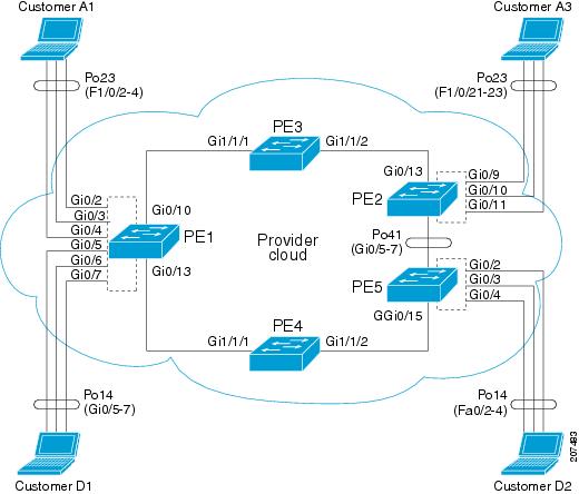
Configuration on Customer A1:
Switch #show etherchannel summaryFlags: D - down P - bundled in port-channelI - stand-alone s - suspendedH - Hot-standby (LACP only)R - Layer3 S - Layer2U - in use f - failed to allocate aggregatorM - not in use, minimum links not metu - unsuitable for bundlingw - waiting to be aggregatedd - default portNumber of channel-groups in use: 2Number of aggregators: 2Group Port-channel Protocol Ports------+-------------+-----------+-----------------------------------------------23 Po23(SU) PAgP (desirable) Fa1/0/2(P) Fa1/0/3(P) Fa1/0/4(P)Configuration on PE-1:
Switch (config)# interface GigabitEthernet0/2Switch (config-if)# switchport access vlan 4002Switch (config-if)# ethernet dot1ad uni s-portSwitch (config)# interface GigabitEthernet0/2Switch (config-if)# switchport access vlan 4002Switch (config-if)# switchport mode trunkSwitch (config)# interface GigabitEthernet0/3Switch (config-if)# switchport access vlan 4001Switch (config-if)# ethernet dot1ad uni s-portSwitch (config-if)# switchport trunk allowed vlan 4002Switch (config-if)# switchport vlan mapping default dot1ad-bundleSwitch (config-if)# Ethernet dot1ad uni c-portSwitch (config)# interface GigabitEthernet0/4Switch (config-if)# switchport access vlan 4003Switch (config-if)# ethernet dot1ad uni s-portSwitch (config)# interface GigabitEthernet0/10Switch (config-if)# switchport trunk allowed vlan 4001-4094Switch (config-if)# switchport mode trunkSwitch (config-if)# media-type sfpSwitch (config-if)# ethernet dot1ad nniConfiguration on PE-3
Switch (config)# interface GigabitEthernet1/1/1Switch (config-if)# switchport trunk allowed vlan 4001-4094Switch (config-if)# switchport mode trunkSwitch (config-if)# switchport trunk dot1q ethertype 88A8Switch (config-if)# udld port aggressiveSwitch (config-if)# ethernet dot1ad nniSwitch (config)# interface GigabitEthernet1/1/2Switch (config-if)# switchport trunk allowed vlan 4001-4094Switch (config-if)# switchport mode trunkSwitch (config-if)# switchport trunk dot1q ethertype 88A8Switch (config-if)# udld port aggressiveSwitch (config-if)# ethernet dot1ad nniConfiguration on PE-2
Switch (config)# interface GigabitEthernet0/9Switch (config-if)# switchport access vlan 4002Switch (config-if)# ethernet dot1ad uni s-portSwitch (config)# interface GigabitEthernet0/10Switch (config-if)# switchport access vlan 4001Switch (config-if)# ethernet dot1ad uni s-portSwitch (config)# interface GigabitEthernet0/11Switch (config-if)# switchport access vlan 4003Switch (config-if)# ethernet dot1ad uni s-portSwitch (config)# interface GigabitEthernet0/13Switch (config-if)# switchport trunk allowed vlan 4001-4094Switch (config-if)# switchport mode trunkSwitch (config-if)# ethernet dot1ad nniConfiguration on Customer A3
Switch (config)# interface Port-channel23Switch (config-if)# switchport trunk encapsulation dot1qSwitch (config-if)# switchport mode trunkSwitch (config)# interface FastEthernet1/0/21Switch (config-if)# switchport trunk encapsulation dot1qSwitch (config-if)# switchport mode trunkSwitch (config-if)# channel-protocol pagpSwitch (config-if)# channel-group 23 mode desirableSwitch (config)# interface FastEthernet1/0/22Switch (config-if)# switchport trunk encapsulation dot1qSwitch (config-if)# switchport mode trunkSwitch (config-if)# channel-protocol pagpSwitch (config-if)# channel-group 23 mode desirableSwitch (config-if)# interface FastEthernet1/0/23Switch (config-if)# switchport trunk encapsulation dot1qSwitch (config-if)# switchport mode trunkSwitch (config-if)# channel-protocol pagpSwitch (config-if)# channel-group 23 mode desirableConfiguration with 802.1ad C-UNI port on PE-2 and PE-3
Switch (config)# interface GigabitEthernet0/2Switch (config-if)# switchport access vlan 4002Switch (config-if)# switchport mode trunkSwitch (config-if)# switchport trunk allowed vlan 4002Switch (config-if)# switchport vlan mapping default dot1ad-bundle 4002Switch (config-if)# Ethernet dot1ad uni c-portSwitch (config)# interface GigabitEthernet0/3Switch (config-if)# switchport access vlan 4001Switch (config-if)# switchport mode trunkSwitch (config-if)# switchport trunk allowed vlan 4001Switch (config-if)# switchport vlan mapping default dot1ad-bundle 4001Switch (config-if)# Ethernet dot1ad uni c-portSwitch (config)# interface GigabitEthernet0/4Switch (config-if)# switchport access vlan 4003Switch (config-if)# switchport mode trunkSwitch (config-if)# switchport trunk allowed vlan 4003Switch (config-if)# switchport vlan mapping default dot1ad-bundle 4003Switch (config-if)# Ethernet dot1ad uni c-portThe configuration on other switches remains the same in the 802.1ad C-UNI scenario.
"Configuring Ethernet OAM, CFM, and E-LMI" Chapter—New Section
Configuring CFM on C-VLAN (Inner VLAN)
The previous implementation of IEEE 802.1ag CFM allows provisioning of maintenance points on the S-VLAN component. It does not allow monitoring or troubleshooting when QinQ is enabled on the provider-edge (PE) device. This release allows customers to provision maintenance intermediate points (MIPs) and Up maintenance endpoints (MEPs) on the C-VLAN (inner VLAN) component of QinQ or 802.1ad ports to provide visibility on the C-VLAN. In addition, some C-VLAN restrictions are removed and C-VLANs are now supported on 802.1q tunnel ports.
For more information about this feature and the supported commands, see:
http://www.cisco.com/en/US/docs/ios/cether/configuration/guide/ce_cfm-ieee_cvlan.html
The switch supports 802.1q-tunnel-port mode
Feature Support and Behavior
CFM S-VLAN component support:
•
Up MEPs use the port access VLAN ID (the outer tag or S-VLAN).
CFM frames sent and received by Up MEPs have a single VLAN tag, and the VLAN identifier is the port access VLAN ID (S-VLAN). Because the 802.1q tunnel interface marks the endpoint of the S-VLAN, the associated S-VLAN component should mark the endpoint of the CFM domain running over the S-VLAN space.
CFM C-VLAN component support:
•
Up MEPs use two tags: an outer tag with a VLAN ID that is the port access VLAN (S-VLAN) and an inner tag with a selected C-VLAN that is allowed through the 802.1q tunnel port. CFM frames sent and received by these Up MEPs are always double-tagged.
•
MIPs process CFM frames that are single-tagged when coming from the wire-side and double-tagged when coming from the relay-function side.
•
Port MEP frames are always sent untagged, even when the dot1q vlan native tag is enabled.
Supported maintenance points on 802.1q tunnels:
•
•
•
•
Note
Platform Restrictions and Limitations
•
–
–
–
•
–
–
–
•
•
–
–
–
–
–
–
–
–
–
–
"Supported MIBs" Appendix
The IEEE-compliant CFM MIB (IEEE CFM MIB) provides MIB support for IEEE 802.1ag compliant CFM (IEEE CFM) services. The IEEE CFM MIB can be used as a tool to trace paths, verify and manage connectivity, and detect faults in a network.
For information about the IEEE CFM MIB and the services it supports, see this URL:
http://www.cisco.com/en/US/docs/ios/cether/configuration/guide/ce_cfm-ieee_mib.html
"Unsupported Commands" Appendix
These IP unicast routing commands are now supported:
set tag (route-map configuration)
ip prefix-list (global configuration)
ip as-path access-list (global configuration)
These CGMP commands are not supported:
ip cgmp (interface configuration)
clear ip cgmp (privileged EXEC)
Updates to the Software Configuration Guide for Cisco IOS Release 12.2(52)SE
"Configuring IP Unicast Routing" Chapter
User Interface for VRF-Aware RADIUS
To configure VRF-Aware RADIUS, you must first enable AAA on a RADIUS server. This release supports the ip vrf forwarding vrf-name server-group configuration and the ip radius source-interface global configuration commands, as described in the Per VRF AAA Feature Guide at this URL:
http://www.cisco.com/en/US/docs/ios/12_2t/12_2t13/feature/guide/ftvrfaaa.html
"Configuring Ethernet OAM, CFM, and E-LMI" Chapter
•
The Service Diagnostics 2.0 C FM diagnostic scripts is part of the 12.2(52)SE release. The script is available for download at:
Refer to the Service Diagnostic 2.0 user guide at:
http://www.cisco.com/en/US/prod/collateral/iosswrel/ps6537/ps6555/ps9424/whitepaper_c11-566741.html
•
In the "Configuring the CFM Domain" section, Step 2 was to enter the ethernet cfm ieee global configuration command to configure the CFM version as IEEE 802.1ag.
This step is not required. If you are running Cisco IOS Release 12.2(52)SE, the CFM version is always 802.1ag and the command is automatically generated when you enable CFM.
"Configuring IEEE 802.1x Port-Based Authentication" Chapter
This section was added:
Common Session ID
Authentication manager uses a single session ID (referred to as a common session ID) for a client no matter which authentication method is used. This ID is used for all reporting purposes, such as the show commands and MIBs. The session ID appears with all per-session syslog messages.
The session ID includes:
•
•
•
This example shows how the session ID appears in the output of the show authentication command. The session ID in this example is 160000050000000B288508E5:
Switch# show authentication sessionsInterface MAC Address Method Domain Status Session IDFa4/0/4 0000.0000.0203 mab DATA Authz Success 160000050000000B288508E5This is an example of how the session ID appears in the syslog output. The session ID in this example is also160000050000000B288508E5:
1w0d: %AUTHMGR-5-START: Starting 'mab' for client (0000.0000.0203) on Interface Fa4/0/4
AuditSessionID 160000050000000B288508E5
1w0d: %MAB-5-SUCCESS: Authentication successful for client (0000.0000.0203) on Interface Fa4/0/4 AuditSessionID 160000050000000B288508E51w0d: %AUTHMGR-7-RESULT: Authentication result 'success' from 'mab' for client (0000.0000.0203) on Interface Fa4/0/4 AuditSessionID 160000050000000B288508E5The session ID is used by the NAD, the AAA server, and other report-analyzing applications to identify the client. The ID appears automatically. No configuration is required.
Updates to the Command Reference for Cisco IOS Release 12.2(54)SE
This platform-specific command was added for this release:
These commands were updated:
debug platform dot1ad
To enable debugging of IEEE 802.1ad tagging, use the debug platform dot1ad privileged EXEC command. To disable debugging, use the no form of the command.
debug platform dot1ad [error | events | receive | transmit]
no debug platform dot1ad [error | events | receive | transmit]
Syntax Description
error
Displays 802.1ad error messages.
events
Displays 802.1ad event debug messages.
receive
Displays 802.1ad receive debug messages.
transmit
Displays 802.1ad sent debug messages.
Defaults
Debugging is disabled.
Command Modes
Privileged EXEC
Command History
Usage Guidelines
The undebug platform dot1ad command is the same as the no debug platform dot1ad command.
When you enter debug platform dot1ad with no keywords, all 802.1ad debug messages appear.
Related Commands
rep block port
These usage guidelines were added:
There is no limit to the number of times that you can enter the rep block port id port-id vlan vlan-list interface configuration command. You can block an unlimited number, range, or sequence of VLANs.
When you use the rep block port id port-id vlan vlan-list interface configuration command on a Resilient Ethernet Protocol (REP) primary edge port to block a VLAN list and then use the same command to block another VLAN list on the same port, the second VLAN list does not replace the first VLAN list but is appended to the first VLAN list.
When you use the rep block port id port-id vlan vlan-list interface configuration command on a REP primary edge port to block a VLAN list on one port and then use the same command to block another VLAN list on another port, the original port number and VLAN list are overwritten.
show inventory
This usage guideline was added:
For the product identifier (PID) and version identifier (VID) of SFP modules, the output of the show inventory user EXEC command displays either the correct information or displays Unspecified for the PID and nothing for the VID if the SFP module does not have PID and VID information.
Updates to the System Message Guide
These messages were added to the system message guide:
Error Message    DOT1X-5-FAIL: Authentication failed for client ([chars]) on Interface
[chars] AuditSessionID [chars]
Explanation The authentication was unsuccessful. The first [chars] is the client ID, the second [chars] is the interface, and the third [chars] is the session ID.
Recommended Action No action is required.
Error Message    DOT1X-4-MEM_UNAVAIL: Memory was not available to perform the 802.1X
action. AuditSessionID [chars]
Explanation The system memory is not sufficient to perform the IEEE 802.1x authentication. [chars] is the session ID.
Recommended Action Reduce other system activity to reduce memory demands.
Error Message    %DOT1X-5-RESULT_OVERRIDE: Authentication result overridden for client
([chars]) on Interface [chars] AuditSessionID [chars]
Recommended Action The authentication result was overridden. The first [chars] is the client ID, the second [chars] is the interface, and the third [chars] is the session ID.
Explanation No action is required.
Error Message    DOT1X-5-SUCCESS: Authentication successful for client ([chars]) on
Interface [chars] AuditSessionID [chars]
Explanation Authentication was successful. The first [chars] is the client ID, the second [chars] is the interface, and the third [chars] is the session ID.
Recommended Action No action is required.
Error Message    DOT1X_SWITCH-5-ERR_ADDING_ADDRESS: Unable to add address [enet] on
[chars] AuditSessionID [chars]
Explanation The client MAC address could not be added to the MAC address table because the hardware memory is full or the address is a secure address on another port. This message might appear if IEEE 802.1x is enabled. [enet] is the client MAC address, the first [chars] is the interface, and the second [chars] is the session ID.
Recommended Action If the hardware memory is full, remove some of the dynamic MAC addresses. If the client address is on another port, remove it from that port.
Error Message    DOT1X_SWITCH-5-ERR_INVALID_PRIMARY_VLAN: Attempt to assign primary
VLAN [dec] to 802.1x port [chars] AuditSessionID [chars]
Explanation An attempt was made to assign a primary VLAN to an IEEE 802.1x port, which is not allowed. [dec] is the VLAN, the first [chars] is the port, and the second [chars] is the session ID.
Recommended Action Use a different VLAN.
Error Message    DOT1X_SWITCH-5-ERR_INVALID_SEC_VLAN: Attempt to assign invalid
secondary VLAN [dec] to PVLAN host 802.1x port [chars] AuditSessionID [chars]
Explanation An attempt was made to assign a nonsecondary VLAN to a private VLAN host IEEE 802.1x port. [dec] is the VLAN, the first [chars] is the port, and the second [chars] is the session ID.
Recommended Action Change the mode of the port so that it is no longer a PVLAN host port or use a valid secondary VLAN.
Error Message    DOT1X_SWITCH-5-ERR_PRIMARY_VLAN_NOT_FOUND: Attempt to assign VLAN
[dec], whose primary VLAN does not exist or is shutdown, to 802.1x port [chars]
AuditSessionID [chars]
Explanation An attempt was made to assign a private VLAN whose primary VLAN does not exist or is shut down. [dec] is the VLAN, the first [chars] is the port, and the second [chars] is the session ID.
Recommended Action Make sure the primary VLAN exists and is not shut down. Verify that the private VLAN is associated with a primary VLAN.
Error Message    DOT1X_SWITCH-5-ERR_SEC_VLAN_INVALID: Attempt to assign secondary VLAN
[dec] to non-PVLAN host 802.1x port [chars] AuditSessionID [chars]
Explanation An attempt was made to assign a secondary VLAN to a port that is not a private VLAN host port, which is not allowed. [dec] is the VLAN, the first [chars] is the port, and the second [chars] is the session ID.
Recommended Action Change the mode of the port so that it is configured as a private VLAN host port, or use a different VLAN that is not configured as a secondary VLAN.
Error Message    DOT1X_SWITCH-5-ERR_SPAN_DST_PORT: Attempt to assign VLAN [dec] to
802.1x port [chars], which is configured as a SPAN destination AuditSessionID
[chars]
Explanation An attempt was made to assign a VLAN to an IEEE 802.1x port that is configured as a Switched Port Analyzer (SPAN) destination port. [dec] is the VLAN, the first [chars] is the port, and the second [chars] is the session ID.
Recommended Action Change the SPAN configuration so that the port is no longer a SPAN destination port, or change the configuration so that no VLAN is assigned.
Error Message    DOT1X_SWITCH-5-ERR_VLAN_EQ_VVLAN: Data VLAN [dec] on port [chars]
cannot be equivalent to the Voice VLAN AuditSessionID [chars]
Explanation An attempt was made to assign a data VLAN to an IEEE 802.1x port that is the same as the voice VLAN. [dec] is the VLAN, the first [chars] is the port, and the second [chars] is the session ID.
Recommended Action Change either the voice VLAN or the IEEE 802.1x-assigned VLAN on the interface so that they are not the same.
Error Message    DOT1X_SWITCH-5-ERR_VLAN_INTERNAL: Attempt to assign internal VLAN
[dec] to 802.1x port [chars] AuditSessionID [chars]
Explanation An attempt was made to assign an invalid VLAN to an IEEE 802.1x port. The VLAN specified is used internally and cannot be assigned to this port. [dec] is the VLAN, the first [chars] is the port, and the second [chars] is the session ID.
Explanation Assign a different VLAN.
Error Message    DOT1X_SWITCH-5-ERR_VLAN_INVALID: Attempt to assign invalid VLAN [dec]
to 802.1x port [chars] AuditSessionID [chars]
Explanation An attempt was made to assign an invalid VLAN to an IEEE 802.1x port. The VLAN specified is out of range. [dec] is the VLAN, the first [chars] is the port, and the second [chars] is the session ID.
Recommended Action Update the configuration to use a valid VLAN.
Error Message    DOT1X_SWITCH-5-ERR_VLAN_NOT_FOUND: Attempt to assign non-existent or
shutdown VLAN [chars] to 802.1x port [chars] AuditSessionID [chars]
Explanation An attempt was made to assign a VLAN to an IEEE 802.1x port, but the VLAN was not found in the VLAN Trunking Protocol (VTP) database. [dec] is the VLAN, the first [chars] is the port, and the second [chars] is the session ID.
Recommended Action Make sure the VLAN exists and is not shutdown or use another VLAN.
Deleted System Messages
These messages were deleted from the system message guide:
Error Message    DOT1X-4-MEM_UNAVAIL: Memory was not available to perform the 802.1X
action.
Error Message DOT1X-5-SUCCESS: Authentication successful for client ([chars]) on Interface [chars]Error Message DOT1X_SWITCH-5-ERR_ADDING_ADDRESS: Unable to add address [enet] on [chars]Error Message DOT1X_SWITCH-5-ERR_INVALID_PRIMARY_VLAN: Attempt to assign primary VLAN [dec] to 802.1x port [chars]Error Message DOT1X_SWITCH-5-ERR_INVALID_SEC_VLAN: Attempt to assign invalid secondary VLAN [dec] to PVLAN host 802.1x port [chars]Error Message DOT1X_SWITCH-5-ERR_PRIMARY_VLAN_NOT_FOUND: Attempt to assign VLAN [dec], whose primary VLAN does not exist or is shutdown, to 802.1x port [chars]Error Message DOT1X_SWITCH-5-ERR_SEC_VLAN_INVALID: Attempt to assign secondary VLAN [dec] to non-PVLAN host 802.1x port [chars]Error Message DOT1X_SWITCH-5-ERR_SPAN_DST_PORT: Attempt to assign VLAN [dec] to 802.1x port [chars], which is configured as a SPAN destinationError Message DOT1X_SWITCH-5-ERR_VLAN_EQ_VVLAN: Data VLAN [dec] on port [chars] cannot be equivalent to the Voice VLAN.Error Message DOT1X_SWITCH-5-ERR_VLAN_INTERNAL: Attempt to assign internal VLAN [dec] to 802.1x port [chars]Error Message DOT1X_SWITCH-5-ERR_VLAN_INVALID: Attempt to assign invalid VLAN [dec] to 802.1x port [chars]Error Message DOT1X_SWITCH-5-ERR_VLAN_NOT_FOUND: Attempt to assign non-existent or shutdown VLAN [dec] to 802.1x port [chars]Error Message DOT1X_SWITCH-5-ERR_VLAN_ON_ROUTED_PORT: Dot1x cannot assign a VLAN [dec] to a routed port [chars]Error Message DOT1X_SWITCH-5-ERR_VLAN_PROMISC_PORT: Attempt to assign VLAN [dec] to promiscuous 802.1x port [chars]Error Message DOT1X_SWITCH-5-ERR_VLAN_RESERVED: Attempt to assign reserved VLAN [dec] to 802.1x port [chars]Error Message DOT1X_SWITCH-5-ERR_VLAN_RSPAN: Attempt to assign RSPAN VLAN [dec] to 802.1x port [chars]. 802.1x is incompatible with RSPANError Message SW_VLAN-4-VTP_USER_NOTIFICATION: VTP protocol user notification: [chars].Update to the Hardware Installation Guide
Installation Update
Cisco Ethernet Switches are equipped with cooling mechanisms, such as fans and blowers. However, these fans and blowers can draw dust and other particles, causing contaminant buildup inside the chassis, which can result in a system malfunction.
You must install this equipment in an environment as free as possible from dust and foreign conductive material (such as metal flakes from construction activities).
These standard provide guidelines for acceptable working environments and acceptable levels of suspended particulate matter:
•
•
•
Related Documentation
These documents provide information about the switch and are available from this Cisco.com site:
http://www.cisco.com/en/US/products/hw/switches/ps5532/tsd_products_support_series_home.html
•
•
•
•
•
•
•
Information about Cisco SFP, SFP+, and GBIC modules is available from this Cisco.com site:
http://www.cisco.com/en/US/products/hw/modules/ps5455/prod_installation_guides_list.html
SFP compatibility matrix documents are available from this Cisco.com site:
http://www.cisco.com/en/US/products/hw/modules/ps5455/products_device_support_tables_list.html
Obtaining Documentation, Obtaining Support, and Security Guidelines
For information on obtaining documentation, obtaining support, providing documentation feedback, security guidelines, and also recommended aliases and general Cisco documents, see the monthly What's New in Cisco Product Documentation, which also lists all new and revised Cisco technical documentation, at:
http://www.cisco.com/en/US/docs/general/whatsnew/whatsnew.html
This document is to be used in conjunction with the documents listed in the "Related Documentation" section.
CCDE, CCENT, CCSI, Cisco Eos, Cisco Explorer, Cisco HealthPresence, Cisco IronPort, the Cisco logo, Cisco Nurse Connect, Cisco Pulse, Cisco SensorBase, Cisco StackPower, Cisco StadiumVision, Cisco TelePresence, Cisco TrustSec, Cisco Unified Computing System, Cisco WebEx, DCE, Flip Channels, Flip for Good, Flip Mino, Flipshare (Design), Flip Ultra, Flip Video, Flip Video (Design), Instant Broadband, and Welcome to the Human Network are trademarks; Changing the Way We Work, Live, Play, and Learn, Cisco Capital, Cisco Capital (Design), Cisco:Financed (Stylized), Cisco Store, Flip Gift Card, and One Million Acts of Green are service marks; and Access Registrar, Aironet, AllTouch, AsyncOS, Bringing the Meeting To You, Catalyst, CCDA, CCDP, CCIE, CCIP, CCNA, CCNP, CCSP, CCVP, Cisco, the Cisco Certified Internetwork Expert logo, Cisco IOS, Cisco Lumin, Cisco Nexus, Cisco Press, Cisco Systems, Cisco Systems Capital, the Cisco Systems logo, Cisco Unity, Collaboration Without Limitation, Continuum, EtherFast, EtherSwitch, Event Center, Explorer, Follow Me Browsing, GainMaker, iLYNX, IOS, iPhone, IronPort, the IronPort logo, Laser Link, LightStream, Linksys, MeetingPlace, MeetingPlace Chime Sound, MGX, Networkers, Networking Academy, PCNow, PIX, PowerKEY, PowerPanels, PowerTV, PowerTV (Design), PowerVu, Prisma, ProConnect, ROSA, SenderBase, SMARTnet, Spectrum Expert, StackWise, WebEx, and the WebEx logo are registered trademarks of Cisco and/or its affiliates in the United States and certain other countries.
All other trademarks mentioned in this document or website are the property of their respective owners. The use of the word partner does not imply a partnership relationship between Cisco and any other company. (1002R)
© 2010 Cisco Systems, Inc. All rights reserved.
 Feedback