Configuring Layer 2 NAT
This document provides details about configuring Layer 2 Network Address Translation (NAT) on the Cisco Industrial Ethernet 2000 Series, Cisco Industrial Ethernet 4000 Series, Cisco Industrial Ethernet 4010 Series, and Cisco Industrial Ethernet 5000 Series switches.
Information About L2 Network Address Translation (NAT)
One-to-one (1:1) Layer 2 NAT is a service that allows the assignment of a unique public IP address to an existing private IP address (end device), so that the end device can communicate on both the private and public subnets. This service is configured in a NAT-enabled device and is the public “alias” of the IP address physically programmed on the end device. This is typically represented by a table in the NAT device.
Layer 2 NAT has two translation tables where private-to-public and public-to-private subnet translations can be defined. Layer 2 NAT is a hardware based implementation that provides the same high level of (bump-on-the-wire) wire-speed performance. This implementation also supports multiple VLANs through the NAT boundary for enhanced network segmentation.
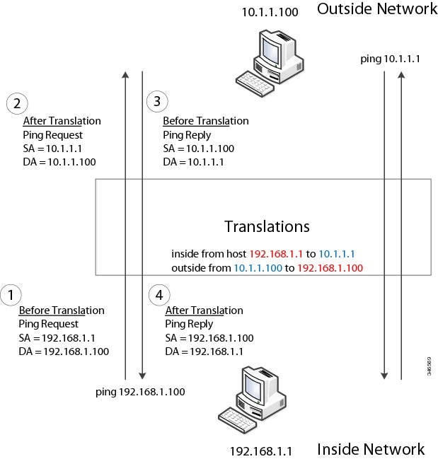
In the following example, Layer 2 NAT translates addresses between sensors on a 192.168.1.x network and a line controller on a 10.1.1.x network.
-
The 192.168.1.x network is the inside/internal IP address space and the 10.1.1.x network is the outside/external IP address space.
-
The sensor at 192.168.1.1 sends a ping request to the line controller by using an “inside” address, 192.168.1.100.
-
Before the packet leaves the internal network, Layer 2 NAT translates the source address (SA) to 10.1.1.1 and the destination address (DA) to 10.1.1.100.
-
The line controller sends a ping reply to 10.1.1.1.
-
When the packet is received on the internal network, Layer 2 NAT translates the source address to 192.168.1.100 and the destination address to 192.168.1.1.
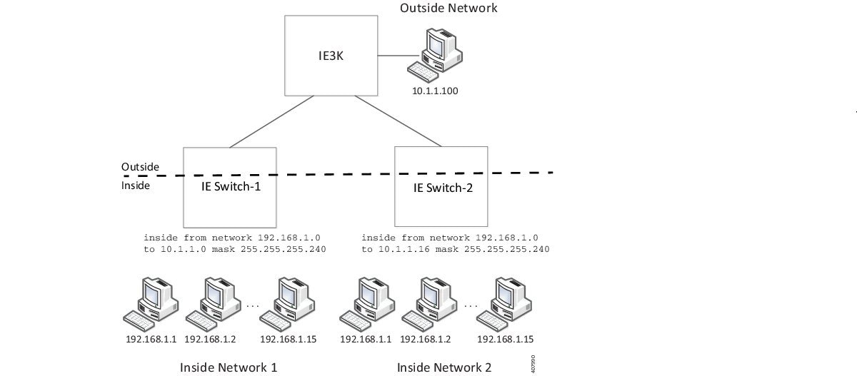
For large numbers of nodes, you can quickly enable translations for all devices in a subnet. In the scenario shown in the following figure, addresses from Inside Network 1 can be translated to outside addresses in the 10.1.1.0/28 subnet, and addresses from Inside Network 2 can be translated to outside addresses in the 10.1.1.16/28 subnet. All addresses in each subnet can be translated with one command.
The following figure shows an IE 5000 NAT configuration at the distribution level. In this example, the IE 5000 connects to devices in the private network through through Catalyst 2960 switches. The Catalyst switches at the access layer are not performing NAT. The IE5000 is performing L2 NAT on three interfaces for three different access switches. The IE switches are capable of supporting 128 instances of L2 NAT. In this example, only three of the 128 are shown. An entire subnet can be configured in a single L2 NAT instance.
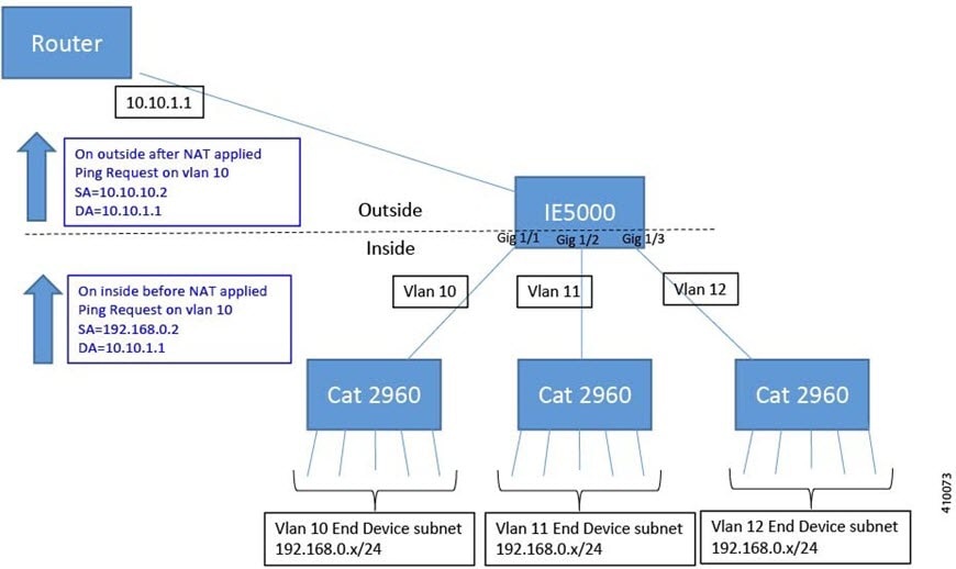
The IE 5000 NAT configuration for the diagram shown in the figure above is as follows:
Instance10:
 inside from network 192.168.0.0 to 10.10.10.0 mask 255.255.255.0
 outside from host 10.10.10.254 to 192.168.9.254 gateway
Instance11:
 inside from network 192.168.0.0 to 10.10.11.0 mask 255.255.255.0
 outside from host 10.10.11.254 to 192.168.9.254 gateway
Instance12:
 inside from network 192.168.0.0 to 10.10.12.0 mask 255.255.255.0
 outside from host 10.10.12.254 to 192.168.9.254 gateway
.
.
.
Interface vlan 10
 ip address 10.10.10.254 mask 255.255.255.0
Interface vlan 11
 ip address 10.10.11.254 mask 255.255.255.0
Interface vlan 12
Ip address 10.10.12.254 mask 255.255.255.0
Interface gig 1/1
 switchport access vlan 10
 l2nat instance10
Interface gig 1/2
 switchport access vlan 11
 l2nat instance11
Interface gig 1/3
 switchport access vlan 12
 l2nat instance12
Prerequisites
-
IE 2000—Layer 2 NAT is included in the Enhanced LAN Base feature set, available for Cisco IOS 15.0(2)EB or later.
-
IE 4000—Layer 2 NAT is included in the LAN Base feature set, available for Cisco IOS 15.2.(2)EA or later.
-
IE 4010—Layer 2 NAT is included in the LAN Base feature set, available for Cisco IOS 15.2(4)EC1 or later.
-
IE 5000—Layer 2 NAT is included in the LAN Base feature set, available for Cisco IOS 15.2(2)EB or later.
Guidelines and Limitations
-
Only IPv4 addresses can be translated.
-
Layer 2 NAT applies only to unicast traffic. You can permit or allow untranslated unicast traffic, multicast traffic, and IGMP traffic.
-
Layer 2 NAT does not support one-to-many and many-to-one IP address mapping.
-
Layer 2 NAT supports one-to-one mapping between external and internal IP addresses.
-
Layer 2 NAT cannot save on public IP addresses.
-
FTP traffic does not work because the embedded IP address is not translated.
-
If you configure a translation for a Layer 2 NAT host, do not configure it as a DHCP client.
-
Certain protocols such as ARP and ICMP do not work transparently across Layer 2 NAT but are “fixed up” by default. “Fixed up” means that changes are made to IP addresses embedded in the payload of IP packets for the protocols to work.
-
The interfaces that support NAT instance configurations are as follows:
-
IE2000: Gig 1/1 and Gig 1/2 (uplinks)
-
IE4000: Gig 1/1 - Gig 1/4 (uplinks)
-
IE4010: all interfaces are capable of supporting L2NAT. There is an interface group restriction on the IE4010. For interfaces in range Gig 1/1 - 6 and Gig 1/13 - 1/18 (12 leftmost interfaces), only 4 interfaces can simultaneously support NAT instances. Additionally, for the rightmost interfaces Gig 1/7 - 1/12, Gig 1/19 - 1/24, and Gig 1/25 - 1/28, only 4 interfaces can simultaneously support NAT instances.
-
IE5000: all interfaces are capable of supporting L2NAT. There is an interface group restriction on the IE5000. For interfaces in range Gig 1/1 - 1/6 and Gig 1/13 - 1/18 (12 leftmost interfaces), only 4 interfaces can simultaneously support NAT instances. Additionally, for the rightmost interfaces Gig 1/7 - 12 and Gig 1/19 - 1/24 and TenGig 1/1 - 1/4, only 4 interfaces can simultaneously support NAT instances.

Note
On IE4010 and IE5000 platforms, when you configure an L2NAT instance on the downlink ports (Gig 1/1 – Gig 1/24), you must configure the “inside” and “outside” IP addresses in the corresponding translation maps in reverse order compared to a translation map on uplink ports (Gig1/25, 28 or TenGig 1/1 – 1/4).
-
-
The downlink port can be VLAN, trunk, or Layer 2 channel.
-
You can configure 128 Layer 2 NAT instances on the switch.
-
Up to 128 VLANs are allowed to have Layer 2 NAT configuration.
-
The management interface is behind the Layer 2 NAT function. Therefore this interface should not be on the private network VLAN. If it is on the private network VLAN, assign an inside address and configure an inside translation.
-
Because L2NAT is designed to separate outside and inside addresses, we recommend that you do not configure addresses of the same subnet as both outside and inside addresses.
Default Settings
|
Feature |
Default Setting |
|---|---|
|
Permit or drop packets for unmatched traffic and traffic types that are not configured to be translated |
Drop all unmatched, multicast, and IGMP packets |
|
Protocol fixups |
Fixup is enabled for ARP and ICMP. |
Configuring Layer 2 NAT
You need to configure Layer 2 NAT instances that specify the address translations. Then you attach these instances to interfaces and VLANs. For unmatched traffic and traffic types that are not configured to be translated, you can choose to permit or drop the traffic. You can view detailed statistics about the packets sent and received (see Verifying Configuration).
To configure Layer 2 NAT, follow these steps. Refer to the examples in Basic Inside-to-Outside Communications Example and Duplicate IP Addresses Examplefor more details.
SUMMARY STEPS
- Enter global configuration mode:
- Create a new Layer 2 NAT instance:
- Translate an inside address to an outside address:
- Translate an outside address to an inside address:
- Fix the translation for ICMP and IGMP through NAT translation. By default, fixups for both ARP and ICMP are enabled, so this command is not normally needed unless you change the defaults.
- (Optional) Permit untranslated unicast traffic (it is dropped by default):
- Exit config-l2nat mode:
- Access interface configuration mode for the specified interface (uplink ports only on the IE 2000):
- Apply the specified Layer 2 NAT instance to a VLAN or VLAN range. If this parameter is missing, the Layer 2 NAT instance applies to the native VLAN.
- Exit interface configuration mode:
DETAILED STEPS
| Step 1 |
Enter global configuration mode: configure terminal |
||
| Step 2 |
Create a new Layer 2 NAT instance: l2nat instance instance_name After creating an instance, you use this same command to enter the sub-mode for that instance. |
||
| Step 3 |
Translate an inside address to an outside address: inside from [host | range | network ] original ip to translated ip [mask ] number | mask You can translate a single host address, a range of host addresses, or all of the addresses in a subnet. Translate the source address for outbound traffic and the destination address for inbound traffic. |
||
| Step 4 |
Translate an outside address to an inside address: outside from [host | range | network ] original ip to translated ip [mask ] number | mask [gateway ] You can translate a single host address, a range of host addresses, or all of the addresses in a subnet. Translate the destination address for outbound traffic and the source address for inbound traffic. The gateway keyword is optional and is used for Device Manager consumption only. |
||
| Step 5 |
Fix the translation for ICMP and IGMP through NAT translation. By default, fixups for both ARP and ICMP are enabled, so this command is not normally needed unless you change the defaults. fixup arp | icmp | all
|
||
| Step 6 |
(Optional) Permit untranslated unicast traffic (it is dropped by default): permit { multicast | igmp | all } |
||
| Step 7 |
Exit config-l2nat mode: exit |
||
| Step 8 |
Access interface configuration mode for the specified interface (uplink ports only on the IE 2000): interface interface-id |
||
| Step 9 |
Apply the specified Layer 2 NAT instance to a VLAN or VLAN range. If this parameter is missing, the Layer 2 NAT instance applies to the native VLAN. l2nat instance_name [vlan | vlan_range ] |
||
| Step 10 |
Exit interface configuration mode: end |
Verifying Configuration
To verify that Layer 2 NAT is working correctly and has connectivity, ping the translated IP address configured in the Layer 2 NAT translation maps and not the real IP addresses configured on the end devices. Use the show commands listed below to display Layer 2 NAT configuration.
|
Command |
Purpose |
|---|---|
|
show l2nat instance |
Displays the configuration details for a specified Layer 2 NAT instance. |
|
show l2nat interface |
Displays the configuration details for Layer 2 NAT instances on one or more interfaces. |
|
show l2nat statistics |
Displays the Layer 2 NAT statistics for all interfaces. |
|
show l2nat statistics interface |
Displays the Layer 2 NAT statistics for a specified interface. |
|
debug l2nat |
Enables showing real-time Layer 2 NAT configuration details when the configuration is applied. |
Basic Inside-to-Outside Communications Example
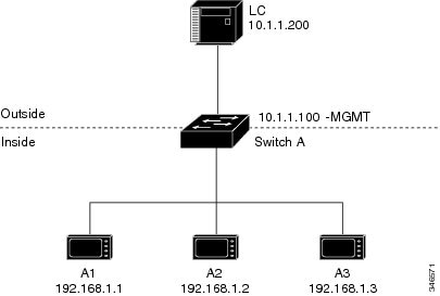
In this scenario, A1 needs to communicate with a logic controller (LC) that is directly connected to the uplink port. An Layer 2 NAT instance is configured to provide an address for A1 on the outside network (10.1.1.1) and an address for the LC on the inside network (192.168.1.250).
Now this communication can occur:
-
A1 sends an ARP request: SA: 192.168.1.1DA: 192.168.1.250.
-
Cisco Switch A fixes up the ARP request:SA:10.1.1.1DA: 10.1.1.200.
-
LC receives the request and learns the MAC Address of 10.1.1.1.
-
LC sends a response:SA: 10.1.1.200DA: 10.1.1.1.
-
Cisco Switch A fixes up the ARP response:SA: 192.168.1.250DA: 192.168.1.1.
-
A1 learns the MAC address for 192.168.1.250, and communication starts.
Note |
The management interface of the switch must be on a different VLAN from the inside network 192.168.1.x. |
The following table shows the configuration tasks for this scenario. The Layer 2 NAT instance is created, two translation entries are added, and the instance is applied to the interface. ARP fixups are enabled by default.
Note |
This example is based on the IE 2000 switch. For the IE 4000 and IE 5000 switches, the interface numbers may vary. |
|
Command |
Purpose |
|||
|---|---|---|---|---|
|
1. |
Switch# configure |
Enters global configuration mode. |
||
|
2. |
Switch(config)# l2nat instance A-LC |
Creates a new Layer 2 NAT instance called A-LC. |
||
|
3. |
Switch(config-l2nat)# inside from host 192.168.1.1 to 10.1.1.1 |
Translates A1’s inside address to an outside address. |
||
|
4. |
Switch(config-l2nat)# inside from host 192.168.1.2 to 10.1.1.2 |
Translates A2’s inside address to an outside address. |
||
|
5. |
Switch(config-l2nat)# inside from host 192.168.1.3 to 10.1.1.3 |
Translates A3’s inside address to an outside address. |
||
|
6. |
Switch(config-l2nat)# outside from host 10.1.1.200 to 192.168.1.250 |
Translates LC’s outside address to an inside address. |
||
|
7. |
Switch(config-l2nat)# exit |
Exits config-l2nat mode. |
||
|
8. |
Switch(config)# interface Gi1/1 |
Accesses interface configuration mode for the uplink port. |
||
|
9. |
Switch(config-if)# l2nat A-LC |
Applies this Layer 2 NAT instance to the native VLAN on this interface.
|
||
|
10. |
Switch# end |
Returns to privileged EXEC mode. |
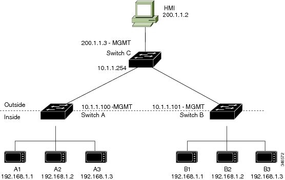
Duplicate IP Addresses Example
In this scenario, two machine nodes are preconfigured with addresses in the 192.168.1.x space. Layer 2 NAT translates these addresses to unique addresses on separate subnets of the outside network. In addition, for machine-to-machine communications, the Node A machines need unique addresses on the Node B space and the Node B machines need unique addresses in the Node A space.
-
Switch C needs an address in the 192.168.1.x space. When packets come into Node A or Node B, the 10.1.1.254 address of Switch C is translated to 192.168.1.254. When packets leave Node A or Node B, the 192.168.1.254 address of Switch C is translated to 10.1.1.254.
-
Node A and Node B machines need unique addresses in the 10.1.1.x space. For quick configuration and ease of use, the 10.1.1.x space is divided into subnets: 10.1.1.0, 10.1.1.16, 10.1.1.32, and so on. Each subnet can then be used for a different node. In this example, 10.1.1.16 is used for Node A, and 10.1.1.32 is used for Node B.
-
Node A and Node B machines need unique addresses to exchange data. The available addresses are divided into subnets. For convenience, the 10.1.1.16 subnet addresses for the Node A machines are translated to 192.168.1.16 subnet addresses on Node B. The10.1.1.32 subnet addresses for the Node B machines are translated to 192.168.1.32 addresses on Node A.
-
Machines have unique addresses on each network:
|
Node |
Address in Node A |
Address in Outside Network |
Address in Node B |
|---|---|---|---|
|
Switch A network address |
192.168.1.0 |
10.1.1.16 |
192.168.1.16 |
|
A1 |
192.168.1.1 |
10.1.1.17 |
192.168.1.17 |
|
A2 |
192.168.1.2 |
10.1.1.18 |
192.168.1.18 |
|
A3 |
192.168.1.3 |
10.1.1.19 |
192.168.1.19 |
|
Cisco Switch B network address |
192.168.1.32 |
10.1.1.32 |
192.168.1.0 |
|
B1 |
192.168.1.33 |
10.1.1.33 |
192.168.1.1 |
|
B2 |
192.168.1.34 |
10.1.1.34 |
192.168.1.2 |
|
B3 |
192.168.1.35 |
10.1.1.35 |
192.168.1.3 |
|
Switch C |
192.168.1.254 |
10.1.1.254 |
192.168.1.254 |
Table 2 shows the configuration tasks for Switch A. Table 3 shows the configuration tasks for Switch B.
Note |
This example is based on the IE 2000 switch. For the IE 4000 and IE 5000 switches, the interface numbers may vary. |
| Command | Purpose | |||
|---|---|---|---|---|
|
1. |
Switch# configure |
Enters global configuration mode. |
||
|
2. |
Switch(config)# l2nat instance A-Subnet |
Creates a new Layer 2 NAT instance called A-Subnet. |
||
|
3. |
Switch(config-l2nat)# inside from network 192.168.1.0 to 10.1.1.16 mask 255.255.255.240 |
Translates the Node A machines’ inside addresses to addresses in the 10.1.1.16 255.255.255.240 subnet. |
||
|
4. |
Switch(config-l2nat)# outside from host 10.1.1.254 to 192.168.1.254 |
Translates the outside address of Switch C to an inside address. |
||
|
5. |
Switch(config-l2nat)# outside from network 10.1.1.32 to 192.168.1.32 255.255.255.240 |
Translates the Node B machines’ outside addresses to their inside addresses. |
||
|
6. |
Switch(config-l2nat)# exit |
Exits config-l2nat mode. |
||
|
7. |
Switch(config)# interface Gi1/1 |
Accesses interface configuration mode for the uplink port. |
||
|
8. |
Switch(config-if)# l2nat A-Subnet |
Applies this Layer 2 NAT instance to the native VLAN on this interface.
|
||
|
9. |
Switch# end |
Returns to privileged EXEC mode. |
|
Command |
Purpose |
|||
|---|---|---|---|---|
|
1. |
Switch# configure |
Enters global configuration mode. |
||
|
2. |
Switch(config)# l2nat instance B-Subnet |
Creates a new Layer 2 NAT instance called B-Subnet. |
||
|
3. |
Switch(config-l2nat)# inside from network 192.168.1.0 to 10.1.1.32 255.255.255.240 |
Translates the Node B machines’ inside addresses to addresses in the 10.1.1.32 255.255.255.240 subnet. |
||
|
4. |
Switch(config-l2nat)# outside from host 10.1.1.254 to 192.168.1.254 |
Translates the outside address of Switch C to an inside address. |
||
|
5. |
Switch(config-l2nat)# outside from network 10.1.1.16 to 192.168.1.16 255.255.255.240 |
Translates the Node A machines’ outside addresses to their inside addresses. |
||
|
6. |
Switch(config-l2nat)# exit |
Exits config-l2nat mode. |
||
| 7. |
Switch(config)# interface Gi1/1 |
Accesses interface configuration mode for the uplink port. |
||
|
8. |
Switch(config-if)# l2nat name1 |
Applies this Layer 2 NAT instance to the native VLAN on this interface.
|
||
|
9. |
Switch# show l2nat instance name1 |
Shows the configuration details for the specified Layer 2 NAT instance. |
||
|
10. |
Switch# show l2nat statistics |
Shows Layer 2 NAT statistics. |
||
|
11. |
Switch# end |
Returns to privileged EXEC mode. |
Related Documents
Feature History
|
Feature Name |
Platform |
Release |
Feature Information |
|---|---|---|---|
|
Layer 2 NAT |
IE 5000 |
Cisco IOS Release 15.2(2)EB |
Initial support |
|
IE 4010 |
Cisco IOS Release 15.2(4)EC1 |
||
|
IE 4000 |
Cisco IOS Release 15.2.(2)EA |
||
|
IE 2000 |
Cisco IOS Release 15.0(2)EB |
 Feedback