Release Notes for the Cisco IE 3000 Switch, Cisco IOS Release 12.2(52)SE and Later
Available Languages
Table Of Contents
Release Notes for the Cisco IE 3000 Switch, Cisco IOS Release 12.2(52)SE and Later
Device Manager System Requirements
Finding the Software Version and Feature Set
Upgrading a Switch by Using the Device Manager or Network Assistant
Upgrading a Switch by Using the CLI
Recovering from a Software Failure
Cisco IOS Caveats Resolved in Cisco IOS Release 12.2(52)SE1
Cisco IOS Caveats Resolved in Cisco IOS Release 12.2(52)SE
Update to the Software Configuration Guide
Updates to the Getting Started Guide
Updates to the Regulatory Compliance and Safety Information for the Cisco IE 3000 Switch
Updates to the Hardware Installation Guide
Updates to the System Message Guide
Obtaining Documentation, Obtaining Support, and Security Guidelines
Release Notes for the Cisco IE 3000 Switch, Cisco IOS Release 12.2(52)SE and Later
February 16, 2010
Cisco IOS Release 12.2(52)SE1 runs on all Cisco IE 3000 switches.
These release notes include important information about Cisco IOS Release 12.2(52)SE and later, and any limitations, restrictions, and caveats that apply to the releases. Verify that these release notes are correct for your switch:
•
If you are installing a new switch, see the Cisco IOS release label on the rear panel of your switch.
•
•
For the complete list of Cisco IE 3000 switch documentation, see the "Related Documentation" section.
You can download the switch software from this site (registered Cisco.com users with a login password):
http://www.cisco.com/kobayashi/sw-center/sw-lan.shtml
Contents
This information is in the release notes:
•
•
System Requirements
The system requirements are described in these sections:
•
Hardware Supported
This section lists the hardware and SFP modules that the switch supports.
Switches and Modules
Table 1 lists the hardware supported on this release.
.
SFP Modules
These are the SFP modules that the switch supports:
.
Device Manager System Requirements
These sections describes the hardware and software requirements for using the device manager:
Hardware Requirements
Table 3 lists the minimum hardware requirements for running the device manager.
Table 3 Minimum Hardware Requirements
233 MHz minimum1
512 MB2
256
1024 x 768
Small
1 We recommend 1 GHz.
2 We recommend 1 GB DRAM.
Software Requirements
These are the supported operating systems and browsers for the device manager:
•
•
The device manager verifies the browser version when starting a session, and it does not require a plug-in.
Cluster Compatibility
You cannot create and manage switch clusters through the device manager. To create and manage switch clusters, use the command-line interface (CLI) or the Network Assistant application.
When creating a switch cluster or adding a switch to a cluster, follow these guidelines:
•
•
•
For additional information about clustering, see Getting Started with Cisco Network Assistant and Release Notes for Cisco Network Assistant (not orderable but available on Cisco.com), the software configuration guide, and the command reference.
CNA Compatibility
Cisco IOS 12.2(46)SE1 and later is only compatible with Cisco Network Assistant (CNA) 5.4 and later.

Note
You can download Cisco Network Assistant from this URL:
http://www.cisco.com/pcgi-bin/tablebuild.pl/NetworkAssistant
For more information about Cisco Network Assistant, see the Release Notes for Cisco Network Assistant on Cisco.com.
Upgrading the Switch Software
These are the procedures for downloading software. Before downloading software, read this section for important information:
•
•
•
•
Finding the Software Version and Feature Set
The Cisco IOS image is stored as a bin file in a directory that is named with the Cisco IOS release. A subdirectory contains the files needed for web management. The image is stored on the compact flash memory card.
You can use the show version privileged EXEC command to see the software version that is running on your switch. The second line of the display shows the version.
You can also use the dir filesystem: privileged EXEC command to see the directory names of other software images that you might have stored in flash memory.
Deciding Which Files to Use
The upgrade procedures in these release notes describe how to perform the upgrade by using a combined tar file. This file contains the Cisco IOS image file and the files needed for the embedded device manager. You must use the combined tar file to upgrade the switch through the device manager. To upgrade the switch through the command-line interface (CLI), use the tar file and the archive download-sw privileged EXEC command.
Table 4 lists the filenames for this software release.
If you download the IP services image and plan to use Layer 3 functionality, you must use the Switch Database Management (SDM) routing template. To see which template is currently active template, enter the show sdm prefer privileged EXEC command. If necessary, change the SDM template to the routing template by entering the sdm prefer routing global configuration command. You will be prompted to reload the switch to activate the new template.
Note
Archiving Software Images
Before upgrading your switch software, make sure that you have archived copies of the current Cisco IOS release and the Cisco IOS release to which you are upgrading. You should keep these archived images until you have upgraded all devices in the network to the new Cisco IOS image and until you have verified that the new Cisco IOS image works properly in your network.
Cisco routinely removes old Cisco IOS versions from Cisco.com. See Product Bulletin 2863 for more information:
http://www.cisco.com/en/US/products/sw/iosswrel/ps5187/prod_bulletin0900aecd80281c0e.html
You can copy the bin software image file on the flash memory to the appropriate TFTP directory on a host by using the copy flash: tftp: privileged EXEC command.
Note
You can also configure the switch as a TFTP server to copy files from one switch to another without using an external TFTP server by using the tftp-server global configuration command. For more information about the tftp-server command, see the "Basic File Transfer Services Commands" section of the Cisco IOS Configuration Fundamentals Command Reference, Release 12.2 at this URL:
Upgrading a Switch by Using the Device Manager or Network Assistant
You can upgrade switch software by using the device manager or Network Assistant. For detailed instructions, click Help.
Note
Upgrading a Switch by Using the CLI
This procedure is for copying the combined tar file to the switch. You copy the file to the switch from a TFTP server and extract the files. You can download an image file and replace or keep the current image.
Note
To download software, follow these steps:
Step 1
Step 2
http://www.cisco.com/kobayashi/sw-center/sw-lan.shtml
To download the image for a Cisco IE 3000 switch, click Cisco IE 3000 software. To obtain authorization and to download the cryptographic software files, click Cisco IE 3000 3DES Cryptographic Software.
Step 3
For more information, see the Cisco IE 3000 Switch Software Configuration Guide.Step 4
Step 5
Switch# ping tftp-server-addressFor more information about assigning an IP address and default gateway to the switch, see the software configuration guide for this release.
Step 6
Switch# archive download-sw /overwrite /reload
tftp:[[//location]/directory]/image-name.tar
The /overwrite option overwrites the software image in flash memory with the downloaded one.
The /reload option reloads the system after downloading the image unless the configuration has been changed and not saved.
For //location, specify the IP address of the TFTP server.
For /directory/image-name.tar, specify the directory (optional) and the image to download. Directory and image names are case sensitive.
This example shows how to download an image from a TFTP server at 198.30.20.19 and to overwrite the image on the switch:
Switch# archive download-sw /overwrite tftp://198.30.20.19/ies-lanbase-tar.122-52.SE1.tarYou can also download the image file from the TFTP server to the switch and keep the current image by replacing the /overwrite option with the /leave-old-sw option.
Recovering from a Software Failure
For additional recovery procedures, see the "Troubleshooting" chapter in the software configuration guide for this release.
Installation Notes
You can assign IP information to your switch by using these methods:
•
•
•
•
New Features
These sections describe the new supported hardware and the new and updated software features provided in this release:
New Hardware Features
There are no new hardware features for this release. For a list of all supported hardware, see the "Hardware Supported" section.
New Software Features
•
•
•
•
•
•
•
•
•
•
•
•
•
•
•
•
•
Limitations and Restrictions
You should review this section before you begin working with the switch. These are known limitations that will not be fixed, and there is not always a workaround. Some features might not work as documented, and some features could be affected by recent changes to the switch hardware or software.
This section contains these limitations:
Cisco IOS Limitations
These limitations apply to the Cisco IE 3000 switches:
•
•
•
Configuration
•
This problem occurs under these conditions:
–
–
–
The workaround is to reconfigure the static IP address. (CSCea71176 and CSCdz11708)
•
The workaround is to configure the port for 10 Mb/s and half duplex or to connect a hub or a nonaffected device to the switch. (CSCed39091)
•
The workaround is to enter the no switchport block unicast interface configuration command on that specific interface. (CSCee93822)
•
There is no workaround. This is a cosmetic error and does not affect the functionality of the switch. (CSCef59331)
•
High CPU utilization can also occur with other conditions, such as when debug messages are logged at a high rate to the console.
Use one of these workarounds:
–
–
–
•
The workaround is to configure aggressive UDLD. (CSCsh70244)
•
The workaround is to always enter a non zero value for the timeout value when you enter the boot host retry timeout timeout-value command. (CSCsk65142)
•
The workaround is to use the rep lsl-age-out timer interface configuration command to configure the REP LSL age timer for more than 1000 milliseconds (1 second). (CSCsz40613)
Ethernet
Traffic on EtherChannel ports is not perfectly load-balanced. Egress traffic on EtherChannel ports are distributed to member ports on load balance configuration and traffic characteristics like MAC or IP address. More than one traffic stream may map to same member ports based on hashing results calculated by the ASIC.
If this happens, uneven traffic distribution will happen on EtherChannel ports.
Changing the load balance distribution method or changing the number of ports in the EtherChannel can resolve this problem. Use any of these workarounds to improve EtherChannel load balancing:
•
•
•
•
For example, with load balance configured as dst-ip with 150 distinct incrementing destination IP addresses, and the number of ports in the EtherChannel set to either 2, 4, or 8, load distribution is optimal.(CSCeh81991)
IP
When the rate of received DHCP requests exceeds 2,000 packets per minute for a long time, the response time might be slow when you are using the console. The workaround is to use rate limiting on DHCP traffic to prevent a denial of service attack from occurring. (CSCeb59166)
Multicasting
•
•
•
–
–
There is no workaround. (CSCec20128)
•
The switchport block multicast interface configuration command is only applicable to non-IP multicast traffic.
There is no workaround. (CSCee16865)
•
–
–
The workaround is to enter the clear ip mroute privileged EXEC command on the interface. (CSCef42436)
After you configure a switch to join a multicast group by entering the ip igmp join-group group-address interface configuration command, the switch does not receive join packets from the client, and the switch port connected to the client is removed from the IGMP snooping forwarding table.
Use one of these workarounds:
–
–
•
The workaround is to enter the shutdown and the no shutdown interface configuration commands on the Fast Ethernet interface of a new IP phone that is attached to the service module port after the internal link is brought up. (CSCeh45465)
QoS
•
•
SPAN and RSPAN
•
Trunking
•
•
•
VLAN
•
The workaround is to reduce the number of VLANs or trunks. (CSCeb31087)
•
The workaround is to enter the switchport access vlan dynamic interface configuration command separately on each port. (CSCsi26392)
Device Manager Limitations
•
The workaround is to click Yes when you are prompted to accept the certificate. (CSCef45718)
•
The workaround is to manually reload the switch. (CSCsj88169)
Important Notes
Device Manager Notes
•
•
From Microsoft Internet Explorer:
1.
2.
3.
4.
5.
•
Beginning in privileged EXEC mode, follow these steps to configure the HTTP server interface:
•
If you change the HTTP port, you must include the new port number when you enter the IP address in the browser Location or Address field (for example, http://10.1.126.45:184 where 184 is the new HTTP port number). You should write down the port number through which you are connected. Use care when changing the switch IP information.
If you are not using the default method of authentication (the enable password), you need to configure the HTTP server interface with the method of authentication used on the switch.
Beginning in privileged EXEC mode, follow these steps to configure the HTTP server interface:
Open Caveats
•
When you configure an ACL and enter the access-group interface configuration command to apply it to an interface for web authentication, the output from the show epm session ip-address or show ip access_list interface interface-id privileged EXEC command does not show any web authentication filter ID.
There is no workaround.
•
On a switch running Cisco IOS release 12.2(46)SE, the output of the show interfaces privileged EXEC command shows 0 packets for port channel input and output rates.
The workaround is to reload the switch by entering the reload privileged EXEC command.
•
On switches running Cisco IOS release 12.2(50)SE3 running MAC authentication bypass with multidomain authentication (MDA, IP phones connected to a port might not be able to regain network connectivity in the VOICE domain if the session times out and all RADIUS servers are unreachable.
There is no workaround.
Resolved Caveats
Cisco IOS Caveats Resolved in Cisco IOS Release 12.2(52)SE1
•
In the STEP 7 network management tool, when you select the IE3000-STC module to see the software version, the Properties window shows the software revision as V12.2.46, instead of V12.2.52.
•
When you establish a Profinet session with the switch, the LLDP Chassis MAC field shows the MAC address of the egress port instead of the system MAC address.
Cisco IOS Caveats Resolved in Cisco IOS Release 12.2(52)SE
•
When an unsuccessful forward open request message is returned on the switch, the response does not contain the connection serial number, vendor ID, or vendor serial number information. Only the general and extended error codes are returned.
This problem only applies to unsuccessful forward open response messages.
The workaround is to enable the CIP debug command to determine the cause of the forward open failure.
•
The show cip object tcp/ip interface privileged EXEC command displays an old value for the domain name after it has been unconfigured with the no ip domain-name global configuration command.
The workaround is to ignore the domain name output of the show cip object tcp/ip interface privileged EXEC command.
•
When you configure PTP in forward mode by entering the ptp mode forward global configuration command, the PTP page in device manager breaks due to a parser error.
There is no workaround. No PTP information is displayed when PTP is in forward mode.
•
The device manager Legend incorrectly shows solid green for the Alarm and Setup LEDs in the Off state. The correct color of these LEDs in the Off state is solid black (dark).
There is no workaround.
•
When one power supply in a redundant pair fails, a CIP query continues to show that both supplies are present and okay. Redundant supplies are connected to the switch and one fails.
There is no workaround.
•
On switches running Cisco IOS Release 12.2(44)SE or 12.2(46)SE, when you enter the show mvr interface interface-id members privileged EXEC command to see status of an MVR port, an MVR member port that is not connected always shows as ACTIVE.
The workaround is to use the show mvr interface interface-id or the show mvr members privileged EXEC command. These command outputs show the correct status of an MVR port.
•
When you enter the mvr vlan vlan-id global configuration command to create an MVR VLAN and enable MVR on the switch by entering the mvr global configuration command, if you enter the show mvr interface interface-id members privileged EXEC command, the output shows the MVR groups on the interface. However, if you enable MVR first and then create the MVR VLAN, the MVR groups are not displayed correctly.
•
When VLAN-based quality of service (QoS) is enabled and then disabled on an interface by entering the mls qos vlan-based interface configuration command followed by the no version of the command, the port policy is not applied properly and could result in undefined behavior for packets matching the port policy.
The workaround is to remove the port policy by entering the no service-policy input policy-map-name interface configuration command and then reapply it to the interface.
•
If you enable 802.1Q native VLAN tagging by entering the vlan dot1q tag native global configuration command and then change the native VLAN ID on an ingress trunk port by entering the switchport trunk native vlan vlan-id interface command, untagged traffic is forwarded instead of being dropped.
The workaround is to use one of these methods:
–
–
•
If you repeatedly enter the show tech-support privileged EXEC command, the switch might leak memory and, in some cases, shut down.
The workaround is to reload the switch to clear the memory after repeated use of the show tech-support command.
•
The switch unexpectedly reloads when copying a configuration file from a remote server or from flash memory containing logging file flash:
The workaround is to enter the logging file flash:filename global configuration command to configure logging to flash instead of copying to flash.
•
When you have configured a login banner by entering the banner login c message c global configuration command and the switch reloads, the output of banner is missing a carriage return, making the format incorrect.
There is no workaround.
•
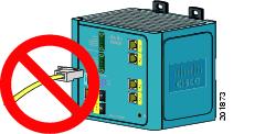
The link between a switch with a 100BaseFX-FE small form-factor pluggable (SFP) module and a connected device remains up when one of the fiber cables is removed.
The workaround is the use UniDirectional Link Detection (UDLD) in aggressive mode
•
When remote neighbors change, the LLDP MIB does not properly update the remote neighbors.
The workaround is to clear the LLDP table by entering the clear lldp table privileged EXEC command.
Documentation Updates
These sections provide updates to the product documentation:
•
•
•
•
•
Update to the Software Configuration Guide
The switch running Cisco IOS Release 12.2(50)SE does not support EnergyWise.
This section was added to the "Configuring IEEE 802.1x Port-Based Authentication" chapter:
Common Session ID
Authentication manager uses a single session ID (referred to as a common session ID) for a client no matter which authentication method is used. This ID is used for all reporting purposes, such as the show commands and MIBs. The session ID appears with all per-session syslog messages.
The session ID includes:
•
•
•
This example shows how the session ID appears in the output of the show authentication command. The session ID in this example is 160000050000000B288508E5:
Switch# show authentication sessionsInterface MAC Address Method Domain Status Session IDFa4/0/4 0000.0000.0203 mab DATA Authz Success 160000050000000B288508E5This is an example of how the session ID appears in the syslog output. The session ID in this example is also160000050000000B288508E5:
1w0d: %AUTHMGR-5-START: Starting 'mab' for client (0000.0000.0203) on Interface Fa4/0/4
AuditSessionID 160000050000000B288508E5
1w0d: %MAB-5-SUCCESS: Authentication successful for client (0000.0000.0203) on Interface Fa4/0/4 AuditSessionID 160000050000000B288508E51w0d: %AUTHMGR-7-RESULT: Authentication result 'success' from 'mab' for client (0000.0000.0203) on Interface Fa4/0/4 AuditSessionID 160000050000000B288508E5The session ID is used by the NAD, the AAA server, and other report-analyzing applications to identify the client. The ID appears automatically. No configuration is required.
Updates to the Getting Started Guide
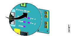
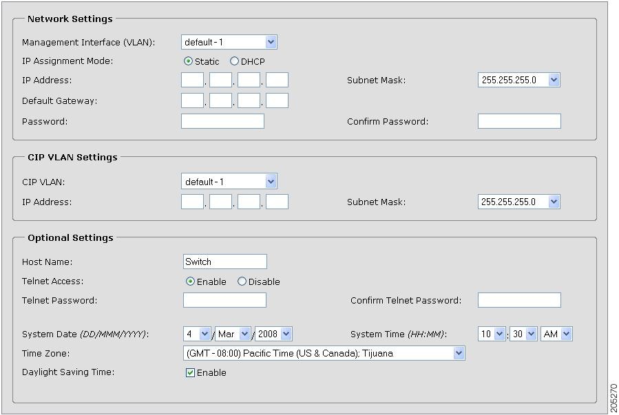
Express Setup
When you launch Express Setup, you are prompted for the switch password. Enter the default password, cisco. The switch ignores text in the username field. Before you complete and exit Express Setup, you must change the password from the default password, cisco.
In the "Running Express Setup" section of the Cisco IE 3000 Switch Getting Started Guide,
Steps 8 to 10 have changed.Running Express Setup:
To run Express Setup:
Warning Statement 1067
This warning statement has been removed from the Cisco IE 3000 Switch Getting Started Guide on Cisco.com.
Grounding the Switch
Step 6: Use a ratcheting torque screwdriver to tighten the ground screw and ring terminal lug to the switch front panel to 8.5 in-lb, the maximum recommended torque.
Wiring the DC Power Source
Step 6: Use a ratcheting torque flathead screwdriver to torque the power and relay connector captive screws (above the installed wire leads) to 2 in-lb, the maximum recommended torque.
Resetting the Switch
Follow these steps to return your switch to the factory default settings. These are reasons why you might want to reset the switch:
•
•
•

Caution
To reset the password on the switch:
1.
2.
3.
After the switch restarts, continue to run Express Setup.
Updates to the Regulatory Compliance and Safety Information for the Cisco IE 3000 Switch
Warning Statement 1067
Warning statement 1067 has been removed from the Regulatory Compliance and Safety Information for the Cisco IE 3000 Switch on Cisco.com.
Compliance Labels
Figure 1 Compliance Label for the Cisco IE 3000 Switch
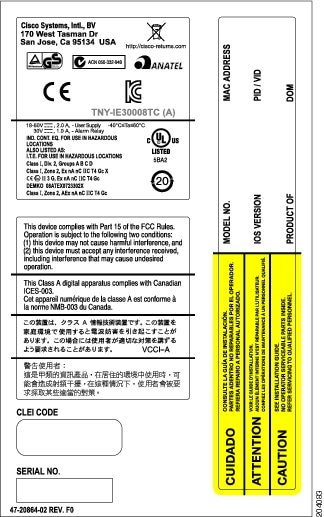
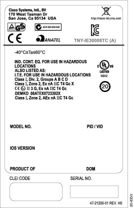
Figure 2 Compliance Label for the Cisco IE 3000 Switch Extension Module
Updates to the Hardware Installation Guide
This update is for the "Overview" chapter. These switches were added:
This update is for the "Technical Specifications" chapter.
The technical specifications listed in Table A-2 for the Cisco IE-3000-8TC and IE-3000-4TC switches also apply to the Cisco IE-3000-4TC-E and IE-3000-4TC-E switches.
Updates to the System Message Guide
This section contains the system message guide updates.
New System Messages
These messages were added to the system message guide:
Error Message    DOT1X-5-FAIL: Authentication failed for client ([chars]) on Interface
[chars] AuditSessionID [chars]
Explanation The authentication was unsuccessful. The first [chars] is the client ID, the second [chars] is the interface, and the third [chars] is the session ID.
Recommended Action No action is required.
Error Message    DOT1X-4-MEM_UNAVAIL: Memory was not available to perform the 802.1X
action. AuditSessionID [chars]
Explanation The system memory is not sufficient to perform the IEEE 802.1x authentication. [chars] is the session ID.
Recommended Action Reduce other system activity to reduce memory demands.
Error Message    DOT1X-5-SUCCESS: Authentication successful for client ([chars]) on
Interface [chars] AuditSessionID [chars]
Explanation Authentication was successful. The first [chars] is the client ID, the second [chars] is the interface, and the third [chars] is the session ID.
Recommended Action No action is required.
Error Message    DOT1X_SWITCH-5-ERR_ADDING_ADDRESS: Unable to add address [enet] on
[chars] AuditSessionID [chars]
Explanation The client MAC address could not be added to the MAC address table because the hardware memory is full or the address is a secure address on another port. This message might appear if IEEE 802.1x is enabled. [enet] is the client MAC address, the first [chars] is the interface, and the second [chars] is the session ID.
Recommended Action If the hardware memory is full, remove some of the dynamic MAC addresses. If the client address is on another port, remove it from that port.
Note
Error Message    DOT1X_SWITCH-5-ERR_INVALID_PRIMARY_VLAN: Attempt to assign primary
VLAN [dec] to 802.1x port [chars] AuditSessionID [chars]
Explanation An attempt was made to assign a primary VLAN to an IEEE 802.1x port, which is not allowed. [dec] is the VLAN, the first [chars] is the port, and the second [chars] is the session ID.
Recommended Action Use a different VLAN.
Note
Error Message    DOT1X_SWITCH-5-ERR_INVALID_SEC_VLAN: Attempt to assign invalid
secondary VLAN [dec] to PVLAN host 802.1x port [chars] AuditSessionID [chars]
Explanation An attempt was made to assign a nonsecondary VLAN to a private VLAN host IEEE 802.1x port. [dec] is the VLAN, the first [chars] is the port, and the second [chars] is the session ID.
Recommended Action Change the mode of the port so that it is no longer a PVLAN host port or use a valid secondary VLAN.
Note
Error Message    DOT1X_SWITCH-5-ERR_PRIMARY_VLAN_NOT_FOUND: Attempt to assign VLAN
[dec], whose primary VLAN does not exist or is shutdown, to 802.1x port [chars]
AuditSessionID [chars]
Explanation An attempt was made to assign a private VLAN whose primary VLAN does not exist or is shut down. [dec] is the VLAN, the first [chars] is the port, and the second [chars] is the session ID.
Recommended Action Make sure the primary VLAN exists and is not shut down. Verify that the private VLAN is associated with a primary VLAN.
Note
Error Message    DOT1X_SWITCH-5-ERR_SEC_VLAN_INVALID: Attempt to assign secondary VLAN
[dec] to non-PVLAN host 802.1x port [chars] AuditSessionID [chars]
Explanation An attempt was made to assign a secondary VLAN to a port that is not a private VLAN host port, which is not allowed. [dec] is the VLAN, the first [chars] is the port, and the second [chars] is the session ID.
Recommended Action Change the mode of the port so that it is configured as a private VLAN host port, or use a different VLAN that is not configured as a secondary VLAN.
Error Message    DOT1X_SWITCH-5-ERR_SPAN_DST_PORT: Attempt to assign VLAN [dec] to
802.1x port [chars], which is configured as a SPAN destination AuditSessionID
[chars]
Explanation An attempt was made to assign a VLAN to an IEEE 802.1x port that is configured as a Switched Port Analyzer (SPAN) destination port. [dec] is the VLAN, the first [chars] is the port, and the second [chars] is the session ID.
Recommended Action Change the SPAN configuration so that the port is no longer a SPAN destination port, or change the configuration so that no VLAN is assigned.
Error Message    DOT1X_SWITCH-5-ERR_VLAN_EQ_MDA_INACTIVE: Multi-Domain Authentication
cannot activate because Data and Voice VLANs are the same on port AuditSessionID
[chars]
Explanation Multi-Domain Authentication (MDA) host mode cannot start if the configured data VLAN on a port is the same as the voice VLAN. [chars] is the port session ID.
Recommended Action Change either the voice VLAN or the access VLAN on the interface so that they are not the same. MDA then starts.
Error Message    DOT1X_SWITCH-5-ERR_VLAN_EQ_VVLAN: Data VLAN [dec] on port [chars]
cannot be equivalent to the Voice VLAN AuditSessionID [chars]
Explanation An attempt was made to assign a data VLAN to an IEEE 802.1x port that is the same as the voice VLAN. [dec] is the VLAN, the first [chars] is the port, and the second [chars] is the session ID.
Recommended Action Change either the voice VLAN or the IEEE 802.1x-assigned VLAN on the interface so that they are not the same.
Error Message    DOT1X_SWITCH-5-ERR_VLAN_INTERNAL: Attempt to assign internal VLAN
[dec] to 802.1x port [chars] AuditSessionID [chars]
Explanation An attempt was made to assign an invalid VLAN to an IEEE 802.1x port. The VLAN specified is used internally and cannot be assigned to this port. [dec] is the VLAN, the first [chars] is the port, and the second [chars] is the session ID.
Explanation Assign a different VLAN.
Error Message    DOT1X_SWITCH-5-ERR_VLAN_INVALID: Attempt to assign invalid VLAN [dec]
to 802.1x port [chars] AuditSessionID [chars]
Explanation An attempt was made to assign an invalid VLAN to an IEEE 802.1x port. The VLAN specified is out of range. [dec] is the VLAN, the first [chars] is the port, and the second [chars] is the session ID.
Recommended Action Update the configuration to use a valid VLAN.
Error Message    DOT1X_SWITCH-5-ERR_VLAN_NOT_FOUND: Attempt to assign non-existent or
shutdown VLAN [chars] to 802.1x port [chars] AuditSessionID [chars]
Explanation An attempt was made to assign a VLAN to an IEEE 802.1x port, but the VLAN was not found in the VLAN Trunking Protocol (VTP) database. [dec] is the VLAN, the first [chars] is the port, and the second [chars] is the session ID.
Recommended Action Make sure the VLAN exists and is not shutdown or use another VLAN.
Deleted System Messages
These messages were deleted from the system message guide:
Error Message    DOT1X-4-MEM_UNAVAIL: Memory was not available to perform the 802.1X
action.
Explanation The system memory is not sufficient to perform the IEEE 802.1x authentication.
Recommended Action Reduce other system activity to reduce memory demands.
Error Message    DOT1X-5-SUCCESS: Authentication successful for client ([chars]) on
Interface [chars]
Explanation Authentication was successful. [chars] is the interface.
Recommended Action No action is required.
Error Message    DOT1X_SWITCH-5-ERR_ADDING_ADDRESS: Unable to add address [enet] on
[chars]
Explanation The client MAC address could not be added to the MAC address table because the hardware memory is full or the address is a secure address on another port. This message might appear if IEEE 802.1x is enabled. [enet] is the client MAC address, and [chars] is the interface.
Recommended Action If the hardware memory is full, remove some of the dynamic MAC addresses. If the client address is on another port, remove it from that port.
Note
Error Message    DOT1X_SWITCH-5-ERR_INVALID_PRIMARY_VLAN: Attempt to assign primary
VLAN [dec] to 802.1x port [chars]
Explanation An attempt was made to assign a primary VLAN to an IEEE 802.1x port, which is not allowed. [dec] is the VLAN, and [chars] is the port.
Recommended Action Use a different VLAN.
Note
Error Message    DOT1X_SWITCH-5-ERR_INVALID_SEC_VLAN: Attempt to assign invalid
secondary VLAN [dec] to PVLAN host 802.1x port [chars]
Explanation An attempt was made to assign a nonsecondary VLAN to a private VLAN host IEEE 802.1x port. [dec] is the VLAN, and [chars] is the port.
Recommended Action Change the mode of the port so that it is no longer a private VLAN host port, or use a valid secondary VLAN.
Note
Error Message    DOT1X_SWITCH-5-ERR_PRIMARY_VLAN_NOT_FOUND: Attempt to assign VLAN
[dec], whose primary VLAN does not exist or is shutdown, to 802.1x port [chars]
Explanation An attempt was made to assign a private VLAN whose primary VLAN does not exist or is shut down. [dec] is the VLAN, and [chars] is the port.
Recommended Action Make sure the primary VLAN exists and is not shut down. Verify that the private VLAN is associated with a primary VLAN.
Note
Error Message    DOT1X_SWITCH-5-ERR_SEC_VLAN_INVALID: Attempt to assign secondary VLAN
[dec] to non-PVLAN host 802.1x port [chars]
Explanation An attempt was made to assign a secondary VLAN to a port that is not a private VLAN host port, which is not allowed. [dec] is the VLAN, and [chars] is the port.
Recommended Action Change the mode of the port so that it is configured as a private VLAN host port, or use a different VLAN that is not configured as a secondary VLAN.
Error Message    DOT1X_SWITCH-5-ERR_SPAN_DST_PORT: Attempt to assign VLAN [dec] to
802.1x port [chars], which is configured as a SPAN destination
Explanation An attempt was made to assign a VLAN to an IEEE 802.1x port that is configured as a Switched Port Analyzer (SPAN) destination port. [dec] is the VLAN, and [chars] is the port.
Recommended Action Change the SPAN configuration so that the port is no longer a SPAN destination port, or change the configuration so that no VLAN is assigned.
Error Message    DOT1X_SWITCH-5-ERR_VLAN_EQ_MDA_INACTIVE: Multi-Domain Authentication
cannot activate because Data and Voice VLANs are the same on port [chars]
Recommended Action Multi-Domain Authentication (MDA) host mode cannot start if the configured data VLAN on a port is the same as the voice VLAN. [chars] is the port.
Recommended Action Change either the voice VLAN or the access VLAN on the interface so that they are not the same. MDA then starts.
Error Message    DOT1X_SWITCH-5-ERR_VLAN_EQ_VVLAN: Data VLAN [dec] on port [chars]
cannot be equivalent to the Voice VLAN.
Explanation An attempt was made to assign a data VLAN to an IEEE 802.1x port that is the same as the voice VLAN. [dec] is the VLAN, and [chars] is the port.
Recommended Action Change either the voice VLAN or the IEEE 802.1x-assigned VLAN on the interface so that they are not the same.
Error Message    DOT1X_SWITCH-5-ERR_VLAN_INTERNAL: Attempt to assign internal VLAN
[dec] to 802.1x port [chars]
Explanation An attempt was made to assign an invalid VLAN to an IEEE 802.1x port. The VLAN specified is used internally and cannot be assigned to this port. [dec] is the VLAN, and [chars] is the port.
Recommended Action Assign a different VLAN.
Error Message    DOT1X_SWITCH-5-ERR_VLAN_INVALID: Attempt to assign invalid VLAN [dec]
to 802.1x port [chars]
Explanation An attempt was made to assign an invalid VLAN to an IEEE 802.1x port. The VLAN specified is out of range. [dec] is the VLAN, and [chars] is the port.
Recommended Action Update the configuration to use a valid VLAN.
Error Message    DOT1X_SWITCH-5-ERR_VLAN_NOT_FOUND: Attempt to assign non-existent or
shutdown VLAN [dec] to 802.1x port [chars]
Explanation An attempt was made to assign a VLAN to an IEEE 802.1x port, but the VLAN was not found in the VLAN Trunking Protocol (VTP) database. [dec] is the VLAN, and [chars] is the port.
Recommended Action Make sure that the VLAN exists and is not shut down, or use another VLAN.
Error Message    DOT1X_SWITCH-5-ERR_VLAN_ON_ROUTED_PORT: Dot1x cannot assign a VLAN
[dec] to a routed port [chars]
Explanation An attempt was made to assign a VLAN to a supplicant on a routed port, which is not allowed. [dec] is the VLAN ID and [chars] is the port.
Recommended Action Either disable the VLAN assignment, or change the port type to a nonrouted port.
Error Message    DOT1X_SWITCH-5-ERR_VLAN_PROMISC_PORT: Attempt to assign VLAN [dec] to
promiscuous 802.1x port [chars]
Explanation An attempt was made to assign a VLAN to a promiscuous IEEE 802.1x port, which is not allowed. [dec] is the VLAN, and [chars] is the port.
Recommended Action Change the port mode so that it is no longer a promiscuous port, or change the configuration so that no VLAN is assigned.
Error Message    DOT1X_SWITCH-5-ERR_VLAN_RESERVED: Attempt to assign reserved VLAN
[dec] to 802.1x port [chars]
Explanation An attempt was made to assign an invalid VLAN to an IEEE 802.1x port. The VLAN specified is a reserved VLAN and cannot be assigned to this port. [dec] is the VLAN, and [chars] is the port.
Recommended Action Assign a different VLAN.
Error Message    DOT1X_SWITCH-5-ERR_VLAN_RSPAN: Attempt to assign RSPAN VLAN [dec] to
802.1x port [chars]. 802.1x is incompatible with RSPAN
Explanation This message means that remote SPAN should not be enabled on a VLAN with IEEE 802.1x-enabled. [dec] is the VLAN, and [chars] is the port.
Recommended Action Either disable remote SPAN configuration on the VLAN, or disable IEEE 802.1x on all the ports in this VLAN.
Related Documentation
These documents provide complete information about the Cisco IE 3000 switches and are available at Cisco.com:
http://www.cisco.com/en/US/products/ps9703/tsd_products_support_series_home.html
•
•
•
•
•
For other information about related products, see these documents:
•
•
•
These SFP module installation notes are available from this Cisco.com site:
http://www.cisco.com/en/US/products/hw/modules/ps5455/prod_installation_guides_list.html
•
•
These compatibility matrix documents are available from this Cisco.com site:
http://www.cisco.com/en/US/products/hw/modules/ps5455/products_device_support_tables_list.html
•
•
Obtaining Documentation, Obtaining Support, and Security Guidelines
For information on obtaining documentation, submitting a service request, and gathering additional information, see the monthly What's New in Cisco Product Documentation, which also lists all new and revised Cisco technical documentation, at:
http://www.cisco.com/en/US/docs/general/whatsnew/whatsnew.html
Subscribe to the What's New in Cisco Product Documentation as a Really Simple Syndication (RSS) feed and set content to be delivered directly to your desktop using a reader application. The RSS feeds are a free service and Cisco currently supports RSS version 2.0.
This document is to be used in conjunction with the documents listed in the "Related Documentation" section.
Cisco and the Cisco Logo are trademarks of Cisco Systems, Inc. and/or its affiliates in the U.S. and other countries. A listing of Cisco's trademarks can be found at www.cisco.com/go/trademarks. Third party trademarks mentioned are the property of their respective owners. The use of the word partner does not imply a partnership relationship between Cisco and any other company. (1005R)
© 2009-2010 Cisco Systems, Inc. All rights reserved.

 Feedback