- Preface
- Introduction: Using the Command-Line Interface
- aaa accounting dot1x to ipv6 mld snooping vlan
- l2nat to setup express
- show access-lists to vtp primary
- Switch Bootloader Commands on the IE 2000 Switch
- debug authentication to debug vqpc
- Cisco IE 2000 Switch Show Platform Commands
- Acknowledgments for Open-Source Software
Cisco IE 2000 Switch Command Reference Cisco IOS Release 15.0(2)EB
Bias-Free Language
The documentation set for this product strives to use bias-free language. For the purposes of this documentation set, bias-free is defined as language that does not imply discrimination based on age, disability, gender, racial identity, ethnic identity, sexual orientation, socioeconomic status, and intersectionality. Exceptions may be present in the documentation due to language that is hardcoded in the user interfaces of the product software, language used based on RFP documentation, or language that is used by a referenced third-party product. Learn more about how Cisco is using Inclusive Language.
- Updated:
- April 3, 2013
Chapter: l2nat to setup express
- l2nat
- l2nat instance
- lacp port-priority
- lacp system-priority
- link-diag error-rate
- link state group
- link state track
- location (global configuration)
- location (interface configuration)
- logging event
- logging file
- mab request format attribute 32
- mac access-group
- mac access-list extended
- mac address-table aging-time
- mac address-table learning vlan
- mac address-table move update
- mac address-table notification
- mac address-table static
- mac address-table static drop
- macro apply
- macro description
- macro description
- macro global
- macro global description
- macro name
- match (access-map configuration)
- match (class-map configuration)
- mdix auto
- media-type rj45
- mls qos
- mls qos aggregate-policer
- mls qos cos
- mls qos dscp-mutation
- mls qos map
- mls qos queue-set output buffers
- mls qos queue-set output threshold
- mls qos rewrite ip dscp
- mls qos srr-queue input bandwidth
- mls qos srr-queue input buffers
- mls qos srr-queue input cos-map
- mls qos srr-queue input dscp-map
- mls qos srr-queue input priority-queue
- mls qos srr-queue input threshold
- mls qos srr-queue output cos-map
- mls qos srr-queue output dscp-map
- mls qos trust
- mls qos vlan-based
- monitor session
- mvr (global configuration)
- mvr (interface configuration)
- network-policy
- network-policy profile (global configuration)
- network-policy profile (network-policy configuration)
- nmsp
- nmsp attachment suppress
- outside from
- pagp learn-method
- pagp port-priority
- permit (ARP access-list configuration)
- permit (config-l2nat configuration)
- permit (MAC access-list configuration)
- police
- police aggregate
- policy-map
- port-channel load-balance
- power-supply dual
- priority-queue
- profinet
- psp
- ptp (global configuration)
- ptp (interface configuration)
- queue-set
- radius-server dead-criteria
- radius-server host
- rcommand
- remote-span
- renew ip dhcp snooping database
- rep admin vlan
- rep block port
- rep lsl-age-timer
- rep preempt delay
- rep preempt segment
- rep segment
- rep stcn
- reserved-only
- rmon collection stats
- sdm prefer
- service password-recovery
- service-policy
- set
- setup
- setup express
l2nat
To apply an Layer 2 NAT instance to one or more VLANs on a selected interface, enter the l2nat command in interface configuration mode.
Enter the no form of this command to remove an Layer 2 NAT instance from a VLAN or VLAN range.
l2nat instance_name [ vlan | vlan_range ]
no l2nat instance_name [ vlan | vlan_range ]
Syntax Description
Command Default
Command Modes
Command History
|
|
|
|---|---|
Usage Guidelines
- The default VLAN is the native VLAN.
- If the same instance needs to be applied to untagged and tagged traffic (in case of native VLAN), you need to explicitly apply the instance to both VLANs.
- You can only have one Layer 2 NAT instance per VLAN, but you can apply the same instance to multiple VLANs to reuse the same translations.
- This command is allowed only on Gigabit uplink interfaces.
- If you have configured two uplink ports in an EtherChannel and you subsequently apply an instance to one port, the same instance is applied to the other port. In the statistics, the numbers from both ports are combined and are reported for the EtherChannel.
- If ports are configured in ring mode, you will need to apply the same instances to the same VLAN/interface combinations. Statistics are reported individually for each uplink port.
Examples
This example shows how to apply the instance named Instance1 to VLAN 10.
This example applies an instance to the native VLAN:
Related Commands
l2nat instance
To create an Layer 2 NAT instance or to enter the submode to configure an Layer 2 NAT instance, use the l2nat instance command in global configuration mode. Use the no form of this command to remove an Layer 2 NAT instance.
no l2nat instance instance_name
Syntax DescriptionS
Command Default
Command Modes
Command History
|
|
|
|---|---|
Usage Guidelines
Examples
This example shows how to create a new l2nat instance named Instance1. This same command can then be used to enter the submode for this instance.
This example shows how to remove an l2nat instance named Instance1.
Related Commands
lacp port-priority
To configure the port priority for the Link Aggregation Control Protocol (LACP), use the lacp port-priority command in interface configuration mode. Use the no form of this command to return to the default setting.
Syntax Description
Command Default
Command Modes
Command History
|
|
|
|---|---|
Usage Guidelines
The lacp port-priority interface configuration command determines which ports are bundled and which ports are put in hot-standby mode when there are more than eight ports in an LACP channel group.
An LACP channel group can have up to 16 Ethernet ports of the same type. Up to eight ports can be active, and up to eight ports can be in standby mode.
In port-priority comparisons, a numerically lower value has a higher priority: When there are more than eight ports in an LACP channel group, the eight ports with the numerically lowest values (highest priority values) for LACP port priority are bundled into the channel group, and the lower-priority ports are put in hot-standby mode. If two or more ports have the same LACP port priority (for example, they are configured with the default setting of 65535), an internal value for the port number determines the priority.

Note![]() The LACP port priorities are only effective if the ports are on the switch that controls the LACP link. See the lacp system-priority global configuration command for determining which switch controls the link.
The LACP port priorities are only effective if the ports are on the switch that controls the LACP link. See the lacp system-priority global configuration command for determining which switch controls the link.
Use the show lacp internal privileged EXEC command to display LACP port priorities and internal port number values.
For information about configuring LACP on physical ports, see the “Configuring EtherChannels” chapter in the software configuration guide for this release.
Examples
This example shows how to configure the LACP port priority on a port:
You can verify your settings by entering the show lacp [ channel-group-number ] internal privileged EXEC command.
Related Commands
|
|
|
|---|---|
show lacp [ channel-group-number ] internal |
Displays internal information for all channel groups or for the specified channel group. |
lacp system-priority
To configure the system priority for the Link Aggregation Control Protocol (LACP), use the lacp system-priority command in global configuration mode. Use the no form of this command to return to the default setting.
Syntax Description
Command Default
Command Modes
Command History
|
|
|
|---|---|
Usage Guidelines
The lacp system-priority command determines which switch in an LACP link controls port priorities.
An LACP channel group can have up to 16 Ethernet ports of the same type. Up to eight ports can be active, and up to eight ports can be in standby mode. When there are more than eight ports in an LACP channel group, the switch on the controlling end of the link uses port priorities to determine which ports are bundled into the channel and which ports are put in hot-standby mode. Port priorities on the other switch (the noncontrolling end of the link) are ignored.
In priority comparisons, numerically lower values have higher priority. Therefore, the system with the numerically lower value (higher priority value) for LACP system priority becomes the controlling system. If both switches have the same LACP system priority (for example, they are both configured with the default setting of 32768), the LACP system ID (the switch MAC address) determines which switch is in control.
The lacp system-priority command applies to all LACP EtherChannels on the switch.
Use the show etherchannel summary privileged EXEC command to see which ports are in the hot-standby mode (denoted with an H port-state flag in the output display).
For more information about configuring LACP on physical ports, see the “Configuring EtherChannels” chapter in the software configuration guide for this release.
Examples
This example shows how to set the LACP system priority:
Related Commands
|
|
|
|---|---|
show lacp sys-id |
link-diag error-rate
To configure the window size for the link diagnostic feature, use the link-diag error-rate command in global configuration mode.
link-diag error-rate (window-size { seconds })
Syntax Description
Specifies the link diagnostics error rate sliding-window duration in error-rate calculations; the duration range is from 5 to 600 seconds. |
Command Default
Command Modes
Command History
|
|
|
|---|---|
Usage Guidelines
The error rate is calculated based on a sliding window of time. For a given window size, the number of error packets and the total number of packets is sampled five equally spaced times within the window duration. The reported error rate is the average of the five samples, which allows the window to slide (or update) by a duration of one-fifth its size each time it is updated. The window size is configurable in seconds, and the window size must be a multiple of 5 seconds. The corresponding sample rate for the default window is one sample per minute. As a consequence, after every instance where the window size is changed, the reported error rate is not accurate until one window size duration has passed.
The counters used in the calculation are obtained from the platform counters using the show interface counter command. Reported packet errors for the receive direction include “alignment error,” “FCS error,” and “symbol error” frame error types. Reported packet errors for the transmit direction include “excessive collision” and “excessive defer” frame error types.
Examples
This example shows how to set the link-diag error-rate window size to 5 seconds:
Related Commands
|
|
|
|---|---|
link state group
To configure a port as a member of a link-state group, use the link state group command in interface configuration mode. Use the no form of this command to remove the port from the link-state group.
link state group [ number ] { upstream | downstream }
no link state group [ number ] { upstream | downstream }
Syntax Description
Command Default
Command Modes
Command History
|
|
|
|---|---|
Usage Guidelines
Use the link state group interface configuration command to configure a port as an upstream or downstream interface for the specified link-state group. If the group number is omitted, the default group number is 1.
To enable link-state tracking, create a link-state group, and specify the interfaces that are assigned to the link-state group. An interface can be an aggregation of ports (an EtherChannel), a single physical port in access or trunk mode, or a routed port. In a link-state group, these interfaces are bundled together. The downstream interfaces are bound to the upstream interfaces. Interfaces connected to servers are referred to as downstream interfaces, and interfaces connected to distribution switches and network devices are referred to as upstream interfaces.
For more information about the interactions between the downstream and upstream interfaces, see the “Configuring EtherChannels and Link-State Tracking” chapter of the software configuration guide for this release.
Examples
This example shows how to configure the interfaces as upstream in group 2 :
You can verify your settings by entering the show running-config privileged EXEC command.
Related Commands
|
|
|
|---|---|
Displays the current operating configuration. For syntax information, see the Cisco IOS Software Command Reference, Release 15.0. |
link state track
To enable a link-state group, use the link state track command in user EXEC mode. Use the no form of this command to disable a link-state group.
no link state track [ number ]
Syntax Description
(Optional) The link-state group number. The group number can be 1 to 6. The default is 1. |
Command Default
Command Modes
Command History
|
|
|
|---|---|
Usage Guidelines
Use the link state track global configuration command to enable a link-state group.
Examples
This example shows how enable link-state group 2:
You can verify your settings by entering the show running-config privileged EXEC command.
Related Commands
|
|
|
|---|---|
Displays the current operating configuration. For syntax information, see the Cisco IOS Software Command Reference, Release 15.0. |
location (global configuration)
To configure location information for an endpoint, use the location command in global configuration mode. Use the no form of this command to remove the location information.
location { admin-tag string | civic-location identifier id | elin-location string identifier id}
no location { admin-tag string | civic-location identifier id | elin-location string identifier id}
Syntax Description
Command Default
Command Modes
Command History
|
|
|
|---|---|
Usage Guidelines
After entering the location civic-location identifier id global configuration command, you enter civic location configuration mode. In this mode, you can enter the civic location and the postal location information.
The civic-location identifier must not exceed 250 bytes.
Use the no lldp med-tlv-select location information interface configuration command to disable the location TLV. The location TLV is enabled by default. For more information, see the “Configuring LLDP and LLDP-MED” chapter of the software configuration guide for this release.
Examples
This example shows how to configure civic location information on the switch:
Switch(config-civic)# number 3550
Switch(config-civic)# primary-road-name "Cisco Way"
Switch(config-civic)# city "San Jose"
Switch(config-civic)# state CA
Switch(config-civic)# building 19
Switch(config-civic)# room C6
Switch(config-civic)# county "Santa Clara"
Switch(config-civic)# country US
Switch(config-civic)# end
This example shows how to configure the emergency location information on the switch:
You can verify your settings by entering the show location elin privileged EXEC command.
Related Commands
|
|
|
|---|---|
location (interface configuration)
To enter location information for an interface, use the location command in interface mode. Use the no form of this command to remove the interface location information.
location { additional-location-information word | civic-location-id id | elin-location-id id}
no location { additional-location-information word | civic-location-id id | elin-location-id id}
Syntax Description
Command Default
Command Modes
Command History
|
|
|
|---|---|
Usage Guidelines
After entering the location civic-location-id id interface configuration command, you enter civic location configuration mode. In this mode, you can enter the additional location information.
Examples
This example shows how to enter civic location information for an interface:
This example shows how to enter emergency location information for an interface:
Related Commands
|
|
|
|---|---|
logging event
To enable notification of interface link status changes, use the logging event command in interface configuration mode. Use the no form of this command to disable notification.
logging event { bundle-status | link-status | spanning-tree | status | trunk status }
no logging event { bundle-status | link-status | spanning-tree | status | trunk status }
Syntax Description
Enables notification of spanning-tree state change messages. |
|
Command Default
Command Modes
Command History
|
|
|
Examples
This example shows how to enable spanning-tree logging:
logging file
To set logging file parameters, use the logging file command in global configuration mode. Use the no form of this command to return to the default setting.
logging file filesystem : filename [ max-file-size | nomax [ min-file-size ]] [ severity-level-number | type ]
no logging file filesystem: filename [ severity-level-number | type ]
Syntax Description
Command Default
The minimum file size is 2048 bytes; the maximum file size is 4096 bytes.
The default severity level is 7 (debugging messages and numerically lower levels).
Command Modes
Command History
|
|
|
|---|---|
Usage Guidelines
The log file is stored in ASCII text format in an internal buffer on the switch. You can access logged system messages by using the switch command-line interface (CLI) or by saving them to a properly configured syslog server. If the switch fails, the log is lost unless you had previously saved it to flash memory by using the logging file flash: filename global configuration command.
After saving the log to flash memory by using the logging file flash: filename global configuration command, you can use the more flash: filename privileged EXEC command to display its contents.
The command rejects the minimum file size if it is greater than the maximum file size minus 1024; the minimum file size then becomes the maximum file size minus 1024.
Specifying a level causes messages at that level and numerically lower levels to be displayed.
Examples
This example shows how to save informational log messages to a file in flash memory:
You can verify your setting by entering the show running-config privileged EXEC command.
Related Commands
|
|
|
|---|---|
Displays the running configuration on the switch. For syntax information, see the Cisco IOS Software Command Reference, Release 15.0. |
mab request format attribute 32
To enable VLAN ID-based MAC authentication on a switch, use the mab request format attribute 32 command in global configuration mode. Use the no form of this command to return to the default setting.
mab request format attribute 32 vlan access-vlan
no mab request format attribute 32 vlan access-vlan
Syntax Description
Command Default
Command Modes
Command History
|
|
|
|---|---|
Usage Guidelines
Use this command to allow a RADIUS server to authenticate a new user based on the host MAC address and VLAN.
Use this command on networks with the Microsoft IAS RADIUS server. The Cisco ACS ignores this command.
Examples
This example shows how to enable VLAN-ID based MAC authentication on a switch:
Related Commands
mac access-group
To apply a MAC access control list (ACL) to a Layer 2 interface, use the mac access-group command in interface configuration mode. Use the no form of this command to remove all MAC ACLs or the specified MAC ACL from the interface. You create the MAC ACL by using the mac access-list extended global configuration command.
Syntax Description
Specifies that the ACL is applied in the ingress direction. Outbound ACLs are not supported on Layer 2 interfaces. |
Command Default
Command Modes
Interface configuration (Layer 2 interfaces only)
Command History
|
|
|
|---|---|
Usage Guidelines
You can apply MAC ACLs only to ingress Layer 2 interfaces. You cannot apply MAC ACLs to Layer 3 interfaces.
On Layer 2 interfaces, you can filter IP traffic by using IP access lists and non-IP traffic by using MAC access lists. You can filter both IP and non-IP traffic on the same Layer 2 interface by applying both an IP ACL and a MAC ACL to the interface. You can apply no more than one IP access list and one MAC access list to the same Layer 2 interface.
If a MAC ACL is already configured on a Layer 2 interface and you apply a new MAC ACL to the interface, the new ACL replaces the previously configured one.
If you apply an ACL to a Layer 2 interface on a switch, and the switch has an input Layer 3 ACL or a VLAN map applied to a VLAN that the interface is a member of, the ACL applied to the Layer 2 interface takes precedence.
When an inbound packet is received on an interface with a MAC ACL applied, the switch checks the match conditions in the ACL. If the conditions are matched, the switch forwards or drops the packet, according to the ACL.
If the specified ACL does not exist, the switch forwards all packets.
For more information about configuring MAC extended ACLs, see the “Configuring Network Security with ACLs” chapter in the software configuration guide for this release.
Examples
This example shows how to apply a MAC extended ACL named macacl2 to an interface:
You can verify your settings by entering the show mac access-group privileged EXEC command. You can see configured ACLs on the switch by entering the show access-lists privileged EXEC command.
Related Commands
|
|
|
|---|---|
Displays the running configuration on the switch. For syntax information, see the Cisco IOS Software Command Reference, Release 15.0. |
mac access-list extended
To create an access list based on MAC addresses for non-IP traffic, use the mac access-list extended command in global configuration mode. Using this command puts you in the extended MAC access-list configuration mode. Use the no form of this command to return to the default setting.
no mac access-list extended name
Syntax Description
Command Default
Command Modes
Command History
|
|
|
|---|---|
Usage Guidelines
MAC-named extended lists are used with VLAN maps and class maps.
You can apply named MAC extended ACLs to VLAN maps or to Layer 2 interfaces; you cannot apply named MAC extended ACLs to Layer 3 interfaces.
Entering the mac access-list extended command enables the MAC access-list configuration mode. These configuration commands are available:
- default —Sets a command to its default.
- deny —Specifies packets to reject. For more information, see the deny (MAC access-list configuration) MAC access-list configuration command.
- exit —Exits from MAC access-list configuration mode.
- no —Negates a command or sets its defaults.
- permit —Specifies packets to forward. For more information, see the permit (MAC access-list configuration) command.
For more information about MAC extended access lists, see the software configuration guide for this release.
Examples
This example shows how to create a MAC named extended access list named mac1 and to enter extended MAC access-list configuration mode:
This example shows how to delete MAC named extended access list mac1:
You can verify your settings by entering the show access-lists privileged EXEC command.
Related Commands
mac address-table aging-time
To set the length of time that a dynamic entry remains in the MAC address table after the entry is used or updated, use the mac address-table aging-time command in global configuration mode. Use the no form of this command to return to the default setting.
mac address-table aging-time { 0 | 10-1000000 } [ vlan vlan-id ]
no mac address-table aging-time { 0 | 10-1000000 } [ vlan vlan-id ]
Syntax Description
Disables aging. Static address entries are never aged or removed from the table. |
|
(Optional) Specifies the VLAN ID to which to apply the aging time. The range is 1 to 4094. |
Command Default
Command Modes
Command History
|
|
|
|---|---|
Usage Guidelines
The aging time applies to all VLANs or a specified VLAN.
If hosts do not send dynamic entries continuously, increase the aging time to record the dynamic entries for a longer time. Increasing the time can reduce the possibility of flooding when the hosts send again.
If you do not specify a specific VLAN, this command sets the aging time for all VLANs.
Examples
This example shows how to set the aging time to 200 seconds for all VLANs:
You can verify your setting by entering the show mac address-table aging-time privileged EXEC command.
Related Commands
|
|
|
|---|---|
Displays the MAC address table aging time for all VLANs or the specified VLAN. |
mac address-table learning vlan
To enable MAC address learning on a VLAN, use the mac address-table learning command in global configuration mode. Use the no form of this command to disable MAC address learning on a VLAN to control which VLANs can learn MAC addresses.
mac address-table learning vlan vlan-id
no mac address-table learning vlan vlan-id
Syntax Description
A single VLAN ID or a range of VLAN IDs separated by a hyphen or comma. Valid VLAN IDs are is 1 to 4094. The VLAN cannot be an internal VLAN. |
Command Default
Command Modes
Command History
|
|
|
|---|---|
Usage Guidelines
When you control MAC address learning on a VLAN, you can manage the available MAC address table space by controlling which VLANs and which ports, can learn MAC addresses.
You can disable MAC address learning on a single VLAN ID (for example, no mac address-table learning vlan 223) or on a range of VLAN IDs (for example, no mac address-table learning vlan 1-20, 15.)
Before you disable MAC address learning, be sure that you are familiar with the network topology and the switch system configuration. Disabling MAC address learning on a VLAN might cause flooding in the network. For example, if you disable MAC address learning on a VLAN with a configured switch virtual interface (SVI), the switch floods all IP packets in the Layer 2 domain. If you disable MAC address learning on a VLAN that includes more than two ports, every packet entering the switch is flooded in that VLAN domain. We recommend that you disable MAC address learning only in VLANs that contain two ports and that you use caution before disabling MAC address learning on a VLAN with an SVI.
You cannot disable MAC address learning on a VLAN that the switch uses internally. If the VLAN ID that you enter in the no mac address-table learning vlan vlan-id command is an internal VLAN, the switch generates an error message and rejects the command. To view used internal VLANs, enter the show vlan internal usage privileged EXEC command.
You cannot disable MAC address learning on an RSPAN VLAN. The configuration is not allowed.
If you disable MAC address learning on a VLAN that includes a secure port, MAC address learning is not disabled on the secure port. If you later disable port security on the interface, the disabled MAC address learning state is enabled.
To display MAC address learning status of all VLANs or a specified VLAN, enter the show mac-address-table learning [ vlan vlan-id command].
Examples
This example shows how to disable MAC address learning on VLAN 2003:
Related Commands
|
|
|
|---|---|
Displays the MAC address learning status on all VLANs or on the specified VLAN. |
mac address-table move update
To enable the MAC address table move update feature, use the mac address-table move update command in global configuration mode. Use the no form of this command to return to the default setting.
mac address-table move update { receive | transmit }
no mac address-table move update { receive | transmit }
Syntax Description
Command Default
By default, the MAC address table move update feature is disabled.
Command Modes
Command History
|
|
|
|---|---|
Usage Guidelines
The MAC address table move update feature allows the switch to provide rapid bidirectional convergence if a primary (forwarding) link goes down and the standby link begins forwarding traffic.
You can configure the access switch to send the MAC address table move update messages if the primary link goes down and the standby link comes up. You can configure the uplink switches to receive and process the MAC address table move update messages.
Examples
This example shows how to configure an access switch to send MAC address table move update messages:
This example shows how to configure an uplink switch to obtain and process MAC address table move update messages:
Related Commands
|
|
|
|---|---|
Debugs the MAC address table move update message processing. |
|
Displays the MAC address table move update information on the switch. |
mac address-table notification
To enable the MAC address notification feature on the switch, use the mac address-table notification command in global configuration mode. Use the no form of this command to return to the default setting.
mac address-table notification { change [ history-size value | interval value ] | mac-move | threshold [[ limit percentage ] interval time ]}
no mac address-table notification { change [ history-size value | interval value ] | mac-move | threshold [[ limit percentage ] interval time ]}
Syntax Description
Command Default
By default, the MAC address notification, MAC move, and MAC threshold monitoring are disabled.
The default MAC change trap interval is 1 second.
The default number of entries in the history table is 1.
The default MAC utilization threshold is 50 percent.
The default time between MAC threshold notifications is 120 seconds.
Command Modes
Command History
|
|
|
|---|---|
Usage Guidelines
The MAC address notification change feature sends Simple Network Management Protocol (SNMP) traps to the network management system (NMS) whenever a new MAC address is added or an old address is deleted from the forwarding tables. MAC change notifications are generated only for dynamic and secure MAC addresses and are not generated for self addresses, multicast addresses, or other static addresses.
When you configure the history-size option, the existing MAC address history table is deleted, and a new table is created.
You enable the MAC address notification change feature by using the mac address-table notification change command. You must also enable MAC address notification traps on an interface by using the snmp trap mac-notification change interface configuration command and configure the switch to send MAC address traps to the NMS by using the snmp-server enable traps mac-notification change global configuration command.
You can also enable traps whenever a MAC address is moved from one port to another in the same VLAN by entering the mac address-table notification mac-move command and the snmp-server enable traps mac-notification move global configuration command.
To generate traps whenever the MAC address table threshold limit is reached or exceeded, enter the mac address-table notification threshold [ limit percentage ] | [ interval time ] command and the snmp-server enable traps mac-notification threshold global configuration command.
Examples
This example shows how to enable the MAC address table change notification feature, set the interval time to 60 seconds, and set the history size to 100 entries:
Related Commands
|
|
|
|---|---|
clear mac address-table notification |
|
Displays the MAC address notification settings on all interfaces or on the specified interface. |
|
Sends the SNMP MAC notification traps when the mac-notification keyword is appended. |
|
Enables the SNMP MAC notification change trap on a specific interface. |
mac address-table static
To add static addresses to the MAC address table, use the mac address-table static command in global configuration mode. Use the no form of this command to remove static entries from the table.
mac address-table static mac-addr vlan vlan-id interface interface-id
no mac address-table static mac-addr vlan vlan-id [ interface interface-id ]
Syntax Description
Command Default
Command Modes
Command History
|
|
|
|---|---|
Examples
This example shows how to add the static address c2f3.220a.12f4 to the MAC address table. When a packet is received in VLAN 4 with this MAC address as its destination, the packet is forwarded to the specified interface.
Related Commands
|
|
|
|---|---|
mac address-table static drop
To enable unicast MAC address filtering and to configure the switch to drop traffic with a specific source or destination MAC address, use the mac address-table static drop command in global configuration mode. Use the no form of this command to return to the default setting.
mac address-table static mac-addr vlan vlan-id drop
no mac address-table static mac-addr vlan vlan-id drop
Syntax Description
Unicast source or destination MAC address. Packets with this MAC address are dropped. |
|
Specifies the VLAN for which the packet with the specified MAC address is received. Valid VLAN IDs are 1 to 4094. |
Command Default
Unicast MAC address filtering is disabled. The switch does not drop traffic for specific source or destination MAC addresses.
Command Modes
Command History
|
|
|
|---|---|
Usage Guidelines
Follow these guidelines when using this command:
- Multicast MAC addresses, broadcast MAC addresses, and router MAC addresses are not supported. Packets that are forwarded to the CPU are also not supported.
- If you add a unicast MAC address as a static address and configure unicast MAC address filtering, the switch either adds the MAC address as a static address or drops packets with that MAC address, depending on which command was entered last. The second command that you entered overrides the first command.
For example, if you enter the mac address-table static mac-addr vlan vlan-id interface interface-id global configuration command followed by the mac address-table static mac-addr vlan vlan-id drop command, the switch drops packets with the specified MAC address as a source or destination.
If you enter the mac address-table static mac-addr vlan vlan-id drop global configuration command followed by the mac address-table static mac-addr vlan vlan-id interface interface-id command, the switch adds the MAC address as a static address.
Examples
This example shows how to enable unicast MAC address filtering and to configure the switch to drop packets that have a source or destination address of c2f3.220a.12f4. When a packet is received in VLAN 4 with this MAC address as its source or destination, the packet is dropped:
This example shows how to disable unicast MAC address filtering:
You can verify your setting by entering the show mac address-table static privileged EXEC command.
Related Commands
|
|
|
|---|---|
macro apply
To apply a macro to an interface or to apply and trace a macro configuration on an interface, use the macro apply command in interface configuration mode.
macro { apply | trace } macro-name [ parameter { value }] [ parameter { value }]
[ parameter { value }]
Syntax Description
Command Default
Command Modes
Command History
|
|
|
|---|---|
Usage Guidelines
You can use the macro trace macro-name interface configuration command to apply and show the macros running on an interface or to debug the macro to find any syntax or configuration errors.
If a command fails because of a syntax error or a configuration error when you apply a macro, the macro continues to apply the remaining commands to the interface.
When creating a macro that requires the assignment of unique values, use the parameter value keywords to designate values specific to the interface.
Keyword matching is case sensitive. All matching occurrences of the keyword are replaced with the corresponding value. Any full match of a keyword, even if it is part of a larger string, is considered a match and is replaced by the corresponding value.
Some macros might contain keywords that require a parameter value. You can use the macro apply macro-name ? command to display a list of any required values in the macro. If you apply a macro without entering the keyword values, the commands are invalid and are not applied.
There are Cisco-default Smartports macros embedded in the switch software. You can display these macros and the commands they contain by using the show parser macro user EXEC command.
Follow these guidelines when you apply a Cisco-default Smartports macro on an interface:
- Display all macros on the switch by using the show parser macro user EXEC command. Display the contents of a specific macro by using the show parser macro name macro-name user EXEC command.
- Keywords that begin with $ indicate that a unique parameter value is required. Append the Cisco-default macro with the required values by using the parameter value keywords.
The Cisco-default macros use the $ character to help identify required keywords. There is no restriction on using the $ character to define keywords when you create a macro.
When you apply a macro to an interface, the macro name is automatically added to the interface. You can display the applied commands and macro names by using the show running-configuration interface interface-id user EXEC command.
A macro applied to an interface range behaves the same way as a macro applied to a single interface. When you use an interface range, the macro is applied sequentially to each interface within the range. If a macro command fails on one interface, it is still applied to the remaining interfaces.
You can delete a macro-applied configuration on an interface by entering the default interface interface-id interface configuration command.
Examples
After you have created a macro by using the macro name global configuration command, you can apply it to an interface. This example shows how to apply a user-created macro called duplex to an interface:
To debug a macro, use the macro trace interface configuration command to find any syntax or configuration errors in the macro as it is applied to an interface. This example shows how troubleshoot the user-created macro called duplex on an interface:
This example shows how to display the Cisco-default cisco-desktop macro and how to apply the macro and set the access VLAN ID to 25 on an interface:
This example shows how to apply a macro directly on to an interface:
Related Commands
macro description
To enter a description about which macros are applied to an interface, use the macro description command in interface configuration mode. Use the no form of this command to remove the description.
Syntax Description
Enter a description about the macros that are applied to the specified interface. |
Command Default
Command Modes
Command History
|
|
|
|---|---|
Usage Guidelines
Use the description keyword to associate comment text, or the macro name, with an interface. When multiple macros are applied on a single interface, the description text will be from the last applied macro.
This example shows how to add a description to an interface:
You can verify your settings by entering the show parser macro description privileged EXEC command.
Examples
This example shows how to use the predefined global macro with the description of ab-global:
Related Commands
macro description
To use a predefined macro description, use the macro description command in global interface mode.
Syntax Description
Command Default
Command Modes
Global Interface configuration.
Command History
|
|
|
|---|---|
Usage Guidelines
Smartport macros simplify switch configuration by allowing you to use predefined configurations. Instead of learning the advanced features of QoS, spanning tree, security, and other configurations in the CLI, you can point and click to configure ports based on the type of device that is connected. All of the configuration and testing will have already been done behind the scenes by Rockwell and Cisco Systems.
Examples
This example shows how to use the predefined global macro with the description of ab-global:
Related Commands
|
|
|
|---|---|
macro global
To apply a macro to a switch or to apply and trace a macro configuration on a switch, use the macro global command in global configuration mode.
macro global { apply | trace } macro-name [ parameter { value }] [ parameter { value }]
[ parameter { value }]
Syntax Description
Command Default
Command Modes
Command History
|
|
|
|---|---|
Usage Guidelines
You can use the macro trace macro-name global configuration command to apply and to show the macros running on a switch or to debug the macro to find any syntax or configuration errors.
If a command fails because of a syntax error or a configuration error when you apply a macro, the macro continues to apply the remaining commands to the switch.
When creating a macro that requires the assignment of unique values, use the parameter value keywords to designate values specific to the switch.
Keyword matching is case sensitive. All matching occurrences of the keyword are replaced with the corresponding value. Any full match of a keyword, even if it is part of a larger string, is considered a match and is replaced by the corresponding value.
Some macros might contain keywords that require a parameter value. You can use the macro global apply macro-name ? command to display a list of any required values in the macro. If you apply a macro without entering the keyword values, the commands are invalid and are not applied.
There are Cisco-default Smartports macros embedded in the switch software. You can display these macros and the commands they contain by using the show parser macro user EXEC command.
Follow these guidelines when you apply a Cisco-default Smartports macro on a switch:
- Display all macros on the switch by using the show parser macro user EXEC command. Display the contents of a specific macro by using the show parser macro name macro-name user EXEC command.
- Keywords that begin with $ indicate that a unique parameter value is required. Append the Cisco-default macro with the required values by using the parameter value keywords.
The Cisco-default macros use the $ character to help identify required keywords. There is no restriction on using the $ character to define keywords when you create a macro.
When you apply a macro to a switch, the macro name is automatically added to the switch. You can display the applied commands and macro names by using the show running-configuration user EXEC command.
You can delete a global macro-applied configuration on a switch only by entering the no version of each command contained in the macro.
Examples
After you have created a new macro by using the macro name global configuration command, you can apply it to a switch. This example shows how to see the snmp macro and how to apply the macro and set the hostname to test-server and set the IP precedence value to 7:
To debug a macro, use the macro global trace global configuration command to find any syntax or configuration errors in the macro when it is applied to a switch. In this example, the addresss parameter value was not entered, causing the snmp-server host command to fail while the remainder of the macro is applied to the switch:
This example shows how to apply a macro directly globally:
Related Commands
macro global description
To enter a description about the macros that are applied to the switch, use the macro global description command in global configuration mode. Use the no form of this command to remove the description.
no macro global description text
Syntax Description
A description about the macros that are applied to the switch. |
Command Default
Command Modes
Command History
|
|
|
|---|---|
Usage Guidelines
Use the description keyword to associate comment text, or the macro name, with a switch. When multiple macros are applied on a switch, the description text will be from the last applied macro.
This example shows how to add a description to a switch:
You can verify your settings by entering the show parser macro description privileged EXEC command.
Related Commands
macro name
To create a configuration macro, use the macro name command in global configuration mode. Use the no form of this command to delete the macro definition.
Syntax Description
Command Default
Command Modes
Command History
|
|
|
|---|---|
Usage Guidelines
A macro can contain up to 3000 characters. Enter one macro command per line. Use the @ character to end the macro. Use the # character at the beginning of a line to enter comment text within the macro.
You can define mandatory keywords within a macro by using a help string to specify the keywords. Enter # macro keywords word to define the keywords that are available for use with the macro. You can enter up to three help string keywords separated by a space. If you enter more than three macro keywords, only the first three are shown.
Macro names are case sensitive. For example, the commands macro name Sample-Macro and macro name sample-macro will result in two separate macros.
When creating a macro, do not use the exit or end commands or change the command mode by using interface interface-id. This can cause commands that follow exit, end, or interface interface-id to execute in a different command mode.
The no form of this command only deletes the macro definition. It does not affect the configuration of those interfaces on which the macro is already applied. You can delete a macro-applied configuration on an interface by entering the default interface interface-id interface configuration command. Alternatively, you can create an anti-macro for an existing macro that contains the no form of all the corresponding commands in the original macro and then apply the anti-macro to the interface.
You can modify a macro by creating a new macro with the same name as the existing macro. The newly created macro overwrites the existing macro but does not affect the configuration of those interfaces on which the original macro was applied.
Examples
This example shows how to create a macro that defines the duplex mode and speed:
This example shows how create a macro with # macro keywords:
This example shows how to display the mandatory keyword values before you apply the macro to an interface:
Related Commands
match (access-map configuration)
To set the VLAN map to match packets against one or more access lists, use the match access-map command in access-map mode. Use the no form of this command to remove the match parameters.
match { ip address { name | number } [ name | number ] [ name | number ]...} | { mac address { name } [ name ] [ name ]...}
no match { ip address { name | number } [ name | number ] [ name | number ]...} | { mac address { name } [ name ] [ name ]...}
Syntax Description
Command Default
The default action is to have no match parameters applied to a VLAN map.
Command Modes
Command History
|
|
|
|---|---|
Usage Guidelines
You enter access-map configuration mode by using the vlan access-map global configuration command.
You must enter one access list name or number; others are optional. You can match packets against one or more access lists. Matching any of the lists counts as a match of the entry.
In access-map configuration mode, use the match command to define the match conditions for a VLAN map applied to a VLAN. Use the action command to set the action that occurs when the packet matches the conditions.
Packets are matched only against access lists of the same protocol type; IP packets are matched against IP access lists, and all other packets are matched against MAC access lists.
Both IP and MAC addresses can be specified for the same map entry.
Examples
This example shows how to define and apply a VLAN access map vmap4 to VLANs 5 and 6 that will cause the interface to drop an IP packet if the packet matches the conditions defined in access list al2.
You can verify your settings by entering the show vlan access-map privileged EXEC command.
Related Commands
match (class-map configuration)
To define the match criteria to classify traffic, use the match command in class-map configuration mode. Use the no form of this command to remove the match criteria.
match { access-group acl-index-or-name | input-interface interface-id-list | ip dscp dscp-list | ip precedence ip-precedence-list }
no match { access-group acl-index-or-name | input-interface interface-id-list | ip dscp dscp-list | ip precedence ip-precedence-list }
Syntax Description
Command Default
Command Modes
Command History
|
|
|
|---|---|
Usage Guidelines
The match command is used to specify which fields in the incoming packets are examined to classify the packets. Only the IP access group or the MAC access group matching to the Ether Type/Len are supported.
To define packet classification on a physical-port basis, only one match command per class map is supported. In this situation, the match-all and match-any keywords are equivalent.
For the match ip dscp dscp-list or the match ip precedence ip-precedence-list command, you can enter a mnemonic name for a commonly used value. For example, you can enter the match ip dscp af11 command, which is the same as entering the match ip dscp 10 command. You can enter the match ip precedence critical command, which is the same as entering the match ip precedence 5 command. For a list of supported mnemonics, enter the match ip dscp ? or the match ip precedence ? command to see the command-line help strings.
Use the input-interface interface-id-list keyword when you are configuring an interface-level class map in a hierarchical policy map. For the interface-id-list, you can specify up to six entries.
Examples
This example shows how to create a class map called class2, which matches all the incoming traffic with DSCP values of 10, 11, and 12:
This example shows how to create a class map called class3, which matches all the incoming traffic with IP-precedence values of 5, 6, and 7:
This example shows how to delete the IP-precedence match criteria and to classify traffic using acl1:
This example shows how to specify a list of physical ports to which an interface-level class map in a hierarchical policy map applies:
This example shows how to specify a range of physical ports to which an interface-level class map in a hierarchical policy map applies:
Related Commands
|
|
|
|---|---|
Creates a class map to be used for matching packets to the class whose name you specify. |
|
mdix auto
To enable the automatic medium-dependent interface crossover (auto-MDIX) feature on the interface, use the mdix auto command in interface configuration mode. Use the no form of the command to return to the system default.
Syntax Description
Command Default
Command Modes
Command History
|
|
|
|---|---|
Usage Guidelines
When auto-MDIX is enabled, the interface automatically detects the required cable connection type (straight-through or crossover) and configures the connection appropriately. Use the no form of this command to disable auto-MDIX.
When you enable auto-MDIX on an interface, you must also set the interface speed and duplex to auto so that the feature operates correctly.
When auto-MDIX (and autonegotiation of speed and duplex) is enabled on one or both of connected interfaces, link up occurs, even if the cable type (straight-through or crossover) is incorrect.
Auto-MDIX is supported on all 10/100 and 10/100/1000 Mb/s interfaces and on 10/100/1000BASE-TX small form-factor pluggable (SFP) module interfaces. It is not supported on 1000BASE-SX or -LX SFP module interfaces.
Examples
This example shows how to enable auto-MDIX on a port:
media-type rj45
To use override the USB connection precedence, when both the USB and RS-232 cables are connected, use the media-type rj45 command in global line console configuration mode.
Command Default
Command Modes
Global Line Console configuration
Command History
|
|
|
|---|---|
Usage Guidelines
You can change your cable connection from a USB connection to an RJ-45 connection using the media-type rj45 command provided that you have both R-J45 and RS-232 cables connected.
Examples
This example shows how to switch to an RJ-45 cable connection:
Related Commands
|
|
|
|---|---|
show interfaces capabilities |
Displays the capabilities of all interfaces or the specified interface. |
show interfaces transceiver properties |
Displays speed and duplex settings and media-type on an interface. |
mls qos
To enable quality of service (QoS) for the entire switch, use the mls qos command in global configuration mode. Use the no form of this command to reset all the QoS-related statistics and to disable the QoS features for the entire switch.
Note![]() This command is available only when the switch is running the LAN Base image.
This command is available only when the switch is running the LAN Base image.
Syntax Description
Command Default
Command Modes
Command History
|
|
|
|---|---|
Usage Guidelines
When the mls qos command is entered, QoS is enabled with the default parameters on all ports in the system.
There is no concept of trusted or untrusted ports because the packets are not modified (the CoS, DSCP, and IP precedence values in the packet are not changed). Traffic is switched in pass-through mode (packets are switched without any rewrites and classified as best effort without any policing).
When QoS is enabled with the mls qos global configuration command and all other QoS settings are set to their defaults, traffic is classified as best effort (the DSCP and CoS value is set to 0) without any policing. No policy maps are configured. The default port trust state on all ports is untrusted. The default ingress and egress queue settings are in effect.
QoS must be globally enabled to use QoS classification, policing, mark down or drop, queueing, and traffic-shaping features. You can create a policy map and attach it to a port before entering the mls qos command. However, until you enter the mls qos command, QoS processing is disabled.
Policy maps and class maps used to configure QoS are not deleted from the configuration by the no mls qos command, but entries corresponding to policy maps are removed from the switch hardware to save system resources. To reenable QoS with the previous configurations, use the mls qos command.
Toggling the QoS status of the switch with this command modifies (reallocates) the sizes of the queues. During the queue size modification, the queue is temporarily shut down during the hardware reconfiguration, and the switch drops newly arrived packets for this queue.
Examples
This example shows how to enable QoS on the switch:
You can verify your settings by entering the show mls qos privileged EXEC command.
Related Commands
|
|
|
|---|---|
mls qos aggregate-policer
To define policer parameters, which can be shared by multiple classes within the same policy map, use the mls qos aggregate-policer command in global configuration mode. Use the no form of this command to delete an aggregate policer.
mls qos aggregate-policer aggregate-policer-name rate-bps burst-byte exceed-action { drop | policed-dscp-transmit }
no mls qos aggregate-policer aggregate-policer-name
Note![]() This command is available only when the switch is running the LAN Base image.
This command is available only when the switch is running the LAN Base image.
Syntax Description
Command Default
Command Modes
Command History
|
|
|
|---|---|
Usage Guidelines
A policer defines a maximum permissible rate of transmission, a maximum burst size for transmissions, and an action to take if either maximum is exceeded.
Define an aggregate policer if the policer is shared with multiple classes.
Policers for a port cannot be shared with other policers for another port; traffic from two different ports cannot be aggregated for policing purposes.
The port ASIC device, which controls more than one physical port, supports 256 policers (255 user-configurable policers plus 1 policer reserved for internal use). The maximum number of user-configurable policers supported per port is 63. Policers are allocated on demand by the software and are constrained by the hardware and ASIC boundaries. You cannot reserve policers per port (there is no guarantee that a port will be assigned to any policer).
You apply an aggregate policer to multiple classes in the same policy map; you cannot use an aggregate policer across different policy maps.
You cannot delete an aggregate policer if it is being used in a policy map. You must first use the no police aggregate aggregate-policer-name policy-map class configuration command to delete the aggregate policer from all policy maps before using the no mls qos aggregate-policer aggregate-policer-name command.
Policing uses a token-bucket algorithm. You configure the bucket depth (the maximum burst that is tolerated before the bucket overflows) by using the burst-byte option of the police policy-map class configuration command or the mls qos aggregate-policer global configuration command. You configure how fast (the average rate) that the tokens are removed from the bucket by using the rate-bps option of the police policy-map class configuration command or the mls qos aggregate-policer global configuration command. For more information, see the software configuration guide for this release.
Examples
This example shows how to define the aggregate policer parameters and how to apply the policer to multiple classes in a policy map:
You can verify your settings by entering the show mls qos aggregate-policer privileged EXEC command.
Related Commands
|
|
|
|---|---|
Displays the quality of service (QoS) aggregate policer configuration. |
mls qos cos
To define the default class of service (CoS) value of a port or to assign the default CoS to all incoming packets on the port, use the mls qos cos command in interface configuration mode. Use the no form of this command to return to the default setting.
mls qos cos { default-cos | override }
no mls qos cos { default-cos | override }
Note![]() This command is available only when the switch is running the LAN Base image.
This command is available only when the switch is running the LAN Base image.
Syntax Description
Command Default
Command Modes
Command History
|
|
|
|---|---|
Usage Guidelines
You can use the default value to assign a CoS and Differentiated Services Code Point (DSCP) value to all incoming packets that are untagged (if the incoming packet does not have a CoS value). You also can assign a default CoS and DSCP value to all incoming packets by using the override keyword.
Use the override keyword when all incoming packets on certain ports deserve higher or lower priority than packets entering from other ports. Even if a port is previously set to trust DSCP, CoS, or IP precedence, this command overrides the previously configured trust state, and all the incoming CoS values are assigned the default CoS value configured with the mls qos cos command. If an incoming packet is tagged, the CoS value of the packet is modified with the default CoS of the port at the ingress port.
Examples
This example shows how to configure the default port CoS to 4 on a port:
This example shows how to assign all the packets entering a port to the default port CoS value of 4 on a port:
You can verify your settings by entering the show mls qos interface privileged EXEC command.
Related Commands
|
|
|
|---|---|
mls qos dscp-mutation
To apply a Differentiated Services Code Point (DSCP)-to-DSCP-mutation map to a DSCP-trusted port, use the mls qos dscp-mutation command in interface configuration mode. Use the no form of this command to return the map to the default settings (no DSCP mutation).
mls qos dscp-mutation dscp-mutation-name
no mls qos dscp-mutation dscp-mutation-name
Note![]() This command is available only when the switch is running the LAN Base image.
This command is available only when the switch is running the LAN Base image.
Syntax Description
Name of the DSCP-to-DSCP-mutation map. This map was previously defined with the mls qos map dscp-mutation global configuration command. |
Command Default
The default DSCP-to-DSCP-mutation map is a null map, which maps incoming DSCPs to the same DSCP values.
Command Modes
Command History
|
|
|
|---|---|
Usage Guidelines
If two quality of service (QoS) domains have different DSCP definitions, use the DSCP-to-DSCP-mutation map to translate one set of DSCP values to match the definition of another domain. You apply the DSCP-to-DSCP-mutation map to the receiving port (ingress mutation) at the boundary of a quality of service (QoS) administrative domain.
With ingress mutation, the new DSCP value overwrites the one in the packet, and QoS handles the packet with this new value. The switch sends the packet out the port with the new DSCP value.
You can configure multiple DSCP-to-DSCP-mutation maps on ingress ports.
You apply the map only to DSCP-trusted ports. If you apply the DSCP mutation map to an untrusted port, to class of service (CoS) or IP-precedence trusted port, the command has no immediate effect until the port becomes DSCP-trusted.
Examples
This example shows how to define the DSCP-to-DSCP-mutation map named dscpmutation1and to apply the map to a port:
This example show how to remove the DSCP-to-DSCP-mutation map name dscpmutation1 from the port and to reset the map to the default:
You can verify your settings by entering the show mls qos maps privileged EXEC command.
Related Commands
|
|
|
|---|---|
mls qos map dscp-mutation |
|
mls qos map
To define the class of service (CoS)-to-Differentiated Services Code Point (DSCP) map, DSCP-to-CoS map, the DSCP-to-DSCP-mutation map, the IP-precedence-to-DSCP map, and the policed-DSCP map, use the mls qos map command in global configuration mode. Use the no form of this command to return to the default map.
mls qos map { cos-dscp dscp1...dscp8 | dscp-cos dscp-list to cos | dscp-mutation dscp-mutation- name in-dscp to out-dscp | ip-prec-dscp dscp1...dscp8 | policed-dscp dscp-list to mark-down-dscp }
no mls qos map { cos-dscp | dscp-cos | dscp-mutation dscp-mutation-name | ip-prec-dscp | policed-dscp }
Note![]() This command is available only when the switch is running the LAN Base image.
This command is available only when the switch is running the LAN Base image.
Syntax Description
Command Default
Table 1-1 shows the default CoS-to-DSCP map.
|
|
|
|---|---|
Table 1-2 shows the default DSCP-to-CoS map.
|
|
|
|---|---|
Table 1-3 shows the default IP-precedence-to-DSCP map.
|
|
|
|---|---|
The default DSCP-to-DSCP-mutation map is a null map, which maps an incoming DSCP value to the same DSCP value.
The default policed-DSCP map is a null map, which maps an incoming DSCP value to the same DSCP value.
Command Modes
Command History
|
|
|
|---|---|
Usage Guidelines
All the maps are globally defined. All the maps, except the DSCP-to-DSCP-mutation map, are applied to all ports. The DSCP-to-DSCP-mutation map is applied to a specific port.
Examples
This example shows how to define the IP-precedence-to-DSCP map and to map IP-precedence values 0 to 7 to DSCP values of 0, 10, 20, 30, 40, 50, 55, and 60:
This example shows how to define the policed-DSCP map. DSCP values 1, 2, 3, 4, 5, and 6 are marked down to DSCP value 0. Marked DSCP values that not explicitly configured are not modified:
This example shows how to define the DSCP-to-CoS map. DSCP values 20, 21, 22, 23, and 24 are mapped to CoS 1. DSCP values 10, 11, 12, 13, 14, 15, 16, and 17 are mapped to CoS 0:
This example shows how to define the CoS-to-DSCP map. CoS values 0 to 7 are mapped to DSCP values 0, 5, 10, 15, 20, 25, 30, and 35:
This example shows how to define the DSCP-to-DSCP-mutation map. All the entries that are not explicitly configured are not modified (remain as specified in the null map):
You can verify your settings by entering the show mls qos maps privileged EXEC command.
Related Commands
|
|
|
|---|---|
mls qos queue-set output buffers
To allocate buffers to a queue set (four egress queues per port), use the mls qos queue-set output buffers command in global configuration mode. Use the no form of this command to return to the default setting.
mls qos queue-set output qset-id buffers allocation1... allocation4
no mls qos queue-set output qset-id buffers
Note![]() This command is available only when the switch is running the LAN Base image.
This command is available only when the switch is running the LAN Base image.
Syntax Description
Command Default
All allocation values are equally mapped among the four queues (25, 25, 25, 25). Each queue has 1/4 of the buffer space.
Command Modes
Command History
|
|
|
|---|---|
Usage Guidelines
Specifies four allocation values, and separate each with a space.
Allocate buffers according to the importance of the traffic; for example, give a large percentage of the buffer to the queue with the highest-priority traffic.
To configure different classes of traffic with different characteristics, use this command with the mls qos queue-set output qset-id threshold global configuration command.
Note![]() The egress queue default settings are suitable for most situations. You should change them only when you have a thorough understanding of the egress queues and if these settings do not meet your QoS solution.
The egress queue default settings are suitable for most situations. You should change them only when you have a thorough understanding of the egress queues and if these settings do not meet your QoS solution.
Examples
This example shows how to map a port to queue set 2. It allocates 40 percent of the buffer space to egress queue 1 and 20 percent to egress queues 2, 3, and 4:
You can verify your settings by entering the show mls qos interface [ interface-id ] buffers or the show mls qos queue-set privileged EXEC command.
Related Commands
|
|
|
|---|---|
Configures the weighted tail-drop (WTD) thresholds, guarantees the availability of buffers, and configures the maximum memory allocation to a queue set. |
|
show mls qos interface buffers |
|
mls qos queue-set output threshold
To configure the weighted tail-drop (WTD) thresholds, to guarantee the availability of buffers, and to configure the maximum memory allocation to a queue set (four egress queues per port), use the mls qos queue-set output threshold command in global configuration mode. Use the no form of this command to return to the default setting.
mls qos queue-set output qset-id threshold queue-id drop-threshold1 drop-threshold2 reserved-threshold maximum-threshold
no mls qos queue-set output qset-id threshold [ queue-id ]
Note![]() This command is available only when the switch is running the LAN Base image.
This command is available only when the switch is running the LAN Base image.
Syntax Description
Command Default
When quality of service (QoS) is enabled, WTD is enabled.
Table 1-4 shows the default WTD threshold settings.
|
|
|
|
|
|
|---|---|---|---|---|
Command Modes
Command History
|
|
|
|---|---|
Usage Guidelines
Use the mls qos queue-set output qset-id buffers global configuration command to allocate a fixed number of buffers to the four queues in a queue set.
The drop-threshold percentages can exceed 100 percent and can be up to the maximum (if the maximum threshold exceeds 100 percent).
While buffer ranges allow individual queues in the queue set to use more of the common pool when available, the maximum number of packets for each queue is still internally limited to 400 percent, or 4 times the allocated number of buffers. One packet can use one 1 or more buffers.
The range increased in Cisco IOS Release 15.0(25)SEE1 or later for the drop-threshold, drop-threshold2, and maximum-threshold parameters.
Note![]() The egress queue default settings are suitable for most situations. You should change them only when you have a thorough understanding of the egress queues and if these settings do not meet your QoS solution.
The egress queue default settings are suitable for most situations. You should change them only when you have a thorough understanding of the egress queues and if these settings do not meet your QoS solution.
The switch uses a buffer allocation scheme to reserve a minimum amount of buffers for each egress queue, to prevent any queue or port from consuming all the buffers and depriving other queues, and to decide whether to grant buffer space to a requesting queue. The switch decides whether the target queue has not consumed more buffers than its reserved amount (under-limit), whether it has consumed all of its maximum buffers (over-limit), and whether the common pool is empty (no free buffers) or not empty (free buffers). If the queue is not over-limit, the switch can allocate buffer space from the reserved pool or from the common pool (if it is not empty). If there are no free buffers in the common pool or if the queue is over-limit, the switch drops the frame.
Examples
This example shows how to map a port to queue set 2. It configures the drop thresholds for queue 2 to 40 and 60 percent of the allocated memory, guarantees (reserves) 100 percent of the allocated memory, and configures 200 percent as the maximum memory this queue can have before packets are dropped:
You can verify your settings by entering the show mls qos interface [ interface-id ] buffers or the show mls qos queue-set privileged EXEC command.
Related Commands
|
|
|
|---|---|
show mls qos interface buffers |
|
mls qos rewrite ip dscp
To configure the switch to change (rewrite) the Differentiated Services Code Point (DSCP) field of an incoming IP packet, use the mls qos rewrite ip dscp command in global configuration mode. Use the no form of this command to configure the switch to not modify (rewrite) the DSCP field of the packet and to enable DSCP transparency.
Note![]() This command is available only when the switch is running the LAN Base image.
This command is available only when the switch is running the LAN Base image.
Syntax Description
Command Default
DSCP transparency is disabled. The switch changes the DSCP field of the incoming IP packet.
Command Modes
Command History
|
|
|
|---|---|
Usage Guidelines
DSCP transparency affects only the DSCP field of a packet at the egress. If DSCP transparency is enabled by using the no mls qos rewrite ip dscp command, the switch does not modify the DSCP field in the incoming packet, and the DSCP field in the outgoing packet is the same as that in the incoming packet.
By default, DSCP transparency is disabled. The switch modifies the DSCP field in an incoming packet, and the DSCP field in the outgoing packet is based on the quality of service (QoS) configuration, including the port trust setting, policing and marking, and the DSCP-to-DSCP mutation map.
Regardless of the DSCP transparency configuration, the switch modifies the internal DSCP value of the packet that the switch uses to generate a class of service (CoS) value representing the priority of the traffic. The switch also uses the internal DSCP value to select an egress queue and threshold.
For example, if QoS is enabled and an incoming packet has a DSCP value of 32, the switch might modify the internal DSCP value based on the policy-map configuration and change the internal DSCP value to 16. If DSCP transparency is enabled, the outgoing DSCP value is 32 (same as the incoming value). If DSCP transparency is disabled, the outgoing DSCP value is 16 because it is based on the internal DSCP value.
Examples
This example shows how to enable DSCP transparency and configure the switch to not change the DSCP value of the incoming IP packet:
This example shows how to disable DSCP transparency and configure the switch to change the DSCP value of the incoming IP packet:
You can verify your settings by entering the show running config | include rewrite privileged EXEC command.
Related Commands
|
|
|
|---|---|
Displays the DSCP transparency setting. For syntax information, see the Cisco IOS Software Command Reference, Release 15.0. |
mls qos srr-queue input bandwidth
To assign shaped round robin (SRR) weights to an ingress queue, use the mls qos srr-queue input bandwidth command in global configuration mode. Use the no form of this command to return to the default setting.
mls qos srr-queue input bandwidth weight1 weight2
no mls qos srr-queue input bandwidth
Note![]() This command is available only when the switch is running the LAN Base image.
This command is available only when the switch is running the LAN Base image.
Syntax Description
Ratio of weight1 and weight2 determines the ratio of the frequency in which the SRR scheduler dequeues packets from ingress queues 1 and 2. The range is 1 to 100. Separate each value with a space. |
Command Default
Weight1 and weight2 are 4 (1/2 of the bandwidth is equally shared between the two queues).
Command Modes
Command History
|
|
|
|---|---|
Usage Guidelines
The ratio of the weights is the ratio of the frequency in which the SRR scheduler dequeues packets from each queue.
SRR services the priority queue for its configured weight as specified by the bandwidth keyword in the mls qos srr-queue input priority-queue queue-id bandwidth weight global configuration command. SRR then shares the remaining bandwidth with both ingress queues and services them as specified by the weights configured with the mls qos srr-queue input bandwidth weight1 weight2 global configuration command.
You specify which ingress queue is the priority queue by using the mls qos srr-queue input priority-queue global configuration command.
Examples
This example shows how to assign the ingress bandwidth for the queues. Priority queueing is disabled, and the shared bandwidth ratio allocated to queue 1 is 25/(25+75) and to queue 2 is 75/(25+75):
In this example, queue 2 has three times the bandwidth of queue 1; queue 2 is serviced three times as often as queue 1.
This example shows how to assign the ingress bandwidths for the queues. Queue 1 is the priority queue with 10 percent of the bandwidth allocated to it. The bandwidth ratio allocated to queues 1 and 2 is 4/(4+4). SRR services queue 1 (the priority queue) first for its configured 10 percent bandwidth. Then SRR equally shares the remaining 90 percent of the bandwidth between queues 1 and 2 by allocating 45 percent to each queue:
You can verify your settings by entering the show mls qos interface [ interface-id ] queueing or the show mls qos input-queue privileged EXEC command.
Related Commands
|
|
|
|---|---|
Maps class of service (CoS) values to an ingress queue or maps CoS values to a queue and to a threshold ID. |
|
Maps Differentiated Services Code Point (DSCP) values to an ingress queue or maps DSCP values to a queue and to a threshold ID. |
|
Configures the ingress priority queue and guarantees bandwidth. |
|
Assigns weighted tail-drop (WTD) threshold percentages to an ingress queue. |
|
show mls qos interface queueing |
mls qos srr-queue input buffers
To allocate the buffers between the ingress queues, use the mls qos srr-queue input buffers command in global configuration mode. Use the no form of this command to return to the default setting.
mls qos srr-queue input buffers percentage1 percentage2
no mls qos srr-queue input buffers
Note![]() This command is available only when the switch is running the LAN Base image.
This command is available only when the switch is running the LAN Base image.
Syntax Description
Percentage of buffers allocated to ingress queues 1 and 2. The range is 0 to 100. Separate each value with a space. |
Command Default
Ninety percent of the buffers is allocated to queue 1, and 10 percent of the buffers is allocated to queue 2.
Command Modes
Command History
|
|
|
|---|---|
Usage Guidelines
You should allocate the buffers so that the queues can handle any incoming bursty traffic.
Examples
This example shows how to allocate 60 percent of the buffer space to ingress queue 1 and 40 percent of the buffer space to ingress queue 2:
You can verify your settings by entering the show mls qos interface [ interface-id ] buffers or the show mls qos input-queue privileged EXEC command.
Related Commands
|
|
|
|---|---|
Assigns shaped round robin (SRR) weights to an ingress queue. |
|
Maps class of service (CoS) values to an ingress queue or maps CoS values to a queue and to a threshold ID. |
|
Maps Differentiated Services Code Point (DSCP) values to an ingress queue or maps DSCP values to a queue and to a threshold ID. |
|
Configures the ingress priority queue and guarantees bandwidth. |
|
Assigns weighted tail-drop (WTD) threshold percentages to an ingress queue. |
|
show mls qos interface buffers |
mls qos srr-queue input cos-map
To map class of service (CoS) values to an ingress queue or to map CoS values to a queue and to a threshold ID, use the mls qos srr-queue input cos-map command in global configuration mode. Use the no form of this command to return to the default setting.
mls qos srr-queue input cos-map queue queue-id { cos1...cos8 | threshold threshold-id cos1...cos8 }
no mls qos srr-queue input cos-map
Note![]() This command is available only when the switch is running the LAN Base image.
This command is available only when the switch is running the LAN Base image.
Syntax Description
Command Default
Table 1-5 shows the default CoS input queue threshold map.
|
|
|
|---|---|
Command Modes
Command History
|
|
|
|---|---|
Usage Guidelines
The CoS assigned at the ingress port selects an ingress or egress queue and threshold.
The drop-threshold percentage for threshold 3 is predefined. It is set to the queue-full state. You can assign two weighted tail-drop (WTD) threshold percentages to an ingress queue by using the mls qos srr-queue input threshold global configuration command.
You can map each CoS value to a different queue and threshold combination, allowing the frame to follow different behavior.
Examples
This example shows how to map CoS values 0 to 3 to ingress queue 1 and to threshold ID 1 with a drop threshold of 50 percent. It maps CoS values 4 and 5 to ingress queue 1 and to threshold ID 2 with a drop threshold of 70 percent:
You can verify your settings by entering the show mls qos maps privileged EXEC command.
Related Commands
mls qos srr-queue input dscp-map
To map Differentiated Services Code Point (DSCP) values to an ingress queue or to map DSCP values to a queue and to a threshold ID, use the mls qos srr-queue input dscp-map command in global configuration mode. Use the no form of this command to return to the default setting.
mls qos srr-queue input dscp-map queue queue-id { dscp1...dscp8 | threshold threshold-id dscp1...dscp8 }
no mls qos srr-queue input dscp-map
Note![]() This command is available only when the switch is running the LAN Base image.
This command is available only when the switch is running the LAN Base image.
Syntax Description
Command Default
Table 1-6 shows the default DSCP input queue threshold map.
|
|
|
|---|---|
Command Modes
Command History
|
|
|
|---|---|
Usage Guidelines
The DSCP assigned at the ingress port selects an ingress or egress queue and threshold.
The drop-threshold percentage for threshold 3 is predefined. It is set to the queue-full state. You can assign two weighted tail-drop (WTD) threshold percentages to an ingress queue by using the mls qos srr-queue input threshold global configuration command.
You can map each DSCP value to a different queue and threshold combination, allowing the frame to follow different behavior.
Examples
This example shows how to map DSCP values 0 to 6 to ingress queue 1 and to threshold 1 with a drop threshold of 50 percent. It maps DSCP values 20 to 26 to ingress queue 1 and to threshold 2 with a drop threshold of 70 percent:
You can verify your settings by entering the show mls qos maps privileged EXEC command.
Related Commands
mls qos srr-queue input priority-queue
To configure the ingress priority queue and to guarantee bandwidth on the internal ring if the ring is congested, use the mls qos srr-queue input priority-queue command in global configuration mode. Use the no form of this command to return to the default setting.
mls qos srr-queue input priority-queue queue-id bandwidth weight
no mls qos srr-queue input priority-queue queue-id
Note![]() This command is available only when the switch is running the LAN Base image.
This command is available only when the switch is running the LAN Base image.
Syntax Description
Specifies bandwidth percentage of the internal ring. The range is 0 to 40. |
Command Default
The priority queue is queue 2, and 10 percent of the bandwidth is allocated to it.
Command Modes
Command History
|
|
|
|---|---|
Usage Guidelines
You should use the priority queue only for traffic that needs to be expedited (for example, voice traffic, which needs minimum delay and jitter).
The priority queue is guaranteed part of the bandwidth on the internal ring, which reduces the delay and jitter under heavy network traffic on an oversubscribed ring (when there is more traffic than the backplane can carry, and the queues are full and dropping frames).
Shaped round robin (SRR) services the priority queue for its configured weight as specified by the bandwidth keyword in the mls qos srr-queue input priority-queue queue-id bandwidth weight global configuration command. SRR then shares the remaining bandwidth with both ingress queues and services them as specified by the weights configured with the mls qos srr-queue input bandwidth weight1 weight2 global configuration command.
To disable priority queueing, set the bandwidth weight to 0, for example, mls qos srr-queue input priority-queue queue-id bandwidth 0 .
Examples
This example shows how to assign the ingress bandwidths for the queues. Queue 1 is the priority queue with 10 percent of the bandwidth allocated to it. The bandwidth ratio allocated to queues 1 and 2 is 4/(4+4). SRR services queue 1 (the priority queue) first for its configured 10 percent bandwidth. Then SRR then equally shares the remaining 90 percent of the bandwidth between queues 1 and 2 by allocating 45 percent to each queue:
Related Commands
|
|
|
|---|---|
Assigns shaped round robin (SRR) weights to an ingress queue. |
|
Maps class of service (CoS) values to an ingress queue or maps CoS values to a queue and to a threshold ID. |
|
Maps Differentiated Services Code Point (DSCP) values to an ingress queue or maps DSCP values to a queue and to a threshold ID. |
|
Assigns weighted tail-drop (WTD) threshold percentages to an ingress queue. |
|
show mls qos interface queueing |
mls qos srr-queue input threshold
To assign weighted tail-drop (WTD) threshold percentages to an ingress queue, use the mls qos srr-queue input threshold command in global configuration mode. Use the no form of this command to return to the default setting.
mls qos srr-queue input threshold queue-id threshold-percentage1 threshold-percentage2
no mls qos srr-queue input threshold queue-id
Note![]() This command is available only when the switch is running the LAN Base image.
This command is available only when the switch is running the LAN Base image.
Syntax Description
Two WTD threshold percentage values. Each threshold value is a percentage of the total number of queue descriptors allocated for the queue. Separate each value with a space. The range is 1 to 100. |
Command Default
Command Modes
Command History
|
|
|
|---|---|
Usage Guidelines
QoS uses the CoS-to-threshold map or the DSCP-to-threshold map to decide which class of service (CoS) or Differentiated Services Code Points (DSCPs) values are mapped to threshold 1 and to threshold 2. If threshold 1 is exceeded, packets with CoS or DSCPs assigned to this threshold are dropped until the threshold is no longer exceeded. However, packets assigned to threshold 2 continue to be queued and sent as long as the second threshold is not exceeded.
Each queue has two configurable (explicit) drop threshold and one preset (implicit) drop threshold (full).
You configure the CoS-to-threshold map by using the mls qos srr-queue input cos-map global configuration command. You configure the DSCP-to-threshold map by using the mls qos srr-queue input dscp-map global configuration command.
Examples
This example shows how to configure the tail-drop thresholds for the two queues. The queue 1 thresholds are 50 percent and 100 percent, and the queue 2 thresholds are 70 percent and 100 percent:
Related Commands
|
|
|
|---|---|
Assigns shaped round robin (SRR) weights to an ingress queue. |
|
Maps class of service (CoS) values to an ingress queue or maps CoS values to a queue and to a threshold ID. |
|
Maps Differentiated Services Code Point (DSCP) values to an ingress queue or maps DSCP values to a queue and to a threshold ID. |
|
Configures the ingress priority queue and guarantees bandwidth. |
|
show mls qos interface buffers |
mls qos srr-queue output cos-map
To map class of service (CoS) values to an egress queue or to map CoS values to a queue and to a threshold ID, use the mls qos srr-queue output cos-map command in global configuration mode. Use the no form of this command to return to the default setting.
mls qos srr-queue output cos-map queue queue-id { cos1...cos8 | threshold threshold-id cos1...cos8 }
no mls qos srr-queue output cos-map
Note![]() This command is available only when the switch is running the LAN Base image.
This command is available only when the switch is running the LAN Base image.
Syntax Description
Command Default
Table 1-7 shows the default CoS output queue threshold map.
|
|
|
|---|---|
Command Modes
Command History
|
|
|
|---|---|
Usage Guidelines
The drop-threshold percentage for threshold 3 is predefined. It is set to the queue-full state.
Note![]() The egress queue default settings are suitable for most situations. You should change them only when you have a thorough understanding of the egress queues and if these settings do not meet your quality of service (QoS) solution.
The egress queue default settings are suitable for most situations. You should change them only when you have a thorough understanding of the egress queues and if these settings do not meet your quality of service (QoS) solution.
You can assign two weighted tail-drop (WTD) threshold percentages to an egress queue by using the mls qos queue-set output qset-id threshold global configuration command.
You can map each CoS value to a different queue and threshold combination, allowing the frame to follow different behavior.
Examples
This example shows how to map a port to queue set 1. It maps CoS values 0 to 3 to egress queue 1 and to threshold ID 1. It configures the drop thresholds for queue 1 to 50 and 70 percent of the allocated memory, guarantees (reserves) 100 percent of the allocated memory, and configures 200 percent as the maximum memory that this queue can have before packets are dropped.
You can verify your settings by entering the show mls qos maps , the show mls qos interface [ interface-id ] buffers , or the show mls qos queue-set privileged EXEC command.
Related Commands
|
|
|
|---|---|
Configures the WTD thresholds, guarantees the availability of buffers, and configures the maximum memory allocation to a queue-set. |
|
Maps Differentiated Services Code Point (DSCP) values to an egress queue or maps DSCP values to a queue and to a threshold ID. |
|
show mls qos interface buffers |
|
mls qos srr-queue output dscp-map
To map Differentiated Services Code Point (DSCP) values to an egress or to map DSCP values to a queue and to a threshold ID, use the mls qos srr-queue output dscp-map command in global configuration mode. Use the no form of this command to return to the default setting.
mls qos srr-queue output dscp-map queue queue-id { dscp1...dscp8 | threshold threshold-id dscp1...dscp8 }
no mls qos srr-queue output dscp-map
Note![]() This command is available only when the switch is running the LAN Base image.
This command is available only when the switch is running the LAN Base image.
Syntax Description
Command Default
Table 1-8 shows the default DSCP output queue threshold map.
|
|
|
|---|---|
Command Modes
Command History
|
|
|
|---|---|
Usage Guidelines
The drop-threshold percentage for threshold 3 is predefined. It is set to the queue-full state.
Note![]() The egress queue default settings are suitable for most situations. You should change them only when you have a thorough understanding of the egress queues and if these settings do not meet your QoS solution.
The egress queue default settings are suitable for most situations. You should change them only when you have a thorough understanding of the egress queues and if these settings do not meet your QoS solution.
You can assign two weighted tail-drop (WTD) threshold percentages to an egress queue by using the mls qos queue-set output qset-id threshold global configuration command.
You can map each DSCP value to a different queue and threshold combination, allowing the frame to follow different behavior.
Examples
This example shows how to map a port to queue set 1. It maps DSCP values 0 to 3 to egress queue 1 and to threshold ID 1. It configures the drop thresholds for queue 1 to 50 and 70 percent of the allocated memory, guarantees (reserves) 100 percent of the allocated memory, and configures 200 percent as the maximum memory that this queue can have before packets are dropped.
You can verify your settings by entering the show mls qos maps , the show mls qos interface [ interface-id ] buffers , or the show mls qos queue-set privileged EXEC command.
Related Commands
|
|
|
|---|---|
Configures the WTD thresholds, guarantees the availability of buffers, and configures the maximum memory allocation to a queue set. |
|
Maps class of service (CoS) values to an egress queue or maps CoS values to a queue and to a threshold ID. |
|
show mls qos interface buffers |
|
mls qos trust
To configure the port trust state, use the mls qos trust command in interface configuration mode. Use the no form of this command to return a port to its untrusted state.
mls qos trust [ cos | device cisco-phone | dscp | ip-precedence ]
no mls qos trust [ cos | device | dscp | ip-precedence ]
Note![]() This command is available only when the switch is running the LAN Base image.
This command is available only when the switch is running the LAN Base image.
Syntax Description
Command Default
The port is not trusted. If no keyword is specified when the command is entered, the default is dscp.
Command Modes
Command History
|
|
|
|---|---|
Usage Guidelines
Ingress traffic can be trusted, and classification is performed by examining the packet Differentiated Services Code Point (DSCP), class of service (CoS), or IP-precedence field.
Packets entering a quality of service (QoS) domain are classified at the edge of the domain. When the packets are classified at the edge, the switch port within the QoS domain can be configured to one of the trusted states because there is no need to classify the packets at every switch within the domain. Use this command to specify whether the port is trusted and which fields of the packet to use to classify traffic.
When a port is configured with trust DSCP or trust IP precedence and the incoming packet is a non-IP packet, the CoS-to-DSCP map is used to derive the corresponding DSCP value from the CoS value. The CoS can be the packet CoS for trunk ports or the port default CoS for nontrunk ports.
If the DSCP is trusted, the DSCP field of the IP packet is not modified. However, it is still possible that the CoS value of the packet is modified (according to DSCP-to-CoS map).
If the CoS is trusted, the CoS field of the packet is not modified, but the DSCP can be modified (according to CoS-to-DSCP map) if the packet is an IP packet.
The trusted boundary feature prevents security problems if users disconnect their PCs from networked Cisco IP Phones and connect them to the switch port to take advantage of trusted CoS or DSCP settings. You must globally enable the Cisco Discovery Protocol (CDP) on the switch and on the port connected to the IP phone. If the telephone is not detected, trusted boundary disables the trusted setting on the switch or routed port and prevents misuse of a high-priority queue.
If you configure the trust setting for DSCP or IP precedence, the DSCP or IP precedence values in the incoming packets are trusted. If you configure the mls qos cos override interface configuration command on the switch port connected to the IP phone, the switch overrides the CoS of the incoming voice and data packets and assigns the default CoS value to them.
For an inter-QoS domain boundary, you can configure the port to the DSCP-trusted state and apply the DSCP-to-DSCP-mutation map if the DSCP values are different between the QoS domains.
Classification using a port trust state (for example, mls qos trust [ cos | dscp | ip-precedence ] and a policy map (for example, service-policy input policy-map-name) are mutually exclusive. The last one configured overwrites the previous configuration.
Note![]() Cisco IOS Release 15.0(1)EY and later supports IPv6 port-based trust with the dual IPv4 and IPv6 Switch Database Management (SDM) templates. You must reload the switch with the dual IPv4 and IPv6 templates for switches running IPv6.
Cisco IOS Release 15.0(1)EY and later supports IPv6 port-based trust with the dual IPv4 and IPv6 Switch Database Management (SDM) templates. You must reload the switch with the dual IPv4 and IPv6 templates for switches running IPv6.
Examples
This example shows how to configure a port to trust the IP precedence field in the incoming packet:
This example shows how to specify that the Cisco IP Phone connected on a port is a trusted device:
You can verify your settings by entering the show mls qos interface privileged EXEC command.
Related Commands
mls qos vlan-based
To enable VLAN-based quality of service (QoS) on the physical port, use the mls qos vlan-based command in interface configuration mode. Use the no form of this command to disable this feature.
Note![]() This command is available only when the switch is running the LAN Base image.
This command is available only when the switch is running the LAN Base image.
Syntax Description
Command Default
Command Modes
Command History
|
|
|
|---|---|
Usage Guidelines
Before attaching a hierarchical policy map to a switch virtual interface (SVI), use the mls qos vlan-based interface configuration command on a physical port if the port is to be specified in the secondary interface level of the hierarchical policy map.
When you configure hierarchical policing, the hierarchical policy map is attached to the SVI and affects all traffic belonging to the VLAN. The individual policer in the interface-level traffic classification only affects the physical ports specified for that classification.
For detailed instructions about configuring hierarchical policy maps, see the “Classifying, Policing, and Marking Traffic by Using Hierarchical Policy Maps” section in the software configuration guide for this release.
Examples
This example shows how to enable VLAN-based policing on a physical port:
You can verify your settings by entering the show mls qos interface privileged EXEC command.
Related Commands
|
|
|
|---|---|
monitor session
To start a new Switched Port Analyzer (SPAN) session or Remote SPAN (RSPAN) source or destination session, to enable ingress traffic on the destination port for a network security device (such as a Cisco IDS Sensor Appliance), to add or delete interfaces or VLANs to or from an existing SPAN or RSPAN session, and to limit (filter) SPAN source traffic to specific VLANs, use the monitor session command in global configuration mode. Use the no form of this command to remove the SPAN or RSPAN session or to remove source or destination interfaces or filters from the SPAN or RSPAN session. For destination interfaces, the encapsulation options are ignored with the no form of the command.
monitor session session_number destination { interface interface-id [, | -] [ encapsulation {dot1q | replicate}] [ ingress { dot1q vlan vlan-id | untagged vlan vlan-id | vlan vlan-id }]} | { remote vlan vlan-id }
monitor session session_number filter vlan vlan-id [, | -]
monitor session session_number source { interface interface-id [, | -] [ both | rx | tx ]} | { vlan vlan-id [, | -] [ both | rx | tx ]}| { remote vlan vlan-id }
no monitor session { session_number | all | local | remote }
no monitor session session_number destination { interface interface-id [, | -] [ encapsulation {dot1q | replicate}] [ ingress { dot1q vlan vlan-id | untagged vlan vlan-id | vlan vlan-id }]} | { remote vlan vlan-id }
no monitor session session_number filter vlan vlan-id [, | -]
no monitor session session_number source { interface interface-id [, | -] [ both | rx | tx ]} | { vlan vlan-id [, | -] [ both | rx | tx ]} | { remote vlan vlan-id }
Syntax Description
Command Default
No monitor sessions are configured.
On a source interface, the default is to monitor both received and transmitted traffic.
On a trunk interface used as a source port, all VLANs are monitored.
If encapsulation replicate is not specified on a local SPAN destination port, packets are sent in native form with no encapsulation tag.
Command Modes
Command History
|
|
|
|---|---|
Usage Guidelines
Traffic that enters or leaves source ports or source VLANs can be monitored by using SPAN or RSPAN. Traffic routed to source ports or source VLANs cannot be monitored.
You can set a combined maximum of two local SPAN sessions and RSPAN source sessions. You can have a total of 66 SPAN and RSPAN sessions on a switch.
You can have a maximum of 64 destination ports on a switch.
Each session can include multiple ingress or egress source ports or VLANs, but you cannot combine source ports and source VLANs in a single session. Each session can include multiple destination ports.
When you use VLAN-based SPAN (VSPAN) to analyze network traffic in a VLAN or set of VLANs, all active ports in the source VLANs become source ports for the SPAN or RSPAN session. Trunk ports are included as source ports for VSPAN, and only packets with the monitored VLAN ID are sent to the destination port.
You can monitor traffic on a single port or VLAN or on a series or range of ports or VLANs. You select a series or range of interfaces or VLANs by using the [, | - ] options.
If you specify a series of VLANs or interfaces, you must enter a space before and after the comma. If you specify a range of VLANs or interfaces, you must enter a space before and after the hyphen (-).
EtherChannel ports cannot be configured as SPAN or RSPAN destination ports. A physical port that is a member of an EtherChannel group can be used as a destination port, but it cannot participate in the EtherChannel group while it is as a SPAN destination.
You can monitor individual ports while they participate in an EtherChannel, or you can monitor the entire EtherChannel bundle by specifying the port-channel number as the RSPAN source interface.
A port used as a destination port cannot be a SPAN or RSPAN source, nor can a port be a destination port for more than one session at a time.
You can enable IEEE 802.1x authentication on a port that is a SPAN or RSPAN destination port; however, IEEE 802.1x authentication is disabled until the port is removed as a SPAN destination. If IEEE 802.1x authentication is not available on the port, the switch returns an error message. You can enable IEEE 802.1x authentication on a SPAN or RSPAN source port.
VLAN filtering refers to analyzing network traffic on a selected set of VLANs on trunk source ports. By default, all VLANs are monitored on trunk source ports. You can use the monitor session session_number filter vlan vlan-id command to limit SPAN traffic on trunk source ports to only the specified VLANs.
VLAN monitoring and VLAN filtering are mutually exclusive. If a VLAN is a source, VLAN filtering cannot be enabled. If VLAN filtering is configured, a VLAN cannot become a source.
If ingress traffic forwarding is enabled for a network security device, the destination port forwards traffic at Layer 2.
Destination ports can be configured to function in these ways:
- When you enter monitor session session_number destination interface interface-id with no other keywords, egress encapsulation is untagged, and ingress forwarding is not enabled.
- When you enter monitor session session_number destination interface interface-id ingress, egress encapsulation is untagged; ingress encapsulation depends on the keywords that follow— dot1q or untagged.
- When you enter monitor session session_number destination interface interface-id encapsulation dot1q with no other keywords, egress encapsulation uses the IEEE 802.1Q encapsulation method. (This applies to local SPAN only; RSPAN does not support encapsulation dot1q.)
- When you enter monitor session session_number destination interface interface-id encapsulation dot1q ingress, egress encapsulation uses the IEEE 802.1Q encapsulation method; ingress encapsulation depends on the keywords that follow— dot1q or untagged. (This applies to local SPAN only; RSPAN does not support encapsulation dot1q.)
- When you enter monitor session session_number destination interface interface-id encapsulation replicate with no other keywords, egress encapsulation replicates the source interface encapsulation; ingress forwarding is not enabled. (This applies to local SPAN only; RSPAN does not support encapsulation replication.)
- When you enter monitor session session_number destination interface interface-id encapsulation replicate ingress, egress encapsulation replicates the source interface encapsulation; ingress encapsulation depends on the keywords that follow— dot1q or untagged. (This applies to local SPAN only; RSPAN does not support encapsulation replication.)
Examples
This example shows how to create a local SPAN session 1 to monitor both sent and received traffic on source port 1 to destination port 2:
This example shows how to delete a destination port from an existing local SPAN session:
This example shows how to limit SPAN traffic in an existing session only to specific VLANs:
This example shows how to configure RSPAN source session 1 to monitor multiple source interfaces and to configure the destination RSPAN VLAN 900:
This example shows how to configure an RSPAN destination session 10 in the switch receiving the monitored traffic:
This example shows how to configure the destination port for ingress traffic on VLAN 5 by using a security device that supports IEEE 802.1Q encapsulation. Egress traffic replicates the source; ingress traffic uses IEEE 802.1Q encapsulation:
This example shows how to configure the destination port for ingress traffic on VLAN 5 by using a security device that does not support encapsulation. Egress traffic and ingress traffic are untagged:
You can verify your settings by entering the show monitor privileged EXEC command. You can display SPAN and RSPAN configurations on the switch by entering the show running-config privileged EXEC command. SPAN information appears near the end of the output.
Related Commands
|
|
|
|---|---|
Displays the current operating configuration. For syntax information, see the Cisco IOS Software Command Reference, Release 15.0. |
mvr (global configuration)
To enable the multicast VLAN registration (MVR) feature on the switch, use the mvr command in global configuration mode without keywords. Use the command with keywords to set the MVR mode for a switch, configure the MVR IP multicast address, set the maximum time to wait for a query reply before removing a port from group membership, and to specify the MVR multicast VLAN. Use the no form of this command to return to the default settings.
mvr [ group ip-address [ count ] | mode [ compatible | dynamic ] | querytime value | vlan vlan-id ]
no mvr [ group ip-address | mode [ compatible | dynamic ] | querytime value | vlan vlan-id ]
Syntax Description
Command Default
The default MVR mode is compatible mode.
No IP multicast addresses are configured on the switch by default.
The default group ip address count is 0.
The default query response time is 5 tenths of or one-half second.
Command Modes
Command History
|
|
|
|---|---|
Usage Guidelines
A maximum of 256 MVR multicast groups can be configured on a switch.
Use the mvr group command to statically set up all the IP multicast addresses that will take part in MVR. Any multicast data sent to a configured multicast address is sent to all the source ports on the switch and to all receiver ports that have registered to receive data on that IP multicast address.
MVR supports aliased IP multicast addresses on the switch. However, if the switch is interoperating with Catalyst 3550 or Catalyst 3500 XL switches, you should not configure IP addresses that alias between themselves or with the reserved IP multicast addresses (in the range 224.0.0.xxx).
The mvr querytime command applies only to receiver ports.
If the switch MVR is interoperating with Catalyst 2900 XL or Catalyst 3500 XL switches, set the multicast mode to compatible.
When operating in compatible mode, MVR does not support IGMP dynamic joins on MVR source ports.
MVR can coexist with IGMP snooping on a switch.
Multicast routing and MVR cannot coexist on a switch. If you enable multicast routing and a multicast routing protocol while MVR is enabled, MVR is disabled and a warning message appears. If you try to enable MVR while multicast routing and a multicast routing protocol are enabled, the operation to enable MVR is cancelled with an error message.
Examples
This example shows how to enable MVR:
Use the show mvr privileged EXEC command to display the current setting for maximum multicast groups.
This example shows how to configure 228.1.23.4 as an IP multicast address:
This example shows how to configure ten contiguous IP multicast groups with multicast addresses from 228.1.23.1 to 228.1.23.10:
Use the show mvr members privileged EXEC command to display the IP multicast group addresses configured on the switch.
This example shows how to set the maximum query response time as one second (10 tenths):
This example shows how to set VLAN 2 as the multicast VLAN:
Related Commands
mvr (interface configuration)
To configure a Layer 2 port as a multicast VLAN registration (MVR) receiver or source port, to set the Immediate Leave feature, and to statically assign a port to an IP multicast VLAN and IP address, use the mvr command in interface configuration command. Use the no form of this command to return to the default settings.
mvr [ immediate | type { receiver | source } | vlan vlan-id group [ ip-address ]]
no mvr [ immediate | type { source | receiver } | vlan vlan-id group [ ip-address ]]
Syntax Description
Command Default
A port is configured as neither a receiver nor a source.
The Immediate Leave feature is disabled on all ports.
No receiver port is a member of any configured multicast group.
Command Modes
Command History
|
|
|
|---|---|
Usage Guidelines
Configure a port as a source port if that port should be able to both send and receive multicast data bound for the configured multicast groups. Multicast data is received on all ports configured as source ports.
Receiver ports cannot be trunk ports. Receiver ports on a switch can be in different VLANs, but should not belong to the multicast VLAN.
A port that is not taking part in MVR should not be configured as an MVR receiver port or a source port. A non-MVR port is a normal switch port, able to send and receive multicast data with normal switch behavior.
When Immediate Leave is enabled, a receiver port leaves a multicast group more quickly. Without Immediate Leave, when the switch receives an IGMP leave message from a group on a receiver port, it sends out an IGMP MAC-based query on that port and waits for IGMP group membership reports. If no reports are received in a configured time period, the receiver port is removed from multicast group membership. With Immediate Leave, an IGMP MAC-based query is not sent from the receiver port on which the IGMP leave was received. As soon as the leave message is received, the receiver port is removed from multicast group membership, which speeds up leave latency.
The Immediate Leave feature should be enabled only on receiver ports to which a single receiver device is connected.
The mvr vlan group command statically configures ports to receive multicast traffic sent to the IP multicast address. A port statically configured as a member of group remains a member of the group until statically removed. In compatible mode, this command applies only to receiver ports; in dynamic mode, it can also apply to source ports. Receiver ports can also dynamically join multicast groups by using IGMP join messages.
When operating in compatible mode, MVR does not support IGMP dynamic joins on MVR source ports.
Examples
This example shows how to configure a port as an MVR receiver port:
Use the show mvr interface privileged EXEC command to display configured receiver ports and source ports.
This example shows how to enable Immediate Leave on a port:
This example shows how to add a port on VLAN 1 as a static member of IP multicast group 228.1.23.4:
You can verify your settings by entering the show mvr members privileged EXEC command.
Related Commands
network-policy
To apply a network-policy profile to an interface, use the network-policy command in interface configuration command. Use the no form of this command to remove the policy.
Syntax Description
Command Default
Command Modes
Command History
|
|
|
|---|---|
Usage Guidelines
Use the network-policy profile number interface configuration command to apply a profile to an interface.
If you first configure a network-policy profile on an interface, you cannot apply the switchport voice vlan command on the interface. If switchport voice vlan vlan-id is already configured on an interface, you can apply a network-policy profile on the interface. The interface then has the voice or voice-signaling VLAN network-policy profile applied on the interface.
Examples
This example shows how to apply network-policy profile 60 to an interface:
Related Commands
|
|
|
|---|---|
network-policy profile (global configuration)
To create a network-policy profile and to enter network-policy configuration mode, use the network-policy profile command in global configuration mode. Use the no form of this command to delete the policy and to return to global configuration mode.
network-policy profile profile number
no network-policy profile profile number
Syntax Description
Specifies the network-policy profile number. The range is 1 to 4294967295. |
Command Default
Command Modes
Command History
|
|
|
|---|---|
Usage Guidelines
Use the network-policy profile global configuration command to create a profile and to enter network-policy profile configuration mode.
To return to the privileged EXEC mode from the network-policy profile configuration mode, enter the exit command.
When you are in network-policy profile configuration mode, you can create the profile for voice and voice signalling by specifying the values for VLAN, class of service (CoS), differentiated services code point (DSCP), and tagging mode.
These profile attributes are then contained in the Link Layer Discovery Protocol for Media Endpoint Devices (LLDP-MED) network-policy time-length-value (TLV).
Examples
This example shows how to create network-policy profile 60:
Related Commands
|
|
|
|---|---|
network-policy profile (network-policy configuration)
To configure the network-policy profile, use the network-policy profile in global configuration mode. Use the no form of this command without additional parameters to delete a profile. Use the no form with parameters to change its configured attributes.
network-policy profile profile number {voice | voice-signaling} vlan [ vlan-id {cos cvalue | dscp dvalue } ] | [[dot1p {cos cvalue | dscp dvalue }] | none | untagged]
no network-policy profile profile number {voice | voice-signaling} vlan [ vlan-id | {cos cvalue } | {dscp dvalue } ] | [[dot1p {cos cvalue } | {dscp dvalue }] | none | untagged]
Syntax Description
Command Default
Command Modes
Command History
|
|
|
|---|---|
Usage Guidelines
Use the network-policy profile command to configure the attributes of a network-policy profile.
The voice application type is for dedicated IP telephones and similar devices that support interactive voice services. These devices are typically deployed on a separate VLAN for ease of deployment and enhanced security through isolation from data applications.
The voice-signaling application type is for network topologies that require a different policy for voice signaling than for voice media. This application type should not be advertised if all the same network policies apply as those advertised in the voice policy TLV.
This example shows how to configure the voice application type for VLAN 100 with a priority 4 CoS:
This example shows how to configure the voice application type for VLAN 100 with a DSCP value of 34:
This example shows how to configure the voice application type for the native VLAN with priority tagging:
Related Commands
|
|
|
|---|---|
nmsp
To enable Network Mobility Services Protocol (NMSP) on the switch, use the nmsp in global configuration mode. This command is available only when your switch is running the cryptographic (encrypted) software image. Use the no form of this command to return to the default setting.
nmsp { enable | { notification interval { attachment | location } interval-seconds}}
no nmsp { enable | { notification interval { attachment | location } interval-seconds}}
Syntax Description
Duration in seconds before a switch sends the MSE the location or attachment updates. The range is 1 to 30; the default is 30. |
Command Default
Command Modes
Command History
|
|
|
|---|---|
Usage Guidelines
Use the nmsp global configuration command to enable the switch to send NMSP location and attachment notifications to a Cisco Mobility Services Engine (MSE).
Examples
This example shows how to enable NMSP on a switch and set the location notification time to 10 seconds:
Related Commands
|
|
|
|---|---|
Suppresses reporting attachment information from a specified interface. |
|
nmsp attachment suppress
To suppress the reporting of attachment information from a specified interface, use the nmsp attachment suppress command in interface configuration mode. This command is available only when your switch is running the cryptographic (encrypted) software image. Use the no form of this command to return to the default setting.
Syntax Description
Command Default
Command Modes
Command History
|
|
|
|---|---|
Usage Guidelines
Use the nmsp attachment suppress interface configuration command to configure an interface to not send location and attachment notifications to a Cisco Mobility Services Engine (MSE).
Examples
This example shows how to configure an interface to not send attachment information to the MSE:
Related Commands
|
|
|
|---|---|
Enables Network Mobility Services Protocol (NMSP) on the switch. |
|
outside from
To translate outside addresses to inside addresses, use the outside from command in config-l2nat mode.
Enter the no form of this command to remove a translation.
outside from { host | range | network} original ip/ip subnet to translated ip/ip subnet [ mask ] number | mask
no outside from { host | range | network} original ip/ip subnet to translated ip/ip subnet [ mask ] number|mask
Syntax Description
Command Default
Command Modes
Command History
|
|
|
|---|---|
Usage Guidelines
- Configure translations for each Layer 2 NAT instance.
- To ping from a device on the inside network to a device on the outside network, use the translated address of the outside device. For example, if outside host 10.10.10.1 is translated to inside host 192.168.1.1, ping 192.168.1.1.
- If the Layer 2 NAT instance already exists, the new translation values are appended to the previous list.
- Ranges:
–![]() Ranges must not overlap one another.
Ranges must not overlap one another.
–![]() Ranges must not overlap with a /24 network configuration.
Ranges must not overlap with a /24 network configuration.
–![]() The original and translated IP addresses must match one-to-one (x.x.x.1 to y.y.y.1, x.x.x.2 to x.x.x.2, and so on). If your original addresses and translated addresses do not correspond in this manner, use the host command to configure each address individually.
The original and translated IP addresses must match one-to-one (x.x.x.1 to y.y.y.1, x.x.x.2 to x.x.x.2, and so on). If your original addresses and translated addresses do not correspond in this manner, use the host command to configure each address individually.
Examples
This example shows how to configure an instance named Instance1, to translate the outside address 10.1.0.100 to the internal address 192.168.0.100.
Switch (config- l2nat)# outside from host 10.1.0.100 to 192.168.0.100
This example shows how to configure an instance named Instance1, to translate a range of five outside addresses to corresponding internal addresses. 10.10.10.1 is mapped to 192.168.142.1, 10.10.10.2 to 192.168.142.1, and so on.
Switch(config)# l2nat instance Instance1
Switch(config-l2nat)# outside from range 10.10.10.1 to 192.168.142.1 5
This example shows how to configure an instance named Instance1, to translate all addresses in an external subnet to addresses on an internal subnet.
Switch(config)# l2nat instance Instance1
Switch(config-l2nat)# outside from network 20.20.30.0 to 192.168.142.0 mask 255.255.255.0
Related Commands
pagp learn-method
To learn the source address of incoming packets received from an EtherChannel port, use the pagp learn-method command in interface configuration mode. Use the no form of this command to return to the default setting.
pagp learn-method { aggregation-port | physical-port }
Syntax Description
Specifies address learning on the physical port within the EtherChannel. |
Command Default
Command Modes
Command History
|
|
|
|---|---|
Usage Guidelines
The switch sends packets to the source using any of the ports in the EtherChannel. This setting is the default. With aggregate-port learning, it is not important on which physical port the packet arrives.
The switch sends packets to the source using the same port in the EtherChannel from which it learned the source address. The other end of the channel uses the same port in the channel for a particular destination MAC or IP address.
The learn method must be configured the same at both ends of the link.
The switch supports address learning only on aggregate ports even though the physical-port keyword is provided in the command-line interface (CLI). The pagp learn-method and the pagp port-priority interface configuration commands have no effect on the switch hardware, but they are required for PAgP interoperability with devices that only support address learning by physical ports, such as the Catalyst 1900 switch.
When the link partner to the switch is a physical learner, we recommend that you configure the switch as a physical-port learner by using the pagp learn-method physical-port interface configuration command and to set the load-distribution method based on the source MAC address by using the port-channel load-balance src-mac global configuration command. Use the pagp learn-method interface configuration command only in this situation.
Examples
This example shows how to set the learning method to learn the address on the physical port within the EtherChannel:
This example shows how to set the learning method to learn the address on the port channel within the EtherChannel:
You can verify your settings by entering the show running-config privileged EXEC command or the show pagp channel-group-number internal privileged EXEC command.
Related Commands
pagp port-priority
To select a port over which all Port Aggregation Protocol (PAgP) traffic through the EtherChannel is sent, use the pagp port-priority command in interface configuration mode. If all unused ports in the EtherChannel are in hot-standby mode, they can be placed into operation if the currently selected port and link fails. Use the no form of this command to return to the default setting.
Syntax Description
Command Default
Command Modes
Command History
|
|
|
|---|---|
Usage Guidelines
The physical port with the highest priority that is operational and has membership in the same EtherChannel is the one selected for PAgP transmission.
The switch supports address learning only on aggregate ports even though the physical-port keyword is provided in the command-line interface (CLI). The pagp learn-method and the pagp port-priority interface configuration commands have no effect on the switch hardware, but they are required for PAgP interoperability with devices that only support address learning by physical ports, such as the Catalyst 1900 switch.
When the link partner to the switch is a physical learner, we recommend that you configure the switch as a physical-port learner by using the pagp learn-method physical-port interface configuration command and to set the load-distribution method based on the source MAC address by using the port-channel load-balance src-mac global configuration command. Use the pagp learn-method interface configuration command only in this situation.
Examples
This example shows how to set the port priority to 200:
You can verify your setting by entering the show running-config privileged EXEC command or the show pagp channel-group-number internal privileged EXEC command.
Related Commands
permit (ARP access-list configuration)
To permit an ARP packet based on matches against the Dynamic Host Configuration Protocol (DHCP) bindings, use the permit Address Resolution Protocol (ARP) access-list command in configuration mode. Use the no form of this command to remove the specified access control entry (ACE) from the access control list.
permit {[ request ] ip { any | host sender-ip | sender-ip sender-ip-mask } mac { any | host sender-mac | sender-mac sender-mac-mask } | response ip { any | host sender-ip | sender-ip sender-ip-mask } [{ any | host target-ip | target-ip target-ip-mask }] mac { any | host sender-mac | sender-mac sender-mac-mask } [{ any | host target-mac | target-mac target-mac-mask }]} [ log ]
no permit {[ request ] ip { any | host sender-ip | sender-ip sender-ip-mask } mac { any | host sender-mac | sender-mac sender-mac-mask } | response ip { any | host sender-ip | sender-ip sender-ip-mask } [{ any | host target-ip | target-ip target-ip-mask }] mac { any | host sender-mac | sender-mac sender-mac-mask } [{ any | host target-mac | target-mac target-mac-mask }]} [ log ]
Syntax Description
(Optional) Requests a match for the ARP request. When request is not specified, matching is performed against all ARP packets. |
|
(Optional) Accepts the specified range of target IP addresses. |
|
(Optional) Accepts the specified range of target MAC addresses. |
|
(Optional) Logs a packet when it matches the ACE. Matches are logged if you also configure the matchlog keyword in the ip arp inspection vlan logging global configuration command. |
Command Default
Command Modes
Command History
|
|
|
|---|---|
Usage Guidelines
You can add permit clauses to forward ARP packets based on some matching criteria.
Examples
This example shows how to define an ARP access list and to permit both ARP requests and ARP responses from a host with an IP address of 1.1.1.1 and a MAC address of 0000.0000.abcd:
Related Commands
|
|
|
|---|---|
Denies an ARP packet based on matches against the DHCP bindings. |
|
Permits ARP requests and responses from a host configured with a static IP address. |
|
permit (config-l2nat configuration)
Only unicast traffic is subject to translation. To permit or block specified types of traffic that are not configured to be translated, use the permit command in config-l2nat mode.
Enter the no form of this command to drop specified types of traffic that are not configured to be translated.
permit { unmatched | multicast | igmp | all } [in|out]
no permit { unmatched | multicast | igmp | all } [in|out]
Note![]() Pass-through protocols include SNMP, PROFINET, SIP (Voip), Skinny, PTP, Telnet, FTP, and SSH. These protocols do not require any additional NAT processing above the IP layer.
Pass-through protocols include SNMP, PROFINET, SIP (Voip), Skinny, PTP, Telnet, FTP, and SSH. These protocols do not require any additional NAT processing above the IP layer.
Syntax Description
Command Default
Drops all of the listed traffic types through the uplinks, in both directions
Command Modes
Command History
|
|
|
|---|---|
Usage Guidelines
Examples
This example shows how to configure an instance named Instance1 to permit multicast traffic coming into the uplinks.
Related Commands
permit (MAC access-list configuration)
To allow non-IP traffic to be forwarded if the conditions are matched, use the permit MAC access-list configuration mode. Use the no form of this command to remove a permit condition from the extended MAC access list.
permit | deny { any | host src-MAC-addr | src-MAC-addr mask } { any | host dst-MAC-addr | dst-MAC-addr mask } [ type mask | cos cos | aarp | amber | dec-spanning | decnet-iv | diagnostic | dsm | etype-6000 | etype-8042 | lat | lavc-sca | lsap lsap mask | mop-console | mop-dump | msdos | mumps | netbios | vines-echo | vines-ip | xns-idp ]
no permit | deny { any | host src-MAC-addr | src-MAC-addr mask } { any | host dst-MAC-addr | dst-MAC-addr mask } [ type mask | cos cos | aarp | amber | dec-spanning | decnet-iv | diagnostic | dsm | etype-6000 | etype-8042 | lat | lavc-sca | lsap lsap mask | mop-console | mop-dump | msdos | mumps | netbios | vines-echo |vines-ip | xns-idp ]
Note![]() Though visible in the command-line help strings, appletalk is not supported as a matching condition.
Though visible in the command-line help strings, appletalk is not supported as a matching condition.
Syntax Description
Command Default
This command has no defaults. However, the default action for a MAC-named ACL is to deny.
Command Modes
Command History
|
|
|
|---|---|
Usage Guidelines
To filter IPX traffic, you use the type mask or lsap lsap mask variables, depending on the type of IPX encapsulation being used. Filter criteria for IPX encapsulation types as specified in Novell terminology and Cisco IOS terminology are listed in Table 1-9 .
|
|
|
|
|---|---|---|
|
|
|
|
You enter MAC access-list configuration mode by using the mac access-list extended global configuration command.
If you use the host keyword, you cannot enter an address mask; if you do not use the any or host keywords, you must enter an address mask.
After an access control entry (ACE) is added to an access control list, an implied deny - any - any condition exists at the end of the list. That is, if there are no matches, the packets are denied. However, before the first ACE is added, the list permits all packets.
For more information about MAC-named extended access lists, see the software configuration guide for this release.
Examples
This example shows how to define the MAC-named extended access list to allow NETBIOS traffic from any source to MAC address 00c0.00a0.03fa. Traffic matching this list is allowed.
This example shows how to remove the permit condition from the MAC-named extended access list:
This example permits all packets with Ethertype 0x4321:
You can verify your settings by entering the show access-lists privileged EXEC command.
Related Commands
|
|
|
|---|---|
Denies non-IP traffic to be forwarded if conditions are matched. |
|
Creates an access list based on MAC addresses for non-IP traffic. |
|
police
To define a policer for classified traffic, use the police command in policy-map class configuration mode. A policer defines a maximum permissible rate of transmission, a maximum burst size for transmissions, and an action to take if either maximum is exceeded. Use the no form of this command to remove an existing policer.
police rate-bps burst-byte [ exceed-action { drop | policed-dscp-transmit }]
no police rate-bps burst-byte [ exceed-action { drop | policed-dscp-transmit }]
Syntax Description
Command Default
Command Modes
Policy-map class configuration
Command History
|
|
|
|---|---|
Usage Guidelines
When configuring hierarchical policy maps, you can only use the police policy-map command in a secondary interface-level policy map.
The port ASIC device, which controls more than one physical port, supports 256 policers (255 user-configurable policers plus 1 policer reserved for internal use). The maximum number of user-configurable policers supported per port is 63. Policers are allocated on demand by the software and are constrained by the hardware and ASIC boundaries. You cannot reserve policers per port. There is no guarantee that a port will be assigned to any policer.
To return to policy-map configuration mode, use the exit command. To return to privileged EXEC mode, use the end command.
Policing uses a token-bucket algorithm. You configure the bucket depth (the maximum burst that is tolerated before the bucket overflows) by using the burst-byte option of the police policy-map class configuration command or the mls qos aggregate-policer global configuration command. You configure how quickly (the average rate) the tokens are removed from the bucket by using the rate-bps option of the police policy-map class configuration command or the mls qos aggregate-policer global configuration command. For more information, see the software configuration guide for this release.
Examples
This example shows how to configure a policer that drops packets if traffic exceeds 1 Mb/s average rate with a burst size of 20 KB. The DSCPs of incoming packets are trusted, and there is no packet modification.
This example shows how to configure a policer, which marks down the DSCP values with the values defined in policed-DSCP map and sends the packet:
You can verify your settings by entering the show policy-map privileged EXEC command.
Related Commands
|
|
|
|---|---|
Defines a traffic classification match criteria (through the police, set, and trust policy-map class configuration commands) for the specified class-map name. |
|
mls qos map policed-dscp |
|
Creates or modifies a policy map that can be attached to multiple ports to specify a service policy. |
|
Classifies IP traffic by setting a DSCP or IP-precedence value in the packet. |
|
Defines a trust state for traffic classified through the class policy-map configuration or the class-map global configuration command. |
police aggregate
To apply an aggregate policer to multiple classes in the same policy map, use the police aggregate command in policy-map class configuration mode. Use the no form of this command to remove the specified policer.
police aggregate aggregate-policer-name
no police aggregate aggregate-policer-name
Syntax Description
Command Default
Command Modes
Policy-map class configuration
Command History
|
|
|
|---|---|
Usage Guidelines
A policer defines a maximum permissible rate of transmission, a maximum burst size for transmissions, and an action to take if either maximum is exceeded.
The port ASIC device, which controls more than one physical port, supports 256 policers (255 user-configurable policers plus 1 policer reserved for internal use). The maximum number of user-configurable policers supported per port is 63. Policers are allocated on demand by the software and are constrained by the hardware and ASIC boundaries. You cannot reserve policers per port. There is no guarantee that a port will be assigned to any policer.
You set aggregate policer parameters by using the mls qos aggregate-policer global configuration command. You apply an aggregate policer to multiple classes in the same policy map; you cannot use an aggregate policer across different policy maps.
To return to policy-map configuration mode, use the exit command. To return to privileged EXEC mode, use the end command.
You cannot configure aggregate policers in hierarchical policy maps.
Examples
This example shows how to define the aggregate policer parameters and to apply the policer to multiple classes in a policy map:
You can verify your settings by entering the show mls qos aggregate-policer privileged EXEC command.
Related Commands
|
|
|
|---|---|
Defines policer parameters, which can be shared by multiple classes within a policy map. |
|
Displays the quality of service (QoS) aggregate policer configuration. |
policy-map
To create or modify a policy map that can be attached to multiple physical ports or switch virtual interfaces (SVIs) and to enter policy-map configuration mode, use the policy-map command in global configuration mode. Use the no form of this command to delete an existing policy map and to return to global configuration mode.
Syntax Description
Command Default
The default behavior is to set the Differentiated Services Code Point (DSCP) to 0 if the packet is an IP packet and to set the class of service (CoS) to 0 if the packet is tagged. No policing is performed.
Command Modes
Command History
|
|
|
|---|---|
Usage Guidelines
After entering the policy-map command, you enter policy-map configuration mode, and these configuration commands are available:
- class —Defines the classification match criteria for the specified class map. For more information, see the “class” section.
- description —Describes the policy map (up to 200 characters).
- exit —Exits policy-map configuration mode and returns you to global configuration mode.
- no —Removes a previously defined policy map.
- rename —Renames the current policy map.
To return to global configuration mode, use the exit command. To return to privileged EXEC mode, use the end command.
Before configuring policies for classes whose match criteria are defined in a class map, use the policy-map command to specify the name of the policy map to be created, added to, or modified. Entering the policy-map command also enables the policy-map configuration mode in which you can configure or modify the class policies for that policy map.
You can configure class policies in a policy map only if the classes have match criteria defined for them. To configure the match criteria for a class, use the class-map global configuration and match class-map configuration commands. You define packet classification on a physical-port basis.
Only one policy map per ingress port or SVI is supported. You can apply the same policy map to multiple physical ports or SVIs.
You can apply a nonhierarchical policy map to physical ports or to SVIs. However, you can only apply a hierarchical policy map to SVIs.
A hierarchical policy map has two levels. The first level, the VLAN level, specifies the actions to be taken against a traffic flow on an SVI. The second level, the interface level, specifies the actions to be taken against the traffic on the physical ports that belong to the SVI and are specified in the interface-level policy map.
In a primary VLAN-level policy map, you can only configure the trust state or set a new DSCP or IP precedence value in the packet. In a secondary interface-level policy map, you can only configure individual policers on physical ports that belong to the SVI.
After the hierarchical policy map is attached to an SVI, an interface-level policy map cannot be modified or removed from the hierarchical policy map. A new interface-level policy map also cannot be added to the hierarchical policy map. If you want these changes to occur, the hierarchical policy map must first be removed from the SVI.
For more information about hierarchical policy maps, see the “Policing on SVIs” section in the “Configuring QoS” chapter of the software configuration guide for this release.
Examples
This example shows how to create a policy map called policy1. When attached to the ingress port, it matches all the incoming traffic defined in class1, sets the IP DSCP to 10, and polices the traffic at an average rate of 1 Mb/s and bursts at 20 KB. Traffic exceeding the profile is marked down to a DSCP value received from the policed-DSCP map and then sent.
This example shows how to configure multiple classes in a policy map called policymap2:
This example shows how to create a hierarchical policy map and attach it to an SVI:
This example shows how to delete policymap2:
You can verify your settings by entering the show policy-map privileged EXEC command.
Related Commands
port-channel load-balance
To set the load-distribution method among the ports in the EtherChannel, use the port-channel load-balance command in global configuration mode. Use the no form of this command to return to the default setting.
port-channel load-balance { dst-ip | dst-mac | src-dst-ip | src-dst-mac | src-ip | src-mac }
Syntax Description
Command Default
Command Modes
Command History
|
|
|
|---|---|
Usage Guidelines
For information about when to use these forwarding methods, see the “Configuring EtherChannels” chapter in the software configuration guide for this release.
Examples
This example shows how to set the load-distribution method to dst-mac:
You can verify your setting by entering the show running-config privileged EXEC command or the show etherchannel load-balance privileged EXEC command.
Related Commands
|
|
|
|---|---|
Displays the current operating configuration. For syntax information, see the Cisco IOS Software Command Reference, Release 15.0. |
power-supply dual
To set the dual power supply mode of operation, use the power-supply dual command in global configuration mode. Use the no form of this command to return to the default single power supply mode.
Syntax Description
Command Default
Command Modes
Command History
|
|
|
|---|---|
Usage Guidelines
The switch has two DC power inputs. When the switch is connected to a second DC input and put in dual power supply mode, the second power supply provides power to the switch if the primary supply fails.
When the switch is in dual power supply mode, you can use the alarm facility power-supply global configuration command to set alarm options. You can use the show facility-alarm status user EXEC command to monitor for a missing or failed primary power supply.
Examples
This example shows how to set the switch in a dual power supply mode:
Related Commands
|
|
|
|---|---|
Sets the switch to monitor for a missing or failed power supply and sets the alarm options. |
|
priority-queue
To enable the egress expedite queue on a port, use the priority-queue command in interface configuration mode. Use the no form of this command to return to the default setting.
Syntax Description
Command Default
Command Modes
Command History
|
|
|
|---|---|
Usage Guidelines
When you configure the priority-queue out command, the shaped round robin (SRR) weight ratios are affected because there is one fewer queue participating in SRR. This means that weight1 in the srr-queue bandwidth shape or the srr-queue bandwidth shape interface configuration command is ignored (not used in the ratio calculation). The expedite queue is a priority queue, and it is serviced until empty before the other queues are serviced.
Follow these guidelines when the expedite queue is enabled or the egress queues are serviced based on their SRR weights:
- If the egress expedite queue is enabled, it overrides the SRR shaped and shared weights for queue 1.
- If the egress expedite queue is disabled and the SRR shaped and shared weights are configured, the shaped mode overrides the shared mode for queue 1, and SRR services this queue in shaped mode.
- If the egress expedite queue is disabled and the SRR shaped weights are not configured, SRR services the queue in shared mode.
Examples
This example shows how to enable the egress expedite queue when the SRR weights are configured. The egress expedite queue overrides the configured SRR weights.
This example shows how to disable the egress expedite queue after the SRR shaped and shared weights are configured. The shaped mode overrides the shared mode.
You can verify your settings by entering the show mls qos interface interface-id queueing or the show running-config privileged EXEC command.
Related Commands
|
|
|
|---|---|
show mls qos interface queueing |
Displays the queueing strategy (SRR, priority queueing), the weights corresponding to the queues, and the CoS-to-egress-queue map. |
Assigns the shaped weights and enables bandwidth shaping on the four egress queues mapped to a port. |
|
Assigns the shared weights and enables bandwidth sharing on the four egress queues mapped to a port. |
profinet
To configure the switch as a PROFINET Input/Output (IO) device, use the profinet command in global configuration mode. Use the no form of this command to disable the PROFINET feature.
profinet [ id line | vlan vlan id ]
no profinet [ id line | vlan vlan id ]
Syntax Description
(Optional) Configures the PROFINET device name by using the Cisco IOS software. The maximum length is 240 characters. The only special characters allowed are the period (.) and hyphen (-), and they are allowed only in specific positions within the ID string. The PROFINET ID can have multiple labels within the string. Each label can be from 1 to 63 characters, and labels must be separated by a period (.). The final character in the string must not be zero (0). For more details about configuring the PROFINET ID, see the PROFINET specification, document number TC2-06-0007a, file name PN-AL-protocol_2722_V22_Oct07, available from PROFIBUS. |
|
(Optional) Specifies the VLAN to be used for PROFINET. The VLAN ID range is 1 to 4094. |
Command Default
PROFINET is configured.
The PROFINET ID is not configured.
The default VLAN is 1.
Command Modes
Command History
|
|
|
|---|---|
Usage Guidelines
Typically, a PROFINET configuration is set up without use of the Cisco command-line interface (CLI). The PROFINET management software uses the Layer 2 Discovery and Configuration Protocol (DCP) to assign an IP address and PROFINET ID to the switch and configures the default VLAN number.
Examples
This example shows how to configure a switch as a PROFINET IO-device:
Related Commands
psp
To control the rate at which protocol packets are sent to the switch, use the psp command in global configuration mode to specify the upper threshold for the packet flow rate. To disable protocol storm protection, use the no version of the command.
psp { arp | dhcp | igmp } pps value
Syntax Description
Specifies the threshold value for the number of packets per second. If the traffic exceeds this value, protocol storm protection is enforced. The range is from 5 to 50 packets per second. |
Command Default
Command Modes
Command History
|
|
|
|---|---|
Usage Guidelines
The supported protocols are Address Resolution Protocol (ARP), ARP snooping, Dynamic Host Configuration Protocol (DHCP) v4, DHCP snooping, Internet Group Management Protocol (IGMP), and IGMP snooping.
To set error-disable detection protocol storm protection, use the errdisable detect cause psp global configuration command.
When protocol storm protection is configured, a counter records the number of dropped packets. To see the number of dropped packets for a specific protocol, use the show psp statistics { arp | dhcp | igmp } privileged EXEC command. To see the number of dropped packets for all protocols, use the show psp statistics all command. To clear the counter for a protocol, use the clear psp counter [ arp | dhcp | igmp ] command.
Related Commands
|
|
|
|---|---|
Enables error-disable detection for protocol storm protection. |
|
ptp (global configuration)
To set the clock properties for Precision Time Protocol (PTP), use the ptp command in global configuration mode. Use the no form of this command to return to the default end-to-end transparent clock mode.
ptp { mode { boundary | e2etransparent | forward } | priority1 value | priority2 value }
no ptp { mode | priority1 | priority2 }
Syntax Description
Command Default
Command Modes
Command History
|
|
|
|---|---|
Usage Guidelines
Clock synchronization ensures that the switch and other network devices use the same time base for events and timestamps. After initial synchronization, the switch and the connected devices exchange timing messages to correct time skew caused by clock offsets and network delays.
When boundary clock mode is selected, the switch can become the master clock if more accurate clocks are not selected.
When e2etransparent clock mode is selected, the switch does not participate in the master clock selection and does not synchronize with the master clock. This mode causes less jitter and error accumulation than boundary mode.
If clock selection criteria are equal (including priority2), the clock identity (switch MAC address) is the tie-breaker.
Network master clock selection operates continuously. When a device is added to the network, it announces itself and its clock parameters. If the new clock is more accurate than the existing clocks, it becomes the master, and other clocks synchronize with it.
The ptp priority1 and ptp priority2 commands are available only when the switch is in boundary mode.
If you enter the show ptp clock or show ptp port privileged EXEC command when the switch is in PTP forward mode, an error message states that no information is available.
When the switch is in PTP forward mode, you can change only the PTP configuration mode. You cannot configure PTP port properties when the switch is in forward mode.
Examples
This example shows how to configure the clock to end-to-end transparent mode:
This example shows how to configure the local clock priority 1 value to 55:
Related Commands
|
|
|
|---|---|
Displays all PTP properties including global properties and port properties. |
|
ptp (interface configuration)
To specify the Precision Time Protocol (PTP) timing settings on a port, use the ptp command in interface configuration mode. Use the no form of this command to return to the default settings.
ptp { announce { interval value | timeout value } | delay-req interval value | enable | sync { interval value | limit value }}
no ptp { announce { interval value | timeout value } | delay-req interval value | enable | sync { interval value | limit value }}
Syntax Description
Command Default
Command Modes
Command History
|
|
|
|---|---|
Usage Guidelines
The ptp announce interval, ptp sync interval, ptp follow-up, and ptp delay-response commands are only sent when the port enters the master state.
The timing settings are only available when the switch is in boundary mode.
Examples
This example shows how to set the announce message transmit interval to a value of 3 on Gigabit Ethernet port 1:
Related Commands
|
|
|
|---|---|
Displays all PTP properties including global properties and port properties. |
queue-set
To map a port to a queue set, use the queue-set command in interface configuration mode. Use the no form of this command to return to the default setting.
Syntax Description
ID of the queue set. Each port belongs to a queue set, which defines all the characteristics of the four egress queues per port. The range is 1 to 2. |
Command Default
Command Modes
Command History
|
|
|
|---|---|
Examples
This example shows how to map a port to queue set 2:
You can verify your settings by entering the show mls qos interface [ interface-id ] buffers privileged EXEC command.
Related Commands
|
|
|
|---|---|
Configures the weighted tail-drop (WTD) thresholds, guarantees the availability of buffers, and configures the maximum memory allocation to a queue-set. |
|
show mls qos interface buffers |
radius-server dead-criteria
To configure the conditions that determine when a RADIUS server is considered unavailable or dead, use the radius-server dead-criteria command in global configuration mode. Use the no form of this command to return to the default settings.
radius-server dead-criteria [ time seconds [ tries number ] | tries number ]
no radius-server dead-criteria [ time seconds [ tries number ] | tries number ]
Syntax Description
Command Default
The switch dynamically determines the seconds value that is from 10 to 60 seconds.
The switch dynamically determines the tries value that is from 10 to 100.
Command Modes
Command History
|
|
|
|---|---|
Usage Guidelines
We recommend that you configure the seconds and number parameters as follows:
- Use the radius-server timeout seconds global configuration command to specify the time in seconds during which the switch waits for a RADIUS server to respond before the IEEE 802.1x authentication times out. The switch dynamically determines the default seconds value that is from 10 to 60 seconds.
- Use the radius-server retransmit retries global configuration command to specify the number of times the switch tries to reach the radius servers before considering the servers to be unavailable. The switch dynamically determines the default tries value that is from 10 to 100.
- The seconds parameter is less than or equal to the number of retransmission attempts times the time in seconds before the IEEE 802.1x authentication times out.
- The tries parameter should be the same as the number of retransmission attempts.
Examples
This example shows how to configure 60 as the time and 10 as the number of tries, the conditions that determine when a RADIUS server is considered unavailable
You can verify your settings by entering the show running-config privileged EXEC command.
Related Commands
radius-server host
To configure the RADIUS server parameters, including the RADIUS accounting and authentication, use the radius-server host command in global configuration mode. Use the no form of this command to return to the default settings.
radius-server host ip-address [acct-port udp-port ] [ auth-port udp-port ] [ test username name [ idle-time time ] [ ignore-acct-port ] [ ignore-auth-port ]] [ key string ]
no radius-server host ip-address
Syntax Description
Command Default
The UDP port for the RADIUS accounting server is 1646.
The UDP port for the RADIUS authentication server is 1645.
Automatic server testing is disabled.
The idle time is 60 minutes (1 hour).
When the automatic testing is enabled, testing occurs on the accounting and authentication UDP ports.
The authentication and encryption key ( string) is not configured.
Command Modes
Command History
|
|
|
|---|---|
Usage Guidelines
We recommend that you configure the UDP port for the RADIUS accounting server and the UDP port for the RADIUS authentication server to nondefault values.
Use the test username name keywords to enable automatic server testing of the RADIUS server status and to specify the username to be used.
You can configure the authentication and encryption key by using the radius-server host ip-address key string or the radius-server key { 0 string | 7 string | string } global configuration command. Always configure the key as the last item in this command.
Examples
This example shows how to configure 1500 as the UDP port for the accounting server and 1510 as the UDP port for the authentication server:
This example shows how to configure the UDP port for the accounting server and the authentication server, enable automated testing of the RADIUS server status, specify the username to be used, and configure a key string:
You can verify your settings by entering the show running-config privileged EXEC command.
Related Commands
rcommand
To start a Telnet session and to execute commands on a cluster member switch from the cluster command switch, use the rcommand command in user EXEC mode on the cluster command switch. To end the session, enter the exit command.
rcommand { n | commander | mac-address hw-addr }
Syntax Description
The number that identifies a cluster member. The range is 0 to 15. |
|
Provides access to the cluster command switch from a cluster member switch. |
|
Command Default
Command Modes
Command History
|
|
|
|---|---|
Usage Guidelines
This command is available only on the cluster command switch.
If the switch is the cluster command switch but the cluster member switch n does not exist, an error message appears. To get the switch number, enter the show cluster members privileged EXEC command on the cluster command switch.
You can use this command to access a cluster member switch from the cluster command-switch prompt or to access a cluster command switch from the member-switch prompt.
For Catalyst 2900 XL, 3500 XL, 2950, 2960, 2970, 3550, 3560, and 3750 switches, the Telnet session accesses the member-switch command-line interface (CLI) at the same privilege level as on the cluster command switch. For example, if you execute this command at user level on the cluster command switch, the cluster member switch is accessed at user level. If you use this command on the cluster command switch at privileged level, the command accesses the remote device at privileged level. If you use an intermediate enable-level lower than privileged, access to the cluster member switch is at user level.
For Catalyst 1900 and 2820 switches running standard edition software, the Telnet session accesses the menu console (the menu-driven interface) if the cluster command switch is at privilege level 15. If the cluster command switch is at privilege level 1, you are prompted for the password before being able to access the menu console. Cluster command switch privilege levels map to the cluster member switches running standard edition software as follows:
- If the cluster command switch privilege level is from 1 to 14, the cluster member switch is accessed at privilege level 1.
- If the cluster command switch privilege level is 15, the cluster member switch is accessed at privilege level 15.
The Catalyst 1900 and 2820 CLI is available only on switches running Enterprise Edition Software.
This command will not work if the vty lines of the cluster command switch have access-class configurations.
You are not prompted for a password because the cluster member switches inherited the password of the cluster command switch when they joined the cluster.
Examples
This example shows how to start a session with member 3. All subsequent commands are directed to member 3 until you enter the exit command or close the session.
Related Commands
|
|
|
|---|---|
remote-span
To configure a VLAN as a Remote Switched Port Analyzer (RSPAN) VLAN, use the remote-span command in VLAN configuration mode. Use the no form of this command to remove the RSPAN designation from the VLAN.
Syntax Description
Command Default
Command Modes
VLAN configuration (config-VLAN)
Command History
|
|
|
|---|---|
Usage Guidelines
You can configure RSPAN VLANs only in config-vlan mode (entered by using the vlan global configuration command), not the VLAN configuration mode entered by using the vlan database privileged EXEC command.
If VLAN Trunking Protocol (VTP) is enabled, the RSPAN feature is propagated by VTP for VLAN IDs that are lower than 1005. If the RSPAN VLAN ID is in the extended range, you must manually configure intermediate switches (those in the RSPAN VLAN between the source switch and the destination switch).
Before you configure the RSPAN remote-span command, use the vlan (global configuration) command to create the VLAN.
The RSPAN VLAN has these characteristics:
- No MAC address learning occurs on it.
- RSPAN VLAN traffic flows only on trunk ports.
- Spanning Tree Protocol (STP) can run in the RSPAN VLAN, but it does not run on RSPAN destination ports.
When an existing VLAN is configured as an RSPAN VLAN, the VLAN is first deleted and then recreated as an RSPAN VLAN. Any access ports are made inactive until the RSPAN feature is disabled.
Examples
This example shows how to configure a VLAN as an RSPAN VLAN:
This example shows how to remove the RSPAN feature from a VLAN:
You can verify your settings by entering the show vlan remote-span user EXEC command.
Related Commands
renew ip dhcp snooping database
To renew the DHCP snooping binding database, use the renew ip dhcp snooping database command in privileged EXEC mode.
renew ip dhcp snooping database [{ flash :/filename | ftp: //user:password@host/filename | nvram: /filename | rcp: //user@host/filename | tftp: //host/filename }] [ validation none ]
Syntax Description
Command Default
Command Modes
Command History
|
|
|
|---|---|
Usage Guidelines
If you do not specify a URL, the switch tries to read the file from the configured URL.
Examples
This example shows how to renew the DHCP snooping binding database without checking CRC values in the file:
Switch# renew ip dhcp snooping database validation none
You can verify your settings by entering the show ip dhcp snooping database privileged EXEC command.
Related Commands
|
|
|
|---|---|
rep admin vlan
To configure a Resilient Ethernet Protocol (REP) administrative VLAN for REP to transmit hardware flood layer (HFL) messages, use the rep admin vlan command in global configuration mode. Use the no form of this command to return to the default configuration with VLAN 1 as the administrative VLAN.
Syntax Description
The VLAN ID range is from 1 to 4094. The default is VLAN 1; the range to configure is 2 to 4094. |
Command Default
Command Modes
Command History
|
|
|
|---|---|
Usage Guidelines
If the VLAN does not already exist, this command does not create the VLAN.
To avoid the delay introduced by relaying messages in software for link-failure or VLAN-blocking notification during load balancing, REP floods packets at the hardware flood layer (HFL) to a regular multicast address. These messages are flooded to the whole network, not just the REP segment. Switches that do not belong to the segment treat them as data traffic. Configuring an administrative VLAN for the whole domain can control flooding of these messages.
If no REP administrative VLAN is configured, the default is VLAN 1.
There can be only one administrative VLAN on a switch and on a segment.
Examples
This example shows how to configure VLAN 100 as the REP administrative VLAN:
You can verify your settings by entering the show interface rep detail privileged EXEC command.
Related Commands
|
|
|
|---|---|
show interfaces rep detail |
Displays detailed REP configuration and status for all interfaces or the specified interface, including the administrative VLAN. |
rep block port
To configure Resilient Ethernet Protocol (REP) VLAN load balancing, use the rep block port command in interface configuration mode on the REP primary edge port. Use the no form of this command to return to the default configuration.
rep block port { id port-id | neighbor_offset | preferred } vlan { vlan-list | all }
no rep block port { id port-id | neighbor_offset | preferred }
Syntax Description
Command Default
The default behavior after you enter the rep preempt segment privileged EXEC command (for manual preemption) is to block all VLANs at the primary edge port. This behavior remains until you configure the rep block port command.
If the primary edge port cannot determine which port is to be the alternate port, the default action is no preemption and no VLAN load balancing.
Command Modes
Command History
|
|
|
|---|---|
Usage Guidelines
You must enter this command on the REP primary edge port.
When you select an alternate port by entering an offset number, this number identifies the downstream neighbor port of an edge port. The primary edge port has an offset number of 1; positive numbers above 1 identify downstream neighbors of the primary edge port. Negative numbers identify the secondary edge port (offset number -1) and its downstream neighbors. See Figure 1-1.
Figure 1-1 Neighbor Offset Numbers in a REP Segment
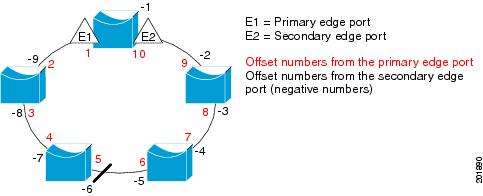
Note![]() You would never enter an offset value of 1 because that is the offset number of the primary edge port itself.
You would never enter an offset value of 1 because that is the offset number of the primary edge port itself.
If you have configured a preempt delay time by entering the rep preempt delay seconds interface configuration command and a link failure and recovery occurs, VLAN load balancing begins after the configured preemption time period elapses without another link failure. The alternate port specified in the load-balancing configuration blocks the configured VLANs and unblocks all other segment ports. If the primary edge port cannot determine the alternate port for VLAN balancing, the default action is no preemption.
Each port in a segment has a unique port ID. The port ID format is similar to the one used by the spanning tree algorithm: a port number (unique on the bridge) associated to a MAC address (unique in the network). To determine the port ID of a port, enter the show interface interface-id rep detail privileged EXEC command.
Examples
This example shows how to configure REP VLAN load balancing on the Switch B primary edge port (Gigabit Ethernet port 1) and to configure Gigabit Ethernet port 2 of Switch A as the alternate port to block VLANs 1 to 100. The alternate port is identified by its port ID, shown in bold in the output of the show interface rep detail command for the Switch A port.
This example shows how to configure VLAN load balancing by using a neighbor offset number and how to verify the configuration by entering the show interfaces rep detail privileged EXEC command:
Related Commands
|
|
|
|---|---|
Configures a waiting period after a segment port failure and recovery before REP VLAN load balancing is triggered. |
|
show interfaces rep detail |
Displays REP detailed configuration and status for all interfaces or the specified interface, including the administrative VLAN. |
rep lsl-age-timer
To configure the Link Status Layer (LSL) age timer for the time period that the REP interface remains up without receiving a hello from the REP neighbor, use the rep lsl-age-timer command in interface configuration mode on a Resilient Ethernet Protocol (REP) port. Use the no form of this command to return to the default time.
Syntax Description
The age-out time in milliseconds. The range is from 120 ms 10000 ms in 40-ms increments. The default is 5000 ms (5 seconds). |
Command Default
The REP link shuts down if it does not receive a hello message from a neighbor within 5000 ms.
Command Modes
Command History
|
|
|
|---|---|
Usage Guidelines
The LSL hello timer is set to the age-timer value divided by 3 so that there should be at least two LSL hellos sent during the LSL age-timer period. If no hellos are received within that time, the REP link shuts down.
In Cisco IOS Release 15.0(1)EY, the LSL age-timer range changed from 3000 to 10000 ms in 500-ms increments to 120 to 10000 ms in 40-ms increments. If the REP neighbor device is not running Cisco IOS Release 15.0(1)EY or later, you must use the shorter time range because the device does not accept values out of the earlier range.
EtherChannel port channel interfaces do not support LSL age timer values less than 1000 ms. Although you can configure the REP LSL age timer from 120 ms to 10000 ms, the port channel will remain up for at least 1000 ms (1 second), the mimimum LSL timeout value for port channels.
Examples
This example shows how to configure the REP LSL age timer on a REP link to 7000 ms:
You can verify the configured ageout time by entering the show interfaces rep detail privileged EXEC command.
Related Commands
|
|
|
|---|---|
show interfaces rep [ detail ] |
Displays REP configuration and status for all interfaces or the specified interface, including the configured LSL age-out timer value. |
rep preempt delay
To configure a waiting period after a segment port failure and recovery before Resilient Ethernet Protocol (REP) VLAN load balancing is triggered, use the rep preempt delay command in interface configuration mode on the REP primary edge port. Use the no form of this command to remove the configured delay.
Syntax Description
The number of seconds to delay REP preemption. The range is 15 to 300. |
Command Default
No preemption delay is set. If you do not enter the rep preempt delay command, the default is manual preemption with no delay.
Command Modes
Command History
|
|
|
|---|---|
Usage Guidelines
You must enter this command on the REP primary edge port.
You must enter this command and configure a preempt time delay if you want VLAN load balancing to automatically trigger after a link failure and recovery.
If VLAN load balancing is configured, after a segment port failure and recovery, the REP primary edge port starts a delay timer before VLAN load balancing occurs. Note that the timer restarts after each link failure. When the timer expires, the REP primary edge alerts the alternate port to perform VLAN load balancing (configured by using the rep block port interface configuration command) and prepares the segment for the new topology. The configured VLAN list is blocked at the alternate port, and all other VLANs are blocked at the primary edge port.
Examples
This example shows how to configure a REP preemption time delay of 100 seconds on the primary edge port:
Related Commands
|
|
|
|---|---|
Displays REP configuration and status for all interfaces or a specified interface. |
rep preempt segment
To manually start Resilient Ethernet Protocol (REP) VLAN load balancing on a segment, use the rep preempt segment command in privileged EXEC mode.
rep preempt segment segment_id
Syntax Description
Command Default
Command Modes
Command History
|
|
|
|---|---|
Usage Guidelines
When you enter the rep preempt segment segment-id command, a confirmation message appears before the command is executed because preemption can cause network disruption.
Enter this command on the switch on the segment that has the primary edge port.
If you do not configure VLAN load balancing, entering this command results in the default behavior—the primary edge port blocks all VLANs.
You configure VLAN load balancing by entering the rep block port { id port-id | neighbor_offset | preferred } vlan { vlan-list | all } interface configuration command on the REP primary edge port before you manually start preemption.
Examples
This example shows how to manually trigger REP preemption on segment 100 with the confirmation message:
Related Commands
|
|
|
|---|---|
show interfaces rep [ detail ] |
Displays REP configuration and status for all interfaces or the specified interface. |
rep segment
To enable Resilient Ethernet Protocol (REP) on the interface and to assign a segment ID to it, use the rep segment command in interface configuration mode. Use the no form of this command to disable REP on the interface.
rep segment segment-id [ edge [ no-neighbor ] [ primary ]] [ preferred ]
Syntax Description
Command Default
REP is disabled on the interface.
When REP is enabled on an interface, the default is for the port to be a regular segment port.
Command Modes
Command History
|
|
|
|---|---|
Usage Guidelines
REP ports must be Layer 2 trunk ports.
REP ports should not be configured as one of these port types:
You must configure two edge ports on each REP segment, a primary edge port and a port to act as a secondary edge port. If you configure two ports in a segment as the primary edge port, for example ports on different switches, the configuration is allowed, but the REP selects one of them to serve as the segment primary edge port.
–![]() There is no limit to the number of REP ports on a switch; however, only two ports on a switch can belong to the same REP segment.
There is no limit to the number of REP ports on a switch; however, only two ports on a switch can belong to the same REP segment.
–![]() If only one port on a switch is configured in a segment, the port should be an edge port.
If only one port on a switch is configured in a segment, the port should be an edge port.
–![]() If two ports on a switch belong to the same segment, they must be both edge ports, both regular segment ports, or one regular port and one edge no-neighbor port. An edge port and regular segment port on a switch cannot belong to the same segment.
If two ports on a switch belong to the same segment, they must be both edge ports, both regular segment ports, or one regular port and one edge no-neighbor port. An edge port and regular segment port on a switch cannot belong to the same segment.
–![]() If two ports on a switch belong to the same segment and one is configured as an edge port and one as a regular segment port (a misconfiguration), the edge port is treated as a regular segment port.
If two ports on a switch belong to the same segment and one is configured as an edge port and one as a regular segment port (a misconfiguration), the edge port is treated as a regular segment port.
If you configure two ports in a segment as the primary edge port, for example ports on different switches, the REP selects one of them to serve as the segment primary edge port. Enter the show rep topology privileged EXEC command on a port in the segment to verify which port is the segment primary edge port.
REP interfaces come up in a blocked state and remain in a blocked state until notified that it is safe to unblock. You need to be aware of this to avoid sudden connection losses.
You should configure REP only in networks with redundancy. Configuring REP in a network without redundancy causes loss of connectivity.
In networks where ports on a neighboring switch do not support REP, you can configure the non-REP facing ports as edge no-neighbor ports. These ports inherit all properties of edge ports and you can configure them as any other edge port, including to send STP or REP topology change notices to the aggregation switch. In this case, the STP topology change notice (TCN) that is sent is a multiple spanning-tree (MST) STP message.
Examples
This example shows how to enable REP on a regular (nonedge) segment port:
This example shows how to enable REP on a port and to identify the port as the REP primary edge port:
This example shows how to configure the same configuration when the interface has no external REP neighbor:
This example shows how to enable REP on a port and to identify the port as the REP secondary edge port:
You can verify your settings by entering the show interfaces rep privileged EXEC command. To verify which port in the segment is the primary edge port, enter the show rep topology privileged EXEC command.
Related Commands
|
|
|
|---|---|
show interfaces rep [ detail ] |
Displays REP configuration and status for all interfaces or the specified interface. |
show rep topology [ detail ] |
Displays information about all ports in the segment, including which one was configured and selected as the primary edge port. |
rep stcn
To configure the port to send REP segment topology change notifications (STCNs) to another interface, to other segments, or to Spanning Tree Protocol (STP) networks, use the rep stcn command in interface configuration mode on a Resilient Ethernet Protocol (REP) edge port. Use the no form of this command to disable the sending of STCNs to the interface, segment, or STP network.
rep stcn { interface interface-id | segment id-list | stp }
no rep stcn { interface | segment | stp }
Syntax Description
Command Default
Transmission of STCNs to other interfaces, segments, or STP networks is disabled.
Command Modes
Command History
|
|
|
|---|---|
Usage Guidelines
Enter this command on a segment edge port.
You use this command to notify other portions of the Layer 2 network of topology changes that occur in the local REP segment. This removes obsolete entries in the Layer 2 forwarding table in other parts of the network, which allows faster network convergence.
Examples
This example shows how to configure the REP primary edge port to send STCNs to segments 25 to 50:
You can verify your settings by entering the show interfaces rep detail privileged EXEC command.
Related Commands
|
|
|
|---|---|
show interfaces rep [ detail ] |
Displays REP configuration and status for all interfaces or the specified interface. |
reserved-only
To allocate only reserved addresses in the Dynamic Host Configuration Protocol (DHCP) address pool, use the reserved-only command in DHCP pool configuration mode. Use the no form of the command to return to the default.
Syntax Description
Command Default
Command Modes
Command History
|
|
|
|---|---|
Usage Guidelines
Entering the reserved-only command restricts assignments from the DHCP pool to preconfigured reservations. Unreserved addresses that are part of the network or on pool ranges are not offered to the client, and other clients are not served by the pool.
By entering this command, users can configure a group of switches with DHCP pools that share a common IP subnet and that ignore requests from clients of other switches.
To access DHCP pool configuration mode, enter the ip dhcp pool name global configuration command.
Examples
This example shows how to configure the DHCP pool to allocate only reserved addresses:
Related Commands
|
|
|
|---|---|
Displays the DHCP address pools. For syntax information, see the Cisco IOS Software Command Reference, Release 15.0. |
rmon collection stats
To collect Ethernet group statistics, which include usage statistics about broadcast and multicast packets, and error statistics about cyclic redundancy check (CRC) alignment errors and collisions use the rmon collection stats command in interface configuration mode. Use the no form of this command to return to the default setting.
rmon collection stats index [ owner name ]
no rmon collection stats index [ owner name ]
Syntax Description
Remote Network Monitoring (RMON) collection control index. The range is 1 to 65535. |
|
Command Default
Command Modes
Command History
|
|
|
|---|---|
Usage Guidelines
The RMON statistics collection command is based on hardware counters.
Examples
This example shows how to collect RMON statistics for the owner root:
You can verify your setting by entering the show rmon statistics privileged EXEC command.
Related Commands
|
|
|
|---|---|
Displays RMON statistics. For syntax information, see the Cisco IOS Software Command Reference, Release 15.0. |
sdm prefer
To configure the template used in Switch Database Management (SDM) resource allocation, use the sdm prefer command in global configuration mode. Use the no form of this command to return to the default template.
sdm prefer { default | dual-ipv4-and-ipv6 { default | routing } | qos | routing }
Syntax Description
Command Default
Command Modes
Command History
|
|
|
|---|---|
Usage Guidelines
You must reload the switch for the configuration to take effect.
If you enter the show sdm prefer command before you enter the reload privileged EXEC command, the show sdm prefer command shows the template currently in use and the template that will become active after a reload.
Use the no sdm prefer command to set the switch to the default template.
You must use a routing template on switches running the IP services image for Layer 3 functionality.
Do not use the routing template if you are not using Layer 3 functionality on your switch. Entering the sdm prefer routing global configuration command prevents other features from using the memory allocated to unicast routing in the routing template.
Do not use the ipv4 and ipv6 template if you do not plan to enable IPv6 functionality on the switch. Entering the sdm prefer ipv4-and-ipv6 global configuration command divides resources between IPv4 and IPv6, limiting those allocated to IPv4 forwarding.
Table 1-10 shows the resources allowed for each feature in the IPv4 templates and Table 1-11 shows the feature allocation in the dual-ipv4-and-ipv6 templates.
|
|
|
|
|
|---|---|---|---|
The first eight rows in the tables (unicast MAC addresses through security ACEs) represent approximate hardware boundaries set when a template is selected. If a section of a hardware resource is full, all processing overflow is sent to the CPU, seriously impacting switch performance. The last row is a guideline used to calculate hardware resource consumption related to the number of Layer 2 VLANs on the switch.
|
|
|
|
|---|---|---|
IPv6 policy-based routing ACEs2 |
||
|
1.Template estimates are based on a switch with 8 routed interfaces and approximately 1000 VLANs. |
Examples
This example shows how to use the QoS template:
This example shows how to configure the dual IPv4-and-IPv6 default template on a switch:
This example shows how to configure the IPv4-and-IPv6 routing template on a switch:
Related Commands
|
|
|
|---|---|
Displays the current SDM template in use or displays the templates that can be used, with approximate resource allocation per feature. |
service password-recovery
To enable the password-recovery mechanism (the default), use the service password-recovery command in global configuration mode. Use the no form of this command to disable part of the password-recovery functionality.
Syntax Description
Command Default
Command Modes
Command History
|
|
|
|---|---|
Usage Guidelines
This mechanism allows an end user with physical access to the switch to hold down the Express Setup button and interrupt the bootup process while the switch is powering up and to assign a new password.
When the password-recovery mechanism is disabled, interrupting the bootup process is allowed only if the user agrees to set the system back to the default configuration.
As a system administrator, you can use the no service password-recovery command to disable some of the functionality of the password recovery feature by allowing an end user to reset a password only by agreeing to return to the default configuration.
To use the password-recovery procedure, you must have physical access to the switch.
To delete the switch password and set a new one, follow these steps:
Step 1![]() Press the Express Setup button until the SETUP LED blinks green and the LED of an available switch downlink port blinks green.
Press the Express Setup button until the SETUP LED blinks green and the LED of an available switch downlink port blinks green.
If no switch downlink port is available for your PC or laptop connection, disconnect a device from one of the switch downlink ports. Press the Express Setup button again until the SETUP LED and the port LED blink green.
Step 2![]() Connect your PC or laptop to the port with the blinking green LED.
Connect your PC or laptop to the port with the blinking green LED.
The SETUP LED and the switch downlink port LED stop blinking and stay solid green.
Step 3![]() Press and hold the Express Setup button. Notice that the SETUP LED starts blinking green again. Continue holding the button until the SETUP LED turns solid green (approximately 5 seconds). Release the Express Setup button immediately.
Press and hold the Express Setup button. Notice that the SETUP LED starts blinking green again. Continue holding the button until the SETUP LED turns solid green (approximately 5 seconds). Release the Express Setup button immediately.
This procedure deletes the password without affecting any other configuration settings. You can now access the switch without a password through the console port or by using Device Manager.
Step 4![]() Enter a new password through Device Manager by using the Express Setup window or through the command line interface by using the enable secret global configuration command.
Enter a new password through Device Manager by using the Express Setup window or through the command line interface by using the enable secret global configuration command.
If you use the no service password-recovery command to control end user access to passwords, we recommend that you save a copy of the config file in a location away from the switch in case the end user uses the password recovery procedure and sets the system back to default values. Do not keep a backup copy of the config file on the switch.
If the switch is operating in VTP transparent mode, we recommend that you also save a copy of the vlan.dat file in a location away from the switch.
You can verify if password recovery is enabled or disabled by entering the show version privileged EXEC command.
Examples
This example shows how to disable password recovery on a switch so that a user can only reset a password by agreeing to return to the default configuration.
Related Commands
|
|
|
|---|---|
service-policy
To apply a policy map defined by the policy-map command to the input of a physical port or a switch virtual interface (SVI), use the service-policy command in interface configuration mode. Use the no form of this command to remove the policy map and port association.
service-policy input policy-map-name
no service-policy input policy-map-name
Syntax Description
Applies the specified policy map to the input of a physical port or an SVI. |
Note![]() Though visible in the command-line help strings, the history keyword is not supported, and you should ignore the statistics that it gathers. The output keyword is also not supported.
Though visible in the command-line help strings, the history keyword is not supported, and you should ignore the statistics that it gathers. The output keyword is also not supported.
Command Default
Command Modes
Command History
|
|
|
|---|---|
Usage Guidelines
Only one policy map per ingress port is supported.
Policy maps can be configured on physical ports or on SVIs. When VLAN-based quality of service (QoS) is disabled by using the no mls qos vlan-based interface configuration command on a physical port, you can configure a port-based policy map on the port. If VLAN-based QoS is enabled by using the mls qos vlan-based interface configuration command on a physical port, the switch removes the previously configured port-based policy map. After a hierarchical policy map is configured and applied on an SVI, the interface-level policy map takes effect on the interface.
You can apply a policy map to incoming traffic on a physical port or on an SVI. You can configure different interface-level policy maps for each class defined in the VLAN-level policy map. For more information about hierarchical policy maps, see the “Configuring QoS” chapter in the software configuration guide for this release.
Classification using a port trust state (for example, mls qos trust [ cos | dscp | ip-precedence ] and a policy map (for example, service-policy input policy-map-name) are mutually exclusive. The last one configured overwrites the previous configuration.
Examples
This example shows how to apply plcmap1 to an physical ingress port:
This example shows how to remove plcmap2 from a physical port:
This example shows how to apply plcmap1 to an ingress SVI when VLAN-based QoS is enabled:
This example shows how to create a hierarchical policy map and attach it to an SVI:
Related Commands
set
To classify IP traffic by setting a Differentiated Services Code Point (DSCP) or an IP-precedence value in the packet, use the set policy-map class command in configuration mode. Use the no form of this command to remove traffic classification.
set { dscp new-dscp | [ ip ] precedence new-precedence }
no set { dscp new-dscp | [ ip ] precedence new-precedence }
Syntax Description
Command Default
Command Modes
Policy-map class configuration
Command History
|
|
|
|---|---|
Usage Guidelines
If you have used the set ip dscp p olicy-map class configuration command, the switch changes this command to set dscp in the switch configuration. If you enter the set ip dscp policy-map class configuration command, this setting appears as set dscp in the switch configuration.
You can use the set ip precedence policy-map class configuration command or the set precedence policy-map class configuration command. This setting appears as set ip precedence in the switch configuration.
The set command is mutually exclusive with the trust policy-map class configuration command within the same policy map.
For the set dscp new-dscp or the set ip precedence new-precedence command, you can enter a mnemonic name for a commonly used value. For example, you can enter the set dscp af11 command, which is the same as entering the set dscp 10 command. You can enter the set ip precedence critical command, which is the same as entering the set ip precedence 5 command. For a list of supported mnemonics, enter the set dscp ? or the set ip precedence ? command to see the command-line help strings.
To return to policy-map configuration mode, use the exit command. To return to privileged EXEC mode, use the end command.
Examples
This example shows how to assign DSCP 10 to all FTP traffic without any policers:
You can verify your settings by entering the show policy-map privileged EXEC command.
Related Commands
setup
To configure the switch with its initial configuration, use the setup command in privileged EXEC mode.
Syntax Description
Defaults
Command Modes
Command History
|
|
|
|---|---|
Usage Guidelines
When you use the setup command, make sure that you have this information:
- IP address and network mask
- Password strategy for your environment
- Whether the switch will be used as the cluster command switch and the cluster name
When you enter the setup command, an interactive dialog, called the System Configuration Dialog, appears. It guides you through the configuration process and prompts you for information. The values shown in brackets next to each prompt are the default values last set by using either the setup command facility or the configure privileged EXEC command.
Help text is provided for each prompt. To access help text, press the question mark (?) key at a prompt.
To return to the privileged EXEC prompt without making changes and without running through the entire System Configuration Dialog, press Ctrl-C.
When you complete your changes, the setup program shows you the configuration command script that was created during the setup session. You can save the configuration in NVRAM or return to the setup program or the command-line prompt without saving it.
Examples
This is an example of output from the setup command:
Related Commands
|
|
|
|---|---|
Displays the running configuration on the switch. For syntax information, see the Cisco IOS Software Command Reference, Release 15.0. |
|
setup express
To enable Express Setup mode, use the setup express command in global configuration mode. Use the no form of this command to disable Express Setup mode.
Syntax Description
Command Default
Command Modes
Command History
|
|
|
|---|---|
Usage Guidelines
When Express Setup is enabled on a new (unconfigured) switch, pressing the Express Setup button for 2 seconds activates Express Setup. You can access the switch through an Ethernet port by using the IP address 10.0.0.1 and then can configure the switch with the web-based Express Setup program or the command-line interface (CLI)-based setup program.
When you press the Express Setup button for 2 seconds on a configured switch, the LEDs below the Express Setup button start blinking. If you press the Express Setup button for a total of 10 seconds, the switch configuration is deleted, and the switch reboots. The switch can then be configured like a new switch, either through the web-based Express Setup program or the CLI-based setup program.
Note![]() As soon as you make any change to the switch configuration (including entering no at the ning of the CLI-based setup program), configuration by Express Setup is no longer available. You can only run Express Setup again by pressing the Express Setup button for 10 seconds. This deletes the switch configuration and reboots the switch.
As soon as you make any change to the switch configuration (including entering no at the ning of the CLI-based setup program), configuration by Express Setup is no longer available. You can only run Express Setup again by pressing the Express Setup button for 10 seconds. This deletes the switch configuration and reboots the switch.
If Express Setup is active on the switch, entering the write memory or copy running-configuration startup-configuration privileged EXEC commands deactivates Express Setup. The IP address 10.0.0.1 is no longer valid on the switch, and your connection using this IP address ends.
The primary purpose of the no setup express command is to prevent someone from deleting the switch configuration by pressing the Mode button for 10 seconds.
Examples
This example shows how to enable Express Setup mode:
You can verify that Express Setup mode is enabled by pressing the Express Setup button:
- On an unconfigured switch, the LEDs below the Express Setup button turn solid green after 3 seconds.
- On a configured switch, the mode LEDs begin blinking after 2 seconds and turn solid green after 10 seconds.

This example shows how to disable Express Setup mode:
You can verify that Express Setup mode is disabled by pressing the Express Setup button. The LEDs do not turn solid green or begin blinking green if Express Setup mode is not enabled on the switch.
Related Commands
|
|
|
|---|---|
 Feedback