Table Of Contents
Catalyst 4900 Family Center Rack-Mount Kits Installation Note
Statement 1071—Warning Definition
Installing the WS-X4948-19CNTR= or the WS-X4948-23CNTR= Center Rack-Mount Kits
Center Rack-Mount Kit Contents
Installing the WS-X4948-19CNTR= or the WS-X4948-23CNTR=Center Rack-Mount Kit
Installing the WS-X4948E-19CNTR= or the WS-X4948E-23CNTR= Center Rack-Mount Kits
Center Rack-Mount Kit Contents
Installing the WS-X4948E-19CNTR= or the WS-X4948E-23CNTR=Center Rack-Mount Kit
Installing the WS-X4900M-23CNTR= Center Rack-Mount Kit
Center Rack-Mount Kit Contents
Installing the WS-X4900M-23CNTR=Center Rack-Mount Kit
Catalyst 4900 Family Center Rack-Mount Kits Installation Note
Revised: January 19, 2011This installation note contains instructions on how to install the Catalyst 4900 family of switch chassis in a telco-style rack using one of the five center rack-mount kits listed in Table 1.
Note Use these kits in place of the standard rack-mount brackets shipped with the chassis when center rack-mounting the switch in a telco-style rack.
For a complete description of switch hardware installation, safety, and maintenance procedures, refer to the appropriate hardware installation guide for your chassis. See the "Related Documentation" section.
Contents
This installation note is divided into the following topics:
•Installing the WS-X4948-19CNTR= or the WS-X4948-23CNTR= Center Rack-Mount Kits
•Installing the WS-X4948E-19CNTR= or the WS-X4948E-23CNTR= Center Rack-Mount Kits
•Installing the WS-X4900M-23CNTR= Center Rack-Mount Kit
Warnings
Throughout this publication, safety warnings appear in procedures that may harm you if performed incorrectly. A warning symbol precedes each warning statement.
Statement 1071—Warning Definition
Tools Required
You need the following tools to install the center rack-mount kits on the chassis and to mount the chassis in the equipment rack:
•No. 2 Phillips screwdriver
•No. 1 Phillips screwdriver
•Level
•Tape measure
Installing the WS-X4948-19CNTR= or the WS-X4948-23CNTR= Center Rack-Mount Kits
The WS-X4948-19CNTR= center rack-mount kit for 19-inch equipment racks and the WS-X4948-23CNTR= center rack-mount kit for 23-inch equipment racks can be installed only on the following four chassis:
•Catalyst 4948 switch
•Catalyst 4948-10GE switch
•Catalyst 4928-10GE switch
•Cisco ME 4924-10GE switch
Caution The center rack-mount brackets shipped in these two center rack-mount kits must be installed on the switch chassis in the forward direction only. If you install them backwards on the chassis, the airflow through the chassis is blocked, which will damage the switch.
Center Rack-Mount Kit Contents
Table 2 lists the contents of the two center rack-mount kits.
Installing the WS-X4948-19CNTR= or the WS-X4948-23CNTR=Center Rack-Mount Kit
To install either the 19-inch or the 23-inch center rack-mount kit on the appropriate switch, follow these steps:
Step 1 Place the switch chassis on an antistatic work surface.
Step 2 If the standard rack-mount brackets are attached to the chassis, you need to remove them by loosening and removing the eight M4 screws (four on each side) that secure the brackets to the chassis sides. (See Figure 1.) Set the screws and the brackets aside.
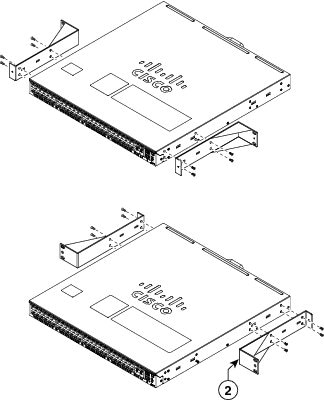
Figure 1 Removing the Standard Rack-Mount Brackets from the Chassis
Step 3 Verify that you have the correct center rack-mount kit for your chassis and for the equipment rack size (either 19-inch or 23-inch).
Step 4 Open your center rack-mount kit and inventory the contents. See Table 2 for the kit contents and quantities.
Step 5 Position the left-side bracket (stamped L) against the left side of the chassis with the bracket's four mounting holes aligned with the holes in the chassis as shown in Figure 2.
Step 6 Secure the bracket in place with four M4 mounting screws.
Step 7 Repeat step 5 and step 6 for the right-side bracket (stamped R).
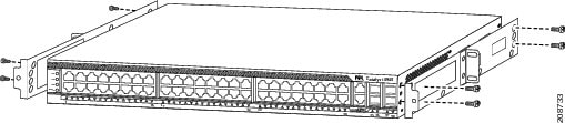
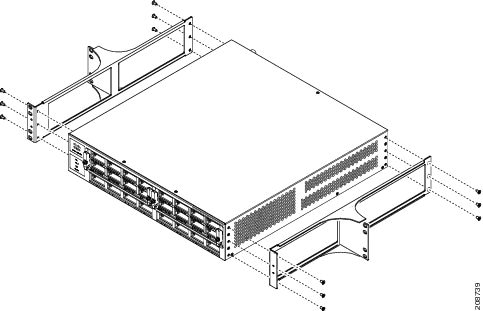
Figure 2 Installing the Center Rack-Mount Brackets on the Chassis
Step 8 Have one person carefully lift and position the chassis in the equipment rack so that the center rack-mount bracket ears are in contact with the rack posts. (See Figure 3.)
Note Use a tape measure or level to ensure that the chassis is positioned level in the equipment rack before you install the mounting screws.
Step 9 Adjust the chassis up or down in the rack until two screw holes in each center rack-mount bracket ear are aligned with mounting holes in the equipment rack post.
Step 10 While one person holds the chassis in place, secure the chassis to the equipment rack posts with either the four 10-32 x 3/4-inch or the four 12-24 x 3/4-inch Phillips-head machine screws (two on each side) that are supplied in the accessory kit.
Note If the equipment rack post-mounting holes are not threaded, you need to obtain the proper size cage-nuts to secure the center rack-mount mounting screws in place.
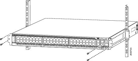
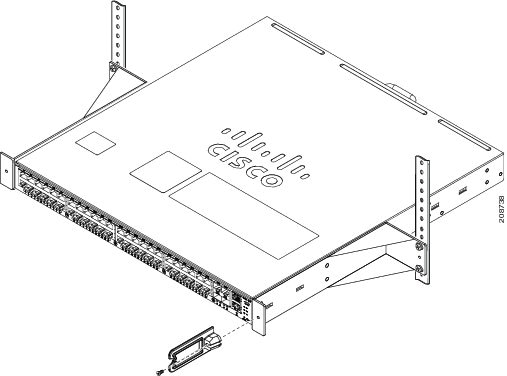
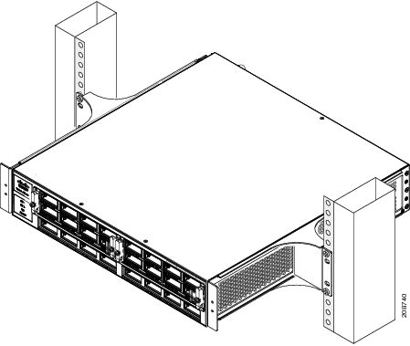
Figure 3 Attaching the Chassis to the Equipment Rack
Step 11 If you want to install the optional cable guide bracket, position the cable guide against either the left- or right-side threaded hole in the center rack-mount bracket as shown in Figure 4. Secure the cable guide bracket in place with one M4 screw.
Note For complete chassis installation procedures and additional product information, refer to the installation guide for your chassis.
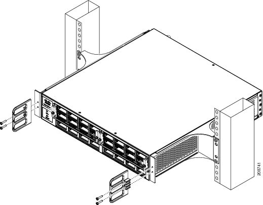
Figure 4 Attaching the Optional Cable Guide Bracket to the Center Rack-Mount Bracket
Installing the WS-X4948E-19CNTR= or the WS-X4948E-23CNTR= Center Rack-Mount Kits
The WS-X4948E-19CNTR= center rack-mount kit for 19-inch equipment racks and the WS-X4948E-23CNTR= center rack-mount kit for 23-inch equipment racks can be installed only on the Catalyst 4948E or the Catalyst 4948E-F switch chassis.
Note The Catalyst 4948E and the Catalyst 4948E-F differ in the direction of the airflow through the chassis. The Catalyst 4948E switch chassis has front to back airflow; the Catalyst 4948E-F switch chassis has back to front airflow.
Center Rack-Mount Kit Contents
Table 3 lists the contents of the two Catalyst 4948E and Catalyst 4948E-F center rack-mount kits.
Installing the WS-X4948E-19CNTR= or the WS-X4948E-23CNTR=Center Rack-Mount Kit
To install either the 19-inch or the 23-inch center rack-mount kit on the Catalyst 4948E or the Catalyst 4948E-F chassis, follow these steps:
Step 1 Place the switch chassis on an antistatic work surface.
Step 2 If the standard rack-mount brackets are attached to the chassis, you need to remove them by loosening and removing the eight M4 screws (four on each side) that secure the brackets to the chassis sides. (See Figure 5.) Set the screws and the brackets aside.
Note The standard rack-mount brackets can be installed either on the front of the chassis or the rear of the chassis. In either case, they must be removed before installing the center rack-mount brackets.
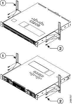
Figure 5 Removing the Standard Rack-Mount Brackets
Step 3 Verify that you have the correct center rack-mount kit for your chassis and for the equipment rack size.
Step 4 Open your center rack-mount kit and inventory the contents. See Table 3 for the kit contents and quantities.
Step 5 Determine how you want to position the chassis in the equipment rack. The center rack-mount brackets are reversible; they can be installed either on the front sides of the chassis or on the rear sides of the chassis.
Step 6 Position one of the brackets against the side of the chassis with the bracket's four mounting holes aligned with the holes in the chassis as shown in Figure 6.
Step 7 Secure the bracket in place with four M4 mounting screws.
Step 8 Repeat step 6 and step 7 for the second bracket.
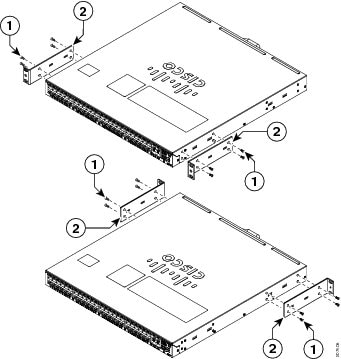
Figure 6 Installing the Center Rack-Mount Brackets on the Chassis
Step 9 Have one person carefully lift and position the chassis in the equipment rack so that the center rack-mount bracket ears are in contact with the rack posts.
Note Use a tape measure or level to ensure that the chassis is positioned level in the equipment rack before you install the mounting screws.
Step 10 Adjust the chassis up or down in the rack until two screw holes in each center rack-mount bracket ear are aligned with mounting holes in the equipment rack post.
Step 11 While one person holds the chassis in place, secure the chassis to the equipment rack posts with either the four 10-32 x 3/4-inch or the four 12-24 x 3/4-inch Phillips-head machine screws (two on each side). The screws are supplied in the accessory kit. (See Figure 7.)
Note If the equipment rack post-mounting holes are not threaded, you need to obtain the proper size cage-nuts to secure the center rack-mount mounting screws in place.
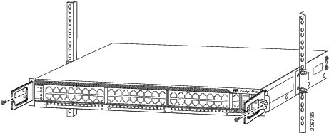
Figure 7 Mounting the Chassis in the Equipment Rack
Step 12 If you want to install the optional cable guide bracket, position the bracket against either the left- or right-side threaded hole in the center rack-mount bracket as shown in Figure 8. Secure the cable guide bracket in place with one M4 screw.
Note For complete chassis installation procedures and additional product information, refer to the installation guide for your chassis.
Figure 8 Installing the Optional Cable Guide to the Center Rack-Mount Bracket
Installing the WS-X4900M-23CNTR= Center Rack-Mount Kit
The WS-X4900M-23CNTR= center rack-mount kit for 23-inch equipment racks can be installed only on the Catalyst 4900M switch chassis.
Note The Catalyst 4900M center rack-mount brackets can be installed on the chassis in the forward direction only.
Center Rack-Mount Kit Contents
Table 4 lists the contents of the Catalyst 4900M center rack-mount kit.
Installing the WS-X4900M-23CNTR=Center Rack-Mount Kit
To install the 23-inch center rack-mount kit on the Catalyst 4900M chassis, perform the following steps:
Step 1 Place the switch chassis on an antistatic work surface.
Step 2 If necessary, remove the standard rack-mount brackets from the chassis by loosening and removing the 12 M4 screws (six on each side) that secure the brackets to the chassis sides. (See Figure 9.) Set the screws and the brackets aside.
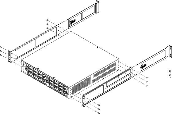
Figure 9 Removing the Standard Rack-Mount Brackets from the Catalyst 4900M Chassis
Step 3 Verify that you have the correct center rack-mount kit for your chassis.
Step 4 Open your center rack-mount kit and inventory the contents. See Table 4 for the kit contents and quantities.
Step 5 Position the left bracket (stamped L) against the left side of the chassis with the bracket's six mounting holes aligned with the mounting holes in the chassis as shown in Figure 10.
Step 6 Secure the bracket in place with six M4 mounting screws.
Step 7 Repeat step 5 and step 6 for the right-side bracket (stamped R).
Figure 10 Installing the Center Rack-Mount Brackets on the Chassis
Step 8 Have one person carefully lift and position the chassis in the equipment rack so that the center rack-mount bracket ears are in contact with the rack posts.
Note Use a tape measure or level to ensure that the chassis is installed level in the equipment rack.
Step 9 Adjust the chassis up or down in the rack until two screw holes in each center rack-mount bracket ear are aligned with mounting holes in the equipment rack post.
Step 10 While one person holds the chassis in place, secure the chassis to the equipment rack posts with either the four 10-32 x 3/4-inch or the four 12-24 x 3/4-inch Phillips-head machine screws (two on each side) that are supplied in the accessory kit. (See Figure 11.)
Note If the equipment rack post mounting holes are not threaded, you need to obtain the proper size cage-nuts to secure the center rack-mount mounting screws in place.
Figure 11 Mounting the Catalyst 4900M Chassis in the Equipment Rack
Step 11 If you want to install the optional cable guide bracket, position the cable guide against the two threaded holes in either the left- or right-side center rack-mount bracket as shown in Figure 12 and secure the cable guide bracket in place with two M4 screws provided with the cable guide bracket.
Note For complete chassis installation procedures and additional product information, refer to the installation guide for your chassis.
Figure 12 Installing the Optional Cable Guide to the Center Rack-Mount Bracket
Related Documentation
Table 5 lists the publications that contain the complete Catalyst 4900 switch chassis installation procedures.
Table 5 Catalyst 4900 Family Installation Guides
Chassis PublicationCatalyst 4948
Catalyst 4948
Catalyst 4948-10GE
Catalyst 4928-10GECisco ME 4924-10GE
Cisco ME 4924-10GE Ethernet Switch Hardware Installation Guide
Catalyst 4948E
Catalyst 4948E-FCatalyst 4948E and Catalyst 4948E-F Switch Installation Guide
Catalyst 4900M
This document is to be used in conjunction with the documents listed in the "Related Documentation" section.
Cisco and the Cisco Logo are trademarks of Cisco Systems, Inc. and/or its affiliates in the U.S. and other countries. A listing of Cisco's trademarks can be found at www.cisco.com/go/trademarks. Third party trademarks mentioned are the property of their respective owners. The use of the word partner does not imply a partnership relationship between Cisco and any other company. (1005R)
© 2011 Cisco Systems, Inc. All rights reserved.