Cisco Catalyst 4900M Switch Installation Guide
Bias-Free Language
The documentation set for this product strives to use bias-free language. For the purposes of this documentation set, bias-free is defined as language that does not imply discrimination based on age, disability, gender, racial identity, ethnic identity, sexual orientation, socioeconomic status, and intersectionality. Exceptions may be present in the documentation due to language that is hardcoded in the user interfaces of the product software, language used based on RFP documentation, or language that is used by a referenced third-party product. Learn more about how Cisco is using Inclusive Language.
- Updated:
- January 4, 2012
Chapter: Site Planning
Site Planning
This chapter describes how to prepare your site for installation of the Catalyst 4900M switch and contains these sections:
- Site Environmental Requirements
- Site Power Requirements
- Grounding Requirements
- Safety Overview
- Site Planning Checklist

Note![]() A site planning checklist is provided on page 2-8 to help ensure that you complete all site planning activities before you install the switch.
A site planning checklist is provided on page 2-8 to help ensure that you complete all site planning activities before you install the switch.
Site Environmental Requirements
Planning a proper location for the switch and layout for your equipment rack or wiring closet is essential for successful system operation. You should install the switch in an enclosed, secure area, ensuring that only qualified personnel have access to the switch and control of the environment. Equipment that is placed too closely together or that is inadequately ventilated can cause system overtemperature conditions. In addition, poor equipment placement can make chassis panels inaccessible and difficult to maintain.
The switch operates as a standalone system mounted in a rack in a secure wiring closet. It requires a dry, clean, well-ventilated, and air-conditioned environment. To ensure normal operation, maintain ambient airflow. If the airflow is blocked or restricted, or if the intake air is too warm, an overtemperature condition can occur. The switch environmental monitor can then shut down the system to protect the system components.
To ensure normal operation and avoid unnecessary maintenance, plan your site configuration and prepare your site before installation. After installation, make sure that the site maintains an ambient temperature of 0 to 40 ° C (32 to 104 ° F). It is essential to keep the area around the chassis as free from dust and foreign conductive material (such as metal flakes from nearby construction activity) as is possible.
Multiple switches can be rack-mounted with little or no clearance above and below the chassis. However, when mounting a switch in a rack with other equipment, or when placing it on the floor near other equipment, ensure that the exhaust from other equipment does not blow into the intake vents of the chassis.
Cooling air is drawn in through the right side and exhausted through the left side of the chassis. Keep the sides and rear clear of obstructions, including dust and foreign conductive material, and away from the exhaust ports of other equipment.
Appendix 1, “Specifications,” Specificationslists the operating and nonoperating environmental site requirements for the switches. To maintain normal operation and ensure high system availability, maintain an ambient temperature and EMI-free and continuous power at your site. The environmental ranges listed in are those within which the switch will continue to operate; however, a measurement that approaches the minimum or maximum of a range indicates a potential problem. You can maintain normal operation by anticipating and correcting environmental anomalies before they exceed the maximum operating range.
Site Power Requirements
This section describes the installation site power requirements for the Catalyst 4900M switch. Verify your site power before you install the switch.
This section consists of the following sections:
- Preinstallation Requirements
- Warnings and Cautions
- EMI Recommendations
- Power Requirements and Heat Dissipation
Preinstallation Requirements
Follow these requirements when preparing your site for the Catalyst 4900M switch installation:
- Connect each switch to separate wiring on a dedicated circuit; provide each switch with its own branch circuit connection with sufficient overcurrent protection and direct grounding to the branch circuit.
- To prevent a loss of input power, be sure the total maximum load on each AC circuit is within the current ratings of the wiring and breakers.
Warnings and Cautions
Follow these precautions when preparing your site for the Catalyst 4900M switch installation:


Warning![]() Read the installation instructions before connecting the system to the power source. Statement 1004
Read the installation instructions before connecting the system to the power source. Statement 1004
Warning![]() Installation of the equipment must comply with local and national electrical codes. Statement 1074
Installation of the equipment must comply with local and national electrical codes. Statement 1074
Warning![]() Ultimate disposal of this product should be handled according to all national laws and regulations. Statement 1040
Ultimate disposal of this product should be handled according to all national laws and regulations. Statement 1040
EMI Recommendations
Follow these guidelines when setting up the site wiring. When planning the location of the new system, consider electromagnetic interface (EMI), the distance limitations for signaling, and connector compatibility.
When wires are run for any significant distance in an electromagnetic field, radio frequency interference (RFI) can occur between the field and the signals on the wires.
- Bad plant wiring can result in radio frequency interference.
- Strong EMI, especially when caused by lightning or radio transmitters, can destroy the signal drivers and receivers in the switch and can create an electrical hazard by conducting power surges through lines and into equipment.
Note![]() To predict and remedy strong EMI, you might need to consult RFI experts.
To predict and remedy strong EMI, you might need to consult RFI experts.
Power Requirements and Heat Dissipation
The power requirements might be useful for planning the power distribution system needed to support the switches. Heat dissipation is an important consideration for sizing the air-conditioning requirements for an installation. Refer to Appendix 1, “Specifications,” for the power and heat ratings for a Catalyst 4900M switch.
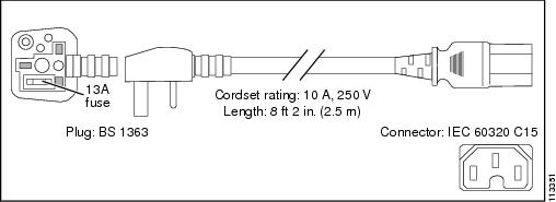
You will also need to provide power to the switch with the appropriate AC power cord for your location. Table 1-1 lists the specifications for the AC power cords that are available for the 1000 W AC-input power supply. The table includes references to illustrations of the AC power cords.
|
|
|
|
|
|
|---|---|---|---|---|
NEMA 5-151 |
||||
BS 13632 |
|
1.For Japan, ask your local electrical contractor to prepare the NEMA 5-20 power plug. |
Figure 1-1 CAB-IR2073-C15-AR=, CAB-7KACR= (Argentina)
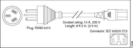
Figure 1-2 CAB-AS3112-C15-AU=, CAB-7KACA= (Australia and New Zealand)
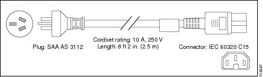
Figure 1-3 CAB-CEE77-C15-EU=, CAB-7KACE= (Continental Europe)
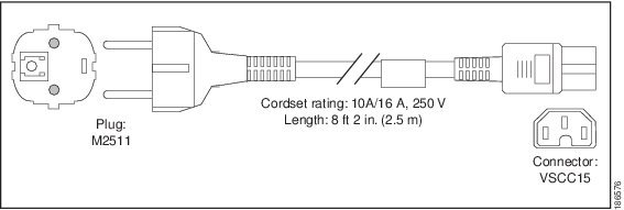
Figure 1-4 CAB-C2316-C15-IT=, CAB-7KACI= (Italy)
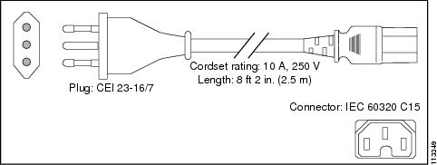
Figure 1-5 CAB-US515-C15-US=, CAB-7KAC= (North America)
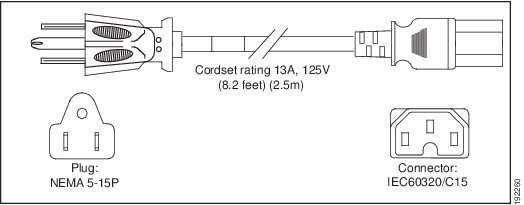
Figure 1-6 CAB-N5K6A-NA (North America)
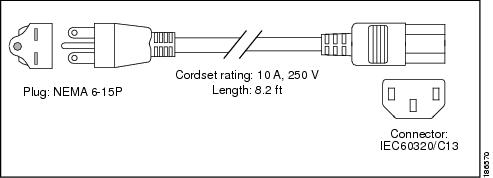
Figure 1-7 CAB-BS546-C15-SA (South Africa, India)
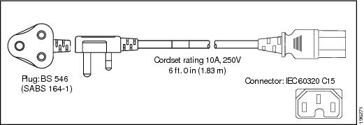
Figure 1-8 CAB-9K10A-SW=, CAB-7KACSW= (Switzerland)
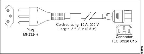
Figure 1-9 CAB-BS1363-C15-UK=, CAB-7KACU= (United Kingdom)
Grounding Requirements
Grounding is recommended on all AC-input or DC-input installations, using only approved copper connectors. Attach the provided two hole ground lug to the chassis using M4 x 8mm bolts and then to the central office (CO) or other interior ground system with number 6 AWG wire. The grounding pad is located on the rear of the chassis, as shown in Figure 1-10.
Figure 1-10 Grounding Pad Location
|
|
Safety Overview
This section provides safety information that you should read and understand to ensure a safe switch installation.
Ensuring Safety
Follow these guidelines to ensure your safety and protect the equipment. This list is not inclusive of all potentially hazardous situations that you may be exposed to as you install the switch, so be alert.
Warning![]() Only trained and qualified personnel should be allowed to install, replace, or service this equipment. Statement 1030
Only trained and qualified personnel should be allowed to install, replace, or service this equipment. Statement 1030
Warning![]() This equipment must be grounded. Never defeat the ground conductor or operate the equipment in the absence of a suitably installed ground conductor. Contact the appropriate electrical inspection authority or an electrician if you are uncertain that suitable grounding is available. Statement 1024
This equipment must be grounded. Never defeat the ground conductor or operate the equipment in the absence of a suitably installed ground conductor. Contact the appropriate electrical inspection authority or an electrician if you are uncertain that suitable grounding is available. Statement 1024
Note![]() To completely de-energize the system, unplug the power cord.
To completely de-energize the system, unplug the power cord.
- Always use caution when lifting heavy equipment.
- Always turn all power supplies off by unplugging all power cords before installing or removing a chassis.
- Keep the chassis area clear and free of dust during and after installation.
- Keep tools and chassis components off of the floor and away from foot traffic.
- Avoid wearing jewelry (including rings and chains) or other items that could get caught in the chassis. Avoid wearing any loose clothing, or securely fasten items such as ties, scarves, or sleeves.
- Install the system in compliance with the following local and national electrical codes.
Working Safely with Electricity
Follow these basic guidelines when working with any electrical equipment:
- Locate the emergency power-off switch for the room in which you are working before beginning installation.
- Disconnect all power and external cables before installing or removing a chassis.
- Do not work alone when potentially hazardous conditions exist.
- Never assume that power has been disconnected from a circuit; always check.
- Do not perform any action that creates a potential hazard to people or makes the equipment unsafe.
- Examine your work area carefully for possible hazards such as moist floors, ungrounded power extension cables, and missing safety grounds.
Preventing Electrostatic Discharge Damage
Electrostatic discharge (ESD) damage occurs when electronic cards or components are improperly handled and can result in complete or intermittent failures. Follow these guidelines to prevent ESD damage:
- Always use an ESD-preventive wrist or ankle strap, and ensure that it makes maximum contact with the skin.
- When coming into contact with any internal components, always use a wrist strap connected to one of the following:
–![]() Any unpainted grounded surface on the chassis or equipment rack
Any unpainted grounded surface on the chassis or equipment rack
Site Planning Checklist
Table 1-2 lists the site planning activities that you should perform before you install the Catalyst 4900M switch. Completing each activity helps to ensure a successful switch installation.
 Feedback