Release Notes for the Catalyst 3750, 3560, 2970, and 2960 Switches, Cisco IOS Release 12.2(40)SE
Available Languages
Table of Contents
Release Notes for the Catalyst 3750, 3560, 2970, and 2960 Switches, Cisco IOS Release 12.2(40)SE
Device Manager System Requirements
Finding the Software Version and Feature Set
Catalyst 3750G Integrated Wireless LAN Controller Switch Software Compatibility
Upgrading a Switch by Using the Device Manager or Network Assistant
Upgrading a Switch by Using the CLI
Recovering from a Software Failure
Catalyst 3750, 3560, and 2960 switches
Catalyst 3750 and 3560 Switches
Minimum Cisco IOS Release for Major Features
Stacking (Catalyst 3750 or Cisco EtherSwitch service module switch stack only)
Updates to the Catalyst 3750 and 3560 Switch Software Configuration Guides
Configuring Source-Specific Multicast
Configuring Embedded Event Manager (New Chapter)
Configuring Embedded Event Manager
Displaying Embedded Event Manager Information
Unsupported Embedded Event Manager Commands
Updates to the Catalyst 2960 Switch Software Configuration Guide
Updates to the Catalyst 3750 Switch Command Reference Guide
Updates to the Catalyst 2960 Switch Command Reference Guide
Updates to the System Message Guides
Updates to the Catalyst 3750, 3560, 2970, and 2960 Hardware Installation Guide
Updates to the Catalyst 3750 Getting Started Guide
Update to the Catalyst 3750 Switch Regulatory Compliance and Safety Information
Statement 370—Attaching the Cisco RPS to the RPS Receptacle
Obtaining Documentation, Obtaining Support, and Security Guidelines
Release Notes for the Catalyst 3750, 3560, 2970, and 2960 Switches, Cisco IOS Release 12.2(40)SE
Cisco IOS Release 12.2(40)SE runs on all Catalyst 3750, 3560, 2970, and 2960 switches and on Cisco EtherSwitch service modules.
The Catalyst 3750 switches and the Cisco EtherSwitch service modules support stacking through Cisco StackWise technology. The Catalyst 3560, 2970, and 2960 switches do not support switch stacking. Unless otherwise noted, the term switch refers to a standalone switch and to a switch stack.
These release notes include important information about Cisco IOS Release 12.2(40)SE and later and any limitations, restrictions, and caveats that apply to the releases. Verify that these release notes are correct for your switch:
- If you are installing a new switch, see the Cisco IOS release label on the rear panel of your switch.
- If your switch is on, use the show version privileged EXEC command. See the “Finding the Software Version and Feature Set” section.
- If you are upgrading to a new release, see the software upgrade filename for the software version. See the “Deciding Which Files to Use” section.
For the complete list of Catalyst 3750, 3560, 2970, and 2960 switch documentation and of Cisco EtherSwitch service module documentation, see the “Related Documentation” section.
You can download the switch software from this site (registered Cisco.com users with a login password):
http://www.cisco.com/kobayashi/sw-center/sw-lan.shtml
This software release is part of a special release of Cisco IOS software that is not released on the same 8-week maintenance cycle that is used for other platforms. As maintenance releases and future software releases become available, they will be posted to Cisco.com in the Cisco IOS software area.
Contents
This information is in the release notes:
- “System Requirements” section
- “Upgrading the Switch Software” section
- “Installation Notes” section
- “New Features” section
- “Minimum Cisco IOS Release for Major Features” section
- “Limitations and Restrictions” section
- “Important Notes” section
- “Open Caveats” section
- “Resolved Caveats” section
- “Documentation Updates” section
- “Obtaining Documentation, Obtaining Support, and Security Guidelines” section
System Requirements
The system requirements are described in these sections:
- “Hardware Supported” section
- “Device Manager System Requirements” section
- “Cluster Compatibility” section
- “CNA Compatibility” section
Hardware Supported
Table 1 lists the hardware supported on this release.
24 10/100/1000 PoE1 ports, 2 SFP2 module slots, and an integrated wireless LAN controller supporting up to 25 access points. |
Cisco IOS Release 12.2(25)FZ or Cisco IOS Release 12.2(35)SE |
|
24 10/100/1000 PoE ports, 2 SFP module slots, and an integrated wireless LAN controller supporting up to 50 access points |
Cisco IOS Release 12.2(25)FZ or Cisco IOS Release 12.2(35)SE |
|
16 10/100/1000 Ethernet ports and 1 XENPAK 10-Gigabit Ethernet module slot |
||
8 10/100 PoE ports and 1 dual-purpose port3 (one 10/100/1000BASE-T copper port and one SFP module slot) |
||
8 10/100 Ethernet ports and 1 dual-purpose port (one 10/100/1000BASE-T copper port and one SFP module slot) |
||
7 10/100/1000 Ethernet ports and 1 dual-purpose port (one 10/100/1000BASE-T copper port and one SFP module slot) |
||
24 10/100BASE-T Ethernet ports and 2 dual-purpose ports (two 10/100/1000BASE-T copper ports and two SFP module slots) |
||
48 10/100BASE-T Ethernet ports and 2 dual-purpose ports (two 10/100/1000BASE-T copper ports and two SFP module slots) |
||
24 10/100BASE-T Ethernet ports and 2 10/100/1000BASE-T Ethernet ports |
||
48 10/100BASE-T Ethernet ports 2 10/100/1000BASE-T Ethernet ports |
||
24 10/100/1000BASE-T Ethernet ports, including 4 dual-purpose ports (four 10/100/1000BASE-T copper ports and four SFP module slots) |
||
48 10/100/1000BASE-T Ethernet ports, including 4 dual-purpose ports (four 10/100/1000BASE-T copper ports and four SFP module slots) |
||
NME-16ES-1G4 |
16 10/100 ports, 1 10/100/1000 Ethernet port, no StackWise connector ports, single-wide |
|
16 10/100 PoE ports, 1 10/100/1000 Ethernet port, no StackWise connector ports, single-wide |
||
23 10/100 ports, 1 10/100/1000 PoE port, no StackWise connector ports, extended single-wide |
||
23 10/100 PoE ports, 1 10/100/1000 PoE port, no StackWise connector ports, extended single-wide |
||
24 10/100 PoE ports, 1 SFP module port, 2 StackWise connector ports, extended double-wide |
||
48 10/100 PoE ports, 2 SFP module ports, no StackWise connector ports, extended double-wide |
||
1000BASE-CWDM5, -LX, SX, -T, -ZX 100BASE-FX MMF6 |
||
XENPAK modules7 |
||
Cisco RPS 675 Redundant Power System Cisco RPS 300 Redundant Power System (supported only on the Catalyst 2960 switch) |
Supported on all software releases Supported on all software releases |
Device Manager System Requirements
These sections describes the hardware and software requirements for using the device manager:
Hardware Requirements
Table 2 lists the minimum hardware requirements for running the device manager.
Software Requirements
Table 3 lists the supported operating systems and browsers for using the device manager. The device manager verifies the browser version when starting a session to ensure that the browser is supported.

Note![]() The device manager does not require a plug-in.
The device manager does not require a plug-in.
|
Microsoft Internet Explorer
10
|
|||
|---|---|---|---|
Cluster Compatibility
You cannot create and manage switch clusters through the device manager. To create and manage switch clusters, use the command-line interface (CLI) or the Network Assistant application.
When creating a switch cluster or adding a switch to a cluster, follow these guidelines:
- When you create a switch cluster, we recommend configuring the highest-end switch in your cluster as the command switch.
- If you are managing the cluster through Network Assistant, the switch with the latest software should be the command switch.
- The standby command switch must be the same type as the command switch. For example, if the command switch is a Catalyst 3750 switch, all standby command switches must be Catalyst 3750 switches.
For additional information about clustering, see Getting Started with Cisco Network Assistant and Release Notes for Cisco Network Assistant (not orderable but available on Cisco.com), the software configuration guide, the command reference, and the Cisco EtherSwitch service module feature guide.
CNA Compatibility
Cisco IOS 12.2(40)SE is only compatible with Cisco Network Assistant (CNA) 5.0 and later. You can download Cisco Network Assistant from this URL:
http://www.cisco.com/pcgi-bin/tablebuild.pl/NetworkAssistant
For more information about Cisco Network Assistant, see the Release Notes for Cisco Network Assistant on Cisco.com.
Upgrading the Switch Software
These are the procedures for downloading software. Before downloading software, read this section for important information:
- “Finding the Software Version and Feature Set” section
- “Deciding Which Files to Use” section
- “Catalyst 3750G Integrated Wireless LAN Controller Switch Software Compatibility” section
- “Archiving Software Images” section
- “Upgrading a Switch by Using the Device Manager or Network Assistant” section
- “Upgrading a Switch by Using the CLI” section
- “Recovering from a Software Failure” section
Finding the Software Version and Feature Set
The Cisco IOS image is stored as a bin file in a directory that is named with the Cisco IOS release. A subdirectory contains the files needed for web management. The image is stored on the system board flash device (flash:).
You can use the show version privileged EXEC command to see the software version that is running on your switch. The second line of the display shows the version.
Note![]() For Catalyst 3750 and 3560 switches and the Cisco EtherSwitch service modules, although the show version output always shows the software image running on the switch, the model name shown at the end of this display is the factory configuration (IP base image [formerly known as the SMI] or IP services image [formerly known as the EMI]) and does not change if you upgrade the software image.
For Catalyst 3750 and 3560 switches and the Cisco EtherSwitch service modules, although the show version output always shows the software image running on the switch, the model name shown at the end of this display is the factory configuration (IP base image [formerly known as the SMI] or IP services image [formerly known as the EMI]) and does not change if you upgrade the software image.
You can also use the dir filesystem : privileged EXEC command to see the directory names of other software images that you might have stored in flash memory.
Deciding Which Files to Use
The upgrade procedures in these release notes describe how to perform the upgrade by using a combined tar file. This file contains the Cisco IOS image file and the files needed for the embedded device manager. You must use the combined tar file to upgrade the switch through the device manager. To upgrade the switch through the command-line interface (CLI), use the tar file and the archive download-sw privileged EXEC command.
For the Catalyst 3750 and 3560 switches, Cisco IOS Release 12.2(25)SEA and earlier referred to the image that provides Layer 2+ features and basic Layer 3 routing as the standard multilayer image (SMI). The image that provides full Layer 3 routing and advanced services was referred to as the enhanced multilayer image (EMI).
Cisco IOS Release 12.2(25)SEB and later refers to the SMI as the IP base image and the EMI as the IP services image.
Cisco IOS Release 12.2(25)SEB and later refers to the Catalyst 2970 image as the LAN base image.
Table 4 lists the different file-naming conventions before and after Cisco IOS Release 12.2(25)SEB.
Table 5 lists the filenames for this software release.
Note![]() For IPv6 capability on the Catalyst 3750 or 3560 switch or on the Cisco EtherSwitch service modules, you must order the advanced IP services image upgrade from Cisco.
For IPv6 capability on the Catalyst 3750 or 3560 switch or on the Cisco EtherSwitch service modules, you must order the advanced IP services image upgrade from Cisco.
Catalyst 3750 IP base image and device manager files. |
|
Catalyst 3750 IP services image and device manager files. |
|
Catalyst 3750 IP base cryptographic image and device manager files. |
|
Catalyst 3750 IP services cryptographic image and device manager files. |
|
Catalyst 3750 advanced IP services image, cryptographic file, and device manager files. |
|
Catalyst 3560 IP base image file and device manager files. |
|
Catalyst 3560 IP services image and device manager files. |
|
Catalyst 3560 IP base cryptographic image and device manager files. |
|
Catalyst 3560 IP services cryptographic image and device manager files. This image has the Kerberos, SSH, Layer 2+, and full Layer 3 features. |
|
Catalyst 3560 advanced IP services image, cryptographic file, and device manager files. |
|
Catalyst 2970 image file and device manager files. |
|
Catalyst 2970 cryptographic image file and device manager files. |
|
Catalyst 2960 image file and device manager files. |
|
Catalyst 2960 cryptographic image file and device manager files. This image has the Kerberos and SSH features. |
Catalyst 3750G Integrated Wireless LAN Controller Switch Software Compatibility
The Catalyst 3750 Integrated Wireless LAN Controller Switch is an integrated Catalyst 3750 switch and Cisco 4400 series wireless LAN controller that supports up to 25 or 50 lightweight access points. The switch and the internal controller run separate software versions, which must be upgraded separately. If the image versions are not compatible, the wireless LAN controller switch could stop functioning. Table 6 is the compatibility matrix for Catalyst 3750 and wireless controller.
For information about this controller software release, see the Release Notes for Cisco Wireless LAN Controllers and Lightweight Access Point, Release 4.0.x.0. For controller software upgrade procedure, see the Cisco Wireless LAN Controller Configuration Guide Release 4.0.
Archiving Software Images
Before upgrading your switch software, make sure that you have archived copies of the current Cisco IOS release and the Cisco IOS release to which you are upgrading. You should keep these archived images until you have upgraded all devices in the network to the new Cisco IOS image and until you have verified that the new Cisco IOS image works properly in your network.
Cisco routinely removes old Cisco IOS versions from Cisco.com. See Product Bulletin 2863 for more information:
http://www.cisco.com/en/US/products/sw/iosswrel/ps5187/prod_bulletin0900aecd80281c0e.html
You can copy the bin software image file on the flash memory to the appropriate TFTP directory on a host by using the copy flash: tftp: privileged EXEC command.
Note![]() Although you can copy any file on the flash memory to the TFTP server, it is time consuming to copy all of the HTML files in the tar file. We recommend that you download the tar file from Cisco.com and archive it on an internal host in your network.
Although you can copy any file on the flash memory to the TFTP server, it is time consuming to copy all of the HTML files in the tar file. We recommend that you download the tar file from Cisco.com and archive it on an internal host in your network.
You can also configure the switch as a TFTP server to copy files from one switch to another without using an external TFTP server by using the tftp-server global configuration command. For more information about the tftp-server command, see the “Basic File Transfer Services Commands” section of the Cisco IOS Configuration Fundamentals Command Reference, Release 12.2 at this URL:
http://www.cisco.com/en/US/products/sw/iosswrel/ps1835/products_command_reference_chapter09186a00800ca744.html
Upgrading a Switch by Using the Device Manager or Network Assistant
You can upgrade switch software by using the device manager or Network Assistant. For detailed instructions, click Help.
Note![]() When using the device manager to upgrade your switch, do not use or close your browser session after the upgrade process begins. Wait until after the upgrade process completes.
When using the device manager to upgrade your switch, do not use or close your browser session after the upgrade process begins. Wait until after the upgrade process completes.
Upgrading a Switch by Using the CLI
This procedure is for copying the combined tar file to the switch. You copy the file to the switch from a TFTP server and extract the files. You can download an image file and replace or keep the current image.
To download software, follow these steps:
Step 1![]() Use Table 5 to identify the file that you want to download.
Use Table 5 to identify the file that you want to download.
Step 2![]() Download the software image file. If you have a SmartNet support contract, go to this URL, and log in to download the appropriate files:
Download the software image file. If you have a SmartNet support contract, go to this URL, and log in to download the appropriate files:
http://www.cisco.com/kobayashi/sw-center/sw-lan.shtml
To download the image for a Catalyst 2960 switch, click Catalyst 2960 software. To obtain authorization and to download the cryptographic software files, click Catalyst 2960 3DES Cryptographic Software.
To download the image for a Catalyst 2970 switch, click Catalyst 2970 software. To obtain authorization and to download the cryptographic software files, click Catalyst 2970 3DES Cryptographic Software.
To download the IP services image (formerly known as the EMI) or IP base image (formerly known as the SMI) files for a Catalyst 3560 switch, click Catalyst 3560 software. To obtain authorization and to download the cryptographic software files, click Catalyst 3560 3DES Cryptographic Software.
To download the IP services image (formerly known as the EMI) or IP base image (formerly known as the SMI) files for a Catalyst 3750 switch, click Catalyst 3750 software. To obtain authorization and to download the cryptographic software files, click Catalyst 3750 3DES Cryptographic Software.

Step 3![]() Copy the image to the appropriate TFTP directory on the workstation, and make sure that the TFTP server is properly configured.
Copy the image to the appropriate TFTP directory on the workstation, and make sure that the TFTP server is properly configured.
For more information, see Appendix B in the software configuration guide for this release.
Step 4![]() Log into the switch through the console port or a Telnet session.
Log into the switch through the console port or a Telnet session.
Step 5![]() (Optional) Ensure that you have IP connectivity to the TFTP server by entering this privileged EXEC command:
(Optional) Ensure that you have IP connectivity to the TFTP server by entering this privileged EXEC command:
For more information about assigning an IP address and default gateway to the switch, see the software configuration guide for this release.
Step 6![]() Download the image file from the TFTP server to the switch. If you are installing the same version of software that is currently on the switch, overwrite the current image by entering this privileged EXEC command:
Download the image file from the TFTP server to the switch. If you are installing the same version of software that is currently on the switch, overwrite the current image by entering this privileged EXEC command:
The /overwrite option overwrites the software image in flash memory with the downloaded one.
The /reload option reloads the system after downloading the image unless the configuration has been changed and not saved.
For // location, specify the IP address of the TFTP server.
For / directory / image-name .tar, specify the directory (optional) and the image to download. Directory and image names are case sensitive.
This example shows how to download an image from a TFTP server at 198.30.20.19 and to overwrite the image on the switch:
You can also download the image file from the TFTP server to the switch and keep the current image by replacing the /overwrite option with the /leave-old-sw option.
Installation Notes
You can assign IP information to your switch by using these methods:
- The Express Setup program, as described in the switch getting started guide.
- The CLI-based setup program, as described in the switch hardware installation guide.
- The DHCP-based autoconfiguration, as described in the switch software configuration guide.
- Manually assigning an IP address, as described in the switch software configuration guide.
Note![]() If you are upgrading a Catalyst 3750 or a 2950 switch running Cisco IOS Release 12.1(11)AX, which uses the IEEE 802.1x feature, you must re-enable IEEE 802.1x after upgrading the software. For more information, see the “Cisco IOS Notes” section.
If you are upgrading a Catalyst 3750 or a 2950 switch running Cisco IOS Release 12.1(11)AX, which uses the IEEE 802.1x feature, you must re-enable IEEE 802.1x after upgrading the software. For more information, see the “Cisco IOS Notes” section.
Note![]() When upgrading or downgrading from Cisco IOS Release 12.2(18)SE, you might need to reconfigure the switch with the same password that you were using when running Cisco IOS Release 12.2(18)SE. This problem only occurs when changing from Cisco IOS Release 12.2(18)SE to any other release. (CSCed88768)
When upgrading or downgrading from Cisco IOS Release 12.2(18)SE, you might need to reconfigure the switch with the same password that you were using when running Cisco IOS Release 12.2(18)SE. This problem only occurs when changing from Cisco IOS Release 12.2(18)SE to any other release. (CSCed88768)
New Features
These sections describe the new supported hardware and the new and updated software features provided in this release:
New Hardware Features
There are no new hardware features for this release. For a list of all supported hardware, see the “Hardware Supported” section.
Catalyst 3750, 3560, and 2960 switches
These are the new features for the Catalyst 3750, 3560, 2970, and 2960 switches:
- Configuration replacement and rollback to replace the running configuration on a switch with any saved Cisco IOS configuration file
- Support for the Link Layer Discovery Protocol Media Extensions (LLDP-MED) location TLV that provides location information from the switch to the endpoint device
- Support for the Cisco MAC Notification MIB.
Catalyst 3750 and 3560 Switches
These are the new features for the Catalyst 3750 and 3560 switches.
- Automatic quality of service (QoS) Voice over IP (VoIP) enhancement for port -based trust of DSCP and priority queuing for egress traffic
- Dynamic voice virtual LAN (VLAN) for multidomain authentication (MDA) to allow a dynamic voice VLAN on an MDA-enabled port
- Embedded event manager (EEM) for device and system management to monitor key system events and then act on them though a policy (IP services image only)
- Internet Group Management Protocol (IGMP) Helper to allow the switch to forward a hosts request to join a multicast stream to a specific IP destination address
- IP Service Level Agreements (IP SLAs) support to measure network performance by using active traffic monitoring
- IP SLAs EOT to use the output from IP SLAs tracking operations triggered by an action such as latency, jitter, or packet loss for a standby router failover takeover
- Multicast virtual routing and forwarding (VRF) Lite for configuring multiple private routing domains for network virtualization and virtual private multicast networks
- Support for Enhanced Interior Gateway Routing Protocol (EIGRP) IPv6, an enhanced version of IGRP. It utilizes IPv6 transport, communicates with IPv6 peers, and advertises IPv6 routes
- Support for the SSM PIM protocol to optimize multicast applications, such as video
- Support for these IP services, making them VRF aware so that they can operate on multiple routing instances: HSRP, uRPF, ARP, SNMP, IP SLA, TFTP, FTP, syslog, traceroute, and ping
Catalyst 2960 switches only
- IP Service Level Agreements (IP SLAs) responder support that allows the switch to be a target device for IP SLAs active traffic monitoring (Catalyst 2960 switches)
- IPv6 host support for basic IPv6 management of the Catalyst 2960 switch (Catalyst 2960 switches)
- Multicast Listener Discovery (MLD) snooping to enable distribution of IP version 6 (IPv6) multicast data to clients and routers in a switched network (Catalyst 2960 switches)
Minimum Cisco IOS Release for Major Features
Table 7 lists the minimum software release required to support the major features of the Catalyst 3750, 3560, 2970, and 2960 switches and the Cisco EtherSwitch service modules.
Embedded event manager (EEM) for device and system management (IP services image only) |
||
Support for Enhanced Interior Gateway Routing Protocol (EIGRP) IPv6 |
||
Dynamic voice virtual LAN (VLAN) for multidomain authentication (MDA)-enabled ports |
||
VRF-aware support for these IP services: HSRP, uRPF, ARP, SNMP, IP SLA, TFTP, FTP, syslog, traceroute, and ping |
||
Link Layer Discovery Protocol (LLDP) and LLDP Media Endpoint Discovery (LLDP-MED) |
||
Generic online diagnostics to test the hardware functionality of the supervisor engine |
||
Stack MAC persistent timer and archive download enhancements |
||
OSPF and EIGRP Nonstop forwarding capability (IP services image only) |
||
IPv6 router ACLs for inbound Layer 3 management traffic in the IP base and IP services image |
||
Generic online diagnostics to test the hardware functionality of the supervisor engine |
||
Multiple spanning-tree (MST) based on the IEEE 802.1s standard |
||
Support for configuring private-VLAN ports on interfaces that are configured for dynamic ARP inspection (IP base image [formerly known as the SMI] only) |
||
Support for IP source guard on private VLANs (IP base image [formerly known as the SMI] only) |
||
Support for VLAN-based QoS14 and hierarchical policy maps on SVIs15 |
||
Layer 2 point-to-point tunneling and Layer 2 point-to-point tunneling bypass |
||
Support for SSL version 3.0 for secure HTTP communication (cryptographic images only) |
||
Support for configuring private-VLAN ports on interfaces that are configured for dynamic ARP inspection (IP services image [formerly known as the EMI] only) |
||
Support for IP source guard on private VLANs (IP services image [formerly known as the EMI] only) |
||
Cisco intelligent power management to limit the power allowed on a port, or pre-allocate (reserve) power for a port. |
||
IEEE 802.1x accounting and MIBs (IEEE 8021-PAE-MIB and CISCO-PAE-MIB) |
||
Private VLAN (IP services image [formerly known as the EMI] only) |
||
Limitations and Restrictions
You should review this section before you begin working with the switch. These are known limitations that will not be fixed, and there is not always a workaround. Some features might not work as documented, and some features could be affected by recent changes to the switch hardware or software.
This section contains these limitations:
Cisco IOS Limitations
Unless otherwise noted, these limitations apply to the Catalyst 3750, 3560, 2970, and 2960 switches and the Cisco EtherSwitch service modules:
- “Configuration” section
- “Ethernet” section
- “Fallback Bridging” section
- “HSRP” section
- “IP” section
- “IP Telephony” section
- “MAC Addressing” section
- “MAC Addressing” section
- “Multicasting” section
- “Power” section
- “QoS” section
- “Routing” section
- “SPAN and RSPAN” section
- “Stacking (Catalyst 3750 or Cisco EtherSwitch service module switch stack only)” section
- “Trunking” section
- “VLAN” section
Configuration
These are the configuration limitations:
This problem occurs under these conditions:
–![]() When the switch is booted up without a configuration (no config.text file in flash memory).
When the switch is booted up without a configuration (no config.text file in flash memory).
–![]() When the switch is connected to a DHCP server that is configured to give an address to it (the dynamic IP address is assigned to VLAN 1).
When the switch is connected to a DHCP server that is configured to give an address to it (the dynamic IP address is assigned to VLAN 1).
–![]() When an IP address is configured on VLAN 1 before the dynamic address lease assigned to VLAN 1 expires.
When an IP address is configured on VLAN 1 before the dynamic address lease assigned to VLAN 1 expires.
The workaround is to reconfigure the static IP address. (CSCea71176 and CSCdz11708)
- (Catalyst 3750 or 3560 switches and Cisco EtherSwitch service modules) When the show interface privileged EXEC is entered on a port that is running IEEE 802.1Q, inconsistent statistics from ports running IEEE 802.1Q might be reported. The workaround is to upgrade to Cisco IOS Release 12.1(20)EA1. (CSCec35100)
- (Catalyst 3750 or 3560 switches and Cisco EtherSwitch service modules) When you change a port from a nonrouted port to a routed port or the reverse, the applied auto-QoS setting is not changed or updated when you verify it by using the show running interface or show mls qos interface user EXEC commands. These are the workarounds:
1. Disable auto-QoS on the interface.
2. Change the routed port to a nonrouted port or the reverse.
3. Re-enable auto-QoS on the interface. (CSCec44169)
- The DHCP snooping binding database is not written to flash memory or a remote file in any of these situations:
–![]() (Catalyst 3750 switch and Cisco EtherSwitch service modules) When the Network Time Protocol (NTP) is configured, but the NTP clock is not synchronized. You can check the clock status by entering the show NTP status privileged EXEC command and verifying that the network connection to the NTP server and the peer work correctly.
(Catalyst 3750 switch and Cisco EtherSwitch service modules) When the Network Time Protocol (NTP) is configured, but the NTP clock is not synchronized. You can check the clock status by entering the show NTP status privileged EXEC command and verifying that the network connection to the NTP server and the peer work correctly.
–![]() (Catalyst 3750, 3560, or 2970 switches and Cisco EtherSwitch service modules) The DHCP snooping database file is manually removed from the file system. After enabling the DHCP snooping database by configuring a database URL, a database file is created. If the file is manually removed from the file system, the DHCP snooping database does not create another database file. You need to disable the DHCP snooping database and enable it again to create the database file.
(Catalyst 3750, 3560, or 2970 switches and Cisco EtherSwitch service modules) The DHCP snooping database file is manually removed from the file system. After enabling the DHCP snooping database by configuring a database URL, a database file is created. If the file is manually removed from the file system, the DHCP snooping database does not create another database file. You need to disable the DHCP snooping database and enable it again to create the database file.
–![]() (Catalyst 3750, 3560, or 2970 switches and Cisco EtherSwitch service modules) The URL for the configured DHCP snooping database was replaced because the original URL was not accessible. The new URL might not take effect after the timeout of the old URL.
(Catalyst 3750, 3560, or 2970 switches and Cisco EtherSwitch service modules) The URL for the configured DHCP snooping database was replaced because the original URL was not accessible. The new URL might not take effect after the timeout of the old URL.
No workaround is necessary; these are the designed behaviors. (CSCed50819)
- (Catalyst 3750 or 3560 switches and Cisco EtherSwitch service modules) When dynamic ARP inspection is enabled on a switch or switch stack, ARP and RARP packets greater than 2016 bytes are dropped by the switch or switch stack. This is a hardware limitation.
However, when dynamic ARP inspection is not enabled and a jumbo MTU is configured, ARP and RARP packets are correctly bridged in hardware. (CSCed79734)
- When connected to some third-party devices that send early preambles, a switch port operating at 100 Mb/s full duplex or 100 Mb/s half duplex might bounce the line protocol up and down. The problem is observed only when the switch is receiving frames.
The workaround is to configure the port for 10 Mb/s and half duplex or to connect a hub or a nonaffected device to the switch. (CSCed39091)
- (Catalyst 3750 switches and Cisco EtherSwitch service modules) Dynamic ARP inspection log entries might be lost after a switch failure. Any log entries that are still in the log buffer (have not been output as a system message) on a switch that fails are lost.
When you enter the show ip arp inspection log privileged EXEC command, the log entries from all switches in the stack are moved to the switch on which you entered the command.
There is no workaround. (CSCed95822)
- When port security is enabled on an interface in restricted mode and the switchport block unicast interface command has been entered on that interface, MAC addresses are incorrectly forwarded when they should be blocked
The workaround is to enter the no switchport block unicast interface configuration command on that specific interface. (CSCee93822)
There is no workaround. This is a cosmetic error and does not affect the functionality of the switch. (CSCef59331)
- (Cisco EtherSwitch service modules) You cannot change the console baud rate by using the switch CLI. The console on the Cisco EtherSwitch service modules only supports three baud rates (9600 b/s, 19200 b/s, and 38400 b/s) and must be set at the bootloader prompt. The switch rejects a CLI command to change the baud rate.
To change the baud rate, reload the Cisco EtherSwitch service module with the bootloader prompt. You can then change the baud rate and change the speed on the TTY line of the router connected to the Cisco EtherSwitch Service module console.
There is no workaround. (CSCeh50152)
- When a Catalyst 3750-12S switch boots up, ports 1, 2, 5, 6, 9, and 10 can become active before the Cisco IOS software loading process is complete. Packets arriving at these ports before the switch software is completely loaded are lost. This is a hardware limitation when the switch uses small form-factor pluggable (SFP) modules with copper connections.
The workaround is to use switch ports other than those specified for redundancy and for applications that immediately detect active links. (CSCeh70503)
- When the logging event-spanning-tree interface configuration command is configured and logging to the console is enabled, a topology change might generate a large number of logging messages, causing high CPU utilization. CPU utilization can increase with the number of spanning-tree instances and the number of interfaces configured with the logging event-spanning-tree interface configuration command. This condition adversely affects how the switch operates and could cause problems such as STP convergence delay.
High CPU utilization can also occur with other conditions, such as when debug messages are logged at a high rate to the console.
–![]() Disable logging to the console.
Disable logging to the console.
–![]() Rate-limit logging messages to the console.
Rate-limit logging messages to the console.
–![]() Remove the logging event spanning-tree interface configuration command from the interfaces. (CSCsg91027)
Remove the logging event spanning-tree interface configuration command from the interfaces. (CSCsg91027)
The workaround is to configure aggressive UDLD. (CSCsh70244).
Ethernet
These are the Ethernet limitations:
- Link connectivity might be lost between some older models of the Intel Pro1000 NIC and the 10/100/1000 switch port interfaces. The loss of connectivity occurs between the NIC and these switch ports:
–![]() Ports 3, 4, 7, 8, 11, 12, 15, 16, 19, 20, 23, and 24 of the Catalyst 3750G-24T and 3750G-24TS switches
Ports 3, 4, 7, 8, 11, 12, 15, 16, 19, 20, 23, and 24 of the Catalyst 3750G-24T and 3750G-24TS switches
–![]() Ports 3, 4, 7, 8, 11, 12, 15, 16, 19, and 20 of the Catalyst 2970G-24T and 2970G-24TS switches
Ports 3, 4, 7, 8, 11, 12, 15, 16, 19, and 20 of the Catalyst 2970G-24T and 2970G-24TS switches
–![]() Gigabit Ethernet ports on the Cisco EtherSwitch service modules
Gigabit Ethernet ports on the Cisco EtherSwitch service modules
–![]() Contact the NIC vendor, and get the latest driver for the card.
Contact the NIC vendor, and get the latest driver for the card.
–![]() Configure the interface for 1000 Mb/s instead of for 10/100 Mb/s.
Configure the interface for 1000 Mb/s instead of for 10/100 Mb/s.
–![]() Connect the NIC to an interface that is not listed here. (CSCea77032)
Connect the NIC to an interface that is not listed here. (CSCea77032)
For more information, enter CSCea77032 in the Bug Toolkit at this URL:
http://www.cisco.com/cgi-bin/Support/Bugtool/home.pl
- (Cisco EtherSwitch service modules) When a Cisco EtherSwitch service module reloads or the internal link resets, there can be up to a 45-second delay in providing power to PoE devices, depending on the configuration. If the internal Gigabit Ethernet interface on a Cisco EtherSwitch service module connected to the router is configured as a switch port in access mode or in trunk mode, the internal link is not operational until it reaches the STP forwarding state. Therefore, the PoE that comes from the host router is also not available until the internal Gigabit Ethernet link reaches the STP forwarding state. This is due to STP convergence time. This problem does not occur on routed ports.
If the Cisco EtherSwitch service module is in access mode, the workaround is to enter the spanning-tree portfast interface configuration command on the internal Gigabit Ethernet interface. If the service module is in trunk mode, there is no workaround.
- Traffic on EtherChannel ports is not perfectly load-balanced. Egress traffic on EtherChannel ports are distributed to member ports on load balance configuration and traffic characteristics like MAC or IP address. More than one traffic stream may map to same member ports based on hashing results calculated by the ASIC.
If this happens, uneven traffic distribution will happen on EtherChannel ports.
Changing the load balance distribution method or changing the number of ports in the EtherChannel can resolve this problem. Use any of these workarounds to improve EtherChannel load balancing:
–![]() for random source-ip and dest-ip traffic, configure load balance method as src-dst-ip
for random source-ip and dest-ip traffic, configure load balance method as src-dst-ip
–![]() for incrementing source-ip traffic, configure load balance method as src-ip
for incrementing source-ip traffic, configure load balance method as src-ip
–![]() for incrementing dest-ip traffic, configure load balance method as dst-ip
for incrementing dest-ip traffic, configure load balance method as dst-ip
–![]() Configure the number of ports in the EtherChannel so that the number is equal to a power of 2 (i.e. 2, 4, or 8)
Configure the number of ports in the EtherChannel so that the number is equal to a power of 2 (i.e. 2, 4, or 8)
For example, with load balance configured as dst-ip with 150 distinct incrementing destination IP addresses, and the number of ports in the EtherChannel set to either 2, 4, or 8, load distribution is optimal.(CSCeh81991)
Fallback Bridging
These are the fallback bridging limitations:
- (Catalyst 3750 or 3560 switches and Cisco EtherSwitch service modules) If a bridge group contains a VLAN to which a static MAC address is configured, all non-IP traffic in the bridge group with this MAC address destination is sent to all ports in the bridge group. The workaround is to remove the VLAN from the bridge group or to remove the static MAC address from the VLAN. (CSCdw81955)
- (Catalyst 3750 or 3560 switches and Cisco EtherSwitch service modules) Known unicast (secured) addresses are flooded within a bridge group if secure addresses are learned or configured on a port and the VLAN on this port is part of a bridge group. Non-IP traffic destined to the secure addresses is flooded within the bridge group. The workaround is to disable fallback bridging or to disable port security on all ports in all VLANs participating in fallback bridging. To remove an interface from a bridge group and to remove the bridge group, use the no bridge-group bridge-group interface configuration command. To disable port security on all ports in all VLANs participating in fallback bridging, use the no switchport port-security interface configuration command. (CSCdz80499)
HSRP
This is the Hot Standby Routing Protocol (HSRP) limitation:
When the active switch fails in a switch cluster that uses HSRP redundancy, the new active switch might not contain a full cluster member list. The workaround is to ensure that the ports on the standby cluster members are not in the spanning-tree blocking state. To verify that these ports are not in the blocking state, see the “Configuring STP” chapter in the software configuration guide. (CSCec76893)
IP
- (Catalyst 3750 or 3560 switches and Cisco EtherSwitch service modules) The switch does not create an adjacent table entry when the ARP timeout value is 15 seconds and the ARP request times out. The workaround is to not set an ARP timeout value lower than 120 seconds. (CSCea21674)
- When the rate of received DHCP requests exceeds 2,000 packets per minute for a long time, the response time might be slow when you are using the console. The workaround is to use rate limiting on DHCP traffic to prevent a denial of service attack from occurring. (CSCeb59166)
IP Telephony
These are the IP telephony limitations:
- Some access point devices are incorrectly discovered as IEEE 802.3af Class 1 devices. These access points should be discovered as Cisco pre-standard devices. The show power inline user EXEC command shows the access point as an IEEE Class 1 device. The workaround is to power the access point by using an AC wall adaptor. (CSCin69533)
- After you change the access VLAN on a port that has IEEE 802.1x enabled, the IP phone address is removed. Because learning is restricted on IEEE 802.1x-capable ports, it takes approximately 30 seconds before the address is relearned. No workaround is necessary. (CSCea85312)
- (Catalyst 3750 or 3560 PoE-capable switches and Cisco EtherSwitch service modules) The switch uses the IEEE classification to learn the maximum power consumption of a powered device before powering it. The switch grants power only when the maximum wattage configured on the port is less than or equal to the IEEE class maximum. This ensures that the switch power budget is not oversubscribed. There is no such mechanism in Cisco prestandard powered devices.
The workaround for networks with pre-standard powered devices is to leave the maximum wattage set at the default value (15.4 W). You can also configure the maximum wattage for the port for no less than the value the powered device reports as the power consumption through CDP messages. For networks with IEEE Class 0, 3, or 4 devices, do not configure the maximum wattage for the port at less than the default 15.4 W (15,400 milliwatts). (CSCee80668)
The workaround is to enable PoE and to configure the switch to recover from the PoE error-disabled state. (CSCsf32300)
MAC Addressing
This is the MAC addressing limitation:
(Catalyst 3750 or 3560 switches and Cisco EtherSwitch service modules) When a MAC address is configured for filtering on the internal VLAN of a routed port, incoming packets from the MAC address to the routed port are not dropped. (CSCeb67937)
Multicasting
These are the multicasting limitations:
- (Catalyst 3750 or 3560 switches and Cisco EtherSwitch service modules) The switch does not support tunnel interfaces for unicast routed traffic. Only Distance Vector Multicast Routing Protocol (DVMRP) tunnel interfaces are supported for multicast routing.
- (Catalyst 3750 or 3560 switches and Cisco EtherSwitch service modules) Nonreverse-path forwarded (RPF) IP multicast traffic to a group that is bridged in a VLAN is leaked onto a trunk port in the VLAN even if the port is not a member of the group in the VLAN, but it is a member of the group in another VLAN. Because unnecessary traffic is sent on the trunk port, it reduces the bandwidth of the port. There is no workaround for this problem because non-RPF traffic is continuous in certain topologies. As long as the trunk port is a member of the group in at least one VLAN, this problem occurs for the non-RPF traffic. (CSCdu25219)
- If the number of multicast routes and Internet Group Management Protocol (IGMP) groups are more than the maximum number specified by the show sdm prefer global configuration command, the traffic received on unknown groups is flooded in the received VLAN even though the show ip igmp snooping multicast-table privileged EXEC command output shows otherwise. The workaround is to reduce the number of multicast routes and IGMP snooping groups to less than the maximum supported value. (CSCdy09008)
- IGMP filtering is applied to packets that are forwarded through hardware. It is not applied to packets that are forwarded through software. Hence, with multicast routing enabled, the first few packets are sent from a port even when IGMP filtering is set to deny those groups on that port. There is no workaround. (CSCdy82818)
- (Catalyst 3750 or 3560 switches and Cisco EtherSwitch service modules) When you use the ip access-group interface configuration command with a router access control list (ACL) to deny access to a group in a VLAN, multicast data to the group that is received in the VLAN is always flooded in the VLAN, regardless of IGMP group membership in the VLAN. This provides reachability to directly connected clients, if any, in the VLAN. The workaround is to not apply a router ACL set to deny access to a VLAN interface. Apply the security through other means; for example, apply VLAN maps to the VLAN instead of using a router ACL for the group. (CSCdz86110)
- (Catalyst 3750 switch stack) If the stack master is power cycled immediately after you enter the ip mroute global configuration command, there is a slight chance that this configuration change might be lost after the stack master changes. This occurs because the stack master did not have time to propagate the running configuration to all the stack members before it was powered down. This problem might also affect other configuration commands. There is no workaround. (CSCea71255)
- (Catalyst 3750 switches and Cisco EtherSwitch service modules) When you enable IP Protocol-Independent Multicast (PIM) on a tunnel interface, the switch incorrectly displays the
Multicast is not supported on tunnel interfaceserror message. IP PIM is not supported on tunnel interfaces. There is no workaround. (CSCeb75366) - If an IG MP report packet has two multicast group records, the switch removes or adds interfaces depending on the order of the records in the packet:
–![]() If the ALLOW_NEW_SOURCE record is before the BLOCK_OLD_SOURCE record, the switch removes the port from the group.
If the ALLOW_NEW_SOURCE record is before the BLOCK_OLD_SOURCE record, the switch removes the port from the group.
–![]() If the BLOCK_OLD_SOURCE record is before the ALLOW_NEW_SOURCE record, the switch adds the port to the group.
If the BLOCK_OLD_SOURCE record is before the ALLOW_NEW_SOURCE record, the switch adds the port to the group.
There is no workaround. (CSCec20128)
- When IGMP snooping is disabled and you enter the switchport block multicast interface configuration command, IP multicast traffic is not blocked.
The switchport block multicast interface configuration command is only applicable to non-IP multicast traffic.
There is no workaround. (CSCee16865)
–![]() You disable IP multicast routing or re-enable it globally on an interface.
You disable IP multicast routing or re-enable it globally on an interface.
–![]() A switch mroute table temporarily runs out of resources and recovers later.
A switch mroute table temporarily runs out of resources and recovers later.
The workaround is to enter the clear ip mroute privileged EXEC command on the interface. (CSCef42436)
After you configure a switch to join a multicast group by entering the ip igmp join-group group-address interface configuration command, the switch does not receive join packets from the client, and the switch port connected to the client is removed from the IGMP snooping forwarding table.
–![]() Cancel membership in the multicast group by using the no ip igmp join-group group-address interface configuration command on an SVI.
Cancel membership in the multicast group by using the no ip igmp join-group group-address interface configuration command on an SVI.
–![]() Disable IGMP snooping on the VLAN interface by using the no ip igmp snooping vlan vlan-id global configuration command. (CSCeh90425)
Disable IGMP snooping on the VLAN interface by using the no ip igmp snooping vlan vlan-id global configuration command. (CSCeh90425)
- If IP routing is disabled and IP multicast routing is enabled on a switch running Cisco IOS Release 12.2(25)SED, IGMP snooping floods multicast packets to all ports in a VLAN.
The workaround is to enable IP routing or to disable multicast routing on the switch. You can also use the ip igmp snooping querier global configuration command if IP multicast routing is enabled for queries on a multicast router port. (CSCsc02995)
Power
These are the powers limitation for the Cisco EtherSwitch service modules:
- Non-PoE devices attached to a network might be erroneously detected as an IEEE 802.3af- compliant powered device and powered by the Cisco EtherSwitch service module.
There is no workaround. You should use the power inline never interface configuration command on Cisco EtherSwitch service module ports that are not connected to PoE devices. (CSCee71979)
- When you enter the show power inline privileged EXEC command, the out put shows the total power used by all Cisco EtherSwitch service modules in the router. The remaining power shown is available for allocation to switching ports on all Cisco EtherSwitch service modules in the router. To display the total power used by a specific EtherSwitch service module, enter the show power inline command on the router. This output appears:
This is not a problem because the display correctly shows the total used power and the remaining power available on the system. (CSCeg74337)
- Entering the shutdown and the no shutdown interface configuration commands on the internal link can disrupt the PoE operation. If a new IP phone is added while the internal link is in shutdown state, the IP phone does not get inline power if the internal link is brought up within 5 minutes.
The workaround is to enter the shutdown and the no shutdown interface configuration commands on the Fast Ethernet interface of a new IP phone that is attached to the service module port after the internal link is brought up. (CSCeh45465)
QoS
These are the quality of service (QoS) limitations:
- Some switch queues are disabled if the buffer size or threshold level is set too low with the mls qos queue-set output global configuration command. The ratio of buffer size to threshold level should be greater than 10 to avoid disabling the queue. The workaround is to choose compatible buffer sizes and threshold levels. (CSCea76893)
- When auto-QoS is enabled on the switch, priority queuing is not enabled. Instead, the switch uses shaped round robin (SRR) as the queuing mechanism. The auto-QoS feature is designed on each platform based on the feature set and hardware limitations, and the queuing mechanism supported on each platform might be different. There is no workaround. (CSCee22591)
Routing
These are the routing limitations:
- (Catalyst 3750 or 3560 switches and Cisco EtherSwitch service modules) The switch does not support tunnel interfaces for unicast routed traffic. Only Distance Vector Multicast Routing Protocol (DVMRP) tunnel interfaces are supported for multicast routing.
- (Catalyst 3750 or 3560 switches and Cisco EtherSwitch service modules) A route map that has an ACL with a Differentiated Services Code Point (DSCP) clause cannot be applied to a Layer 3 interface. The switch rejects this configuration and displays a message that the route map is unsupported. There is no workaround. (CSCea52915)
- On a Catalyst 3750 or a Cisco EtherSwitch service module switch stack with a large number of switched virtual interfaces (SVIs), routes, or both on a fully populated nine-member switch stack, this message might appear when you reload the switch stack or add a switch to the stack:
This error message means there is a temporary memory shortage that normally recovers by itself. You can verify that the switch stack has recovered by entering the show cef line user EXEC command and verifying that the line card states are up and sync. No workaround is required because the problem is self-correcting. (CSCea71611)
- (Catalyst 3750 switches and Cisco EtherSwitch service modules) A spanning-tree loop might occur if all of these conditions are true:
–![]() Port security is enabled with the violation mode set to protected.
Port security is enabled with the violation mode set to protected.
–![]() The maximum number of secure addresses is less than the number of switches connected to the port.
The maximum number of secure addresses is less than the number of switches connected to the port.
–![]() There is a physical loop in the network through a switch whose MAC address has not been secured, and its BPDUs cause a secure violation.
There is a physical loop in the network through a switch whose MAC address has not been secured, and its BPDUs cause a secure violation.
The workaround is to change any one of the listed conditions. (CSCed53633)
SPAN and RSPAN
These are the SPAN and Remote SPAN (RSPAN) limitations.
- (Catalyst 3750 or 3560 switches and Cisco EtherSwitch service modules) An egress SPAN copy of routed unicast traffic might show an incorrect destination MAC address on both local and remote SPAN sessions. This limitation does not apply to bridged packets. The workaround for local SPAN is to use the replicate option. For a remote SPAN session, there is no workaround.
This is a hardware limitation and only applies to these switches (CSCdy72835):
–![]() Cisco EtherSwitch service modules
Cisco EtherSwitch service modules
- Egress SPAN routed packets (both unicast and multicast) show the incorrect source MAC address. For remote SPAN packets, the source MAC address should be the MAC address of the egress VLAN, but instead the packet shows the MAC address of the RSPAN VLAN. For local SPAN packets with native encapsulation on the destination port, the packet shows the MAC address of VLAN 1. This problem does not appear with local SPAN when the encapsulation replicate option is used. This limitation does not apply to bridged packets. The workaround is to use the encapsulate replicate keywords in the monitor session global configuration command. Otherwise, there is no workaround.
This is a hardware limitation and only applies to these switches (CSCdy81521):
–![]() Cisco EtherSwitch service modules
Cisco EtherSwitch service modules
- During periods of very high traffic when two RSPAN source sessions are configured, the VLAN ID of packets in one RSPAN session might overwrite the VLAN ID of the other RSPAN session. If this occurs, packets intended for one RSPAN VLAN are incorrectly sent to the other RSPAN VLAN. This problem does not affect RSPAN destination sessions. The workaround is to configure only one RSPAN source session.
This is a hardware limitation and only applies to these switches (CSCea72326):
–![]() Cisco EtherSwitch service modules
Cisco EtherSwitch service modules
- (Catalyst 3750 or 3560 switches and Cisco EtherSwitch service modules) The egress SPAN data rate might degrade when fallback bridging or multicast routing is enabled. The amount of degradation depends on the processor loading. Typically, the switch can egress SPAN at up to 40,000 packets per second (64-byte packets). As long as the total traffic being monitored is below this limit, there is no degradation. However, if the traffic being monitored exceeds the limit, only a portion of the source stream is spanned. When this occurs, the following console message appears:
Decreased egress SPAN rate. In all cases, normal traffic is not affected; the degradation limits only how much of the original source stream can be egress spanned. If fallback bridging and multicast routing are disabled, egress SPAN is not degraded. There is no workaround. If possible, disable fallback bridging and multicast routing. If possible, use ingress SPAN to observe the same traffic. (CSCeb01216) - On Catalyst 3750 switches running Cisco IOS Release 12.1(14)EA1 and later, on Catalyst 3560 switches running Cisco IOS release 12.1(19)EA1 or later, or on Cisco EtherSwitch service modules, some IGMP report and query packets with IP options might not be ingress-spanned. Packets that are susceptible to this problem are IGMP packets containing 4 bytes of IP options (IP header length of 24). An example of such packets would be IGMP reports and queries having the router alert IP option. Ingress-spanning of such packets is not accurate and can vary with the traffic rate. Typically, very few or none of these packets are spanned. There is no workaround. (CSCeb23352)
- Cisco Discovery Protocol (CDP), VLAN Trunking Protocol (VTP), and Port Aggregation Protocol (PAgP) packets received from a SPAN source are not sent to the destination interfaces of a local SPAN session. The workaround is to use the monitor session session_number destination { interface interface-id encapsulation replicate} global configuration command for local SPAN. (CSCed24036)
Stacking (Catalyst 3750 or Cisco EtherSwitch service module switch stack only)
These are the Catalyst 3750 and Cisco EtherSwitch service module switch stack limitations:
- If the stack master is immediately reloaded after adding multiple VLANs, the new stack master might fail. The workaround is to wait a few minutes after adding VLANs before reloading the stack master. (CSCea26207)
- If the console speed is changed on a stack, the configuration file is updated, but the baud rate is not. When the switch is reloaded, meaningless characters might appear on the console during bootup before the configuration file is parsed and the console speed is set to the correct value. If manual bootup is enabled or the startup configuration is deleted after you change the console speed, you cannot access the console after the switch reboots. There is no workaround. (CSCec36644)
- If a switch is forwarding traffic from a Gigabit ingress interface to a 100 Mb/s egress interface, the ingress interface might drop more packets due to oversubscription if the egress interface is on a Fast Ethernet switch (such as a Catalyst 3750-24TS or 3750-48TS switch) than if it is on a Gigabit Ethernet switch (such as a Catalyst 3750G-24T or 3750G-24TS switch). There is no workaround. (CSCed00328)
- If a stack member is removed from a stack and either the configuration is not saved or another switch is added to the stack at the same time, the configuration of the first member switch might be lost. The workaround is to save the stack configuration before removing or replacing any switch in the stack. (CSCed15939)
- When the switchport and no switchport interface configuration commands are entered more than 20,000 times on a port of a Catalyst 3750 switch or on a Cisco EtherSwitch service module, all available memory is used, and the switch halts.
There is no workaround. (CSCed54150)
- In a private-VLAN domain, only the default private-VLAN IP gateways have sticky ARP enabled. The intermediate Layer 2 switches that have private VLAN enabled disable sticky ARP. When a stack master re-election occurs on one of the Catalyst 3750 or Cisco EtherSwitch service module default IP gateways, the message
IP-3-STCKYARPOVRappears on the consoles of other default IP gateways. Because sticky ARP is not disabled, the MAC address update caused by the stack master re-election cannot complete.
The workaround is to complete the MAC address update by entering the clear arp privileged EXEC command. (CSCed62409)
- When a Catalyst 3750 switch or Cisco EtherSwitch service module is being reloaded in a switch stack, packet loss might occur for up to 1 minute while the Cisco Express Forwarding (CEF) table is downloaded to the switch. This only impacts traffic that will be routed through the switch that is being reloaded. There is no workaround. (CSCed70894)
- Inconsistent private-VLAN configuration can occur on a switch stack if a new stack master is running the IP base image (formerly known as the SMI) and the old stack master was running the IP services image (formerly known as the EMI).
Private VLAN is enabled or disabled on a switch stack, depending on whether or not the stack master is running the IP services image (formerly known as the EMI) or the IP base image (formerly known as the SMI):
–![]() If the stack master is running the IP services image (formerly known as the EMI), all stack members have private VLAN enabled.
If the stack master is running the IP services image (formerly known as the EMI), all stack members have private VLAN enabled.
–![]() If the stack master is running the IP base image (formerly known as the SMI), all stack members have private VLAN disabled.
If the stack master is running the IP base image (formerly known as the SMI), all stack members have private VLAN disabled.
This occurs after a stack master re-election when the previous stack master was running the IP services image (formerly known as the EMI) and the new stack master is running the IP base image (formerly known as the SMI). The stack members are configured with private VLAN, but any new switch that joins the stack will have private VLAN disabled.
These are the workarounds. Only one of these is necessary:
–![]() Reload the stack after an IP services image (formerly known as the EMI) to IP base image (formerly known as the SMI) master switch change (or the reverse).
Reload the stack after an IP services image (formerly known as the EMI) to IP base image (formerly known as the SMI) master switch change (or the reverse).
–![]() Before an IP services image (formerly known as the EMI)-to-IP base image (formerly known as the SMI) master switch change, delete the private-VLAN configuration from the existing stack master. (CSCee06802)
Before an IP services image (formerly known as the EMI)-to-IP base image (formerly known as the SMI) master switch change, delete the private-VLAN configuration from the existing stack master. (CSCee06802)
- Port configuration information is lost when changing from switchport to no switchport modes on Catalyst 3750 switches.
This is the expected behavior of the offline configuration (provisioning) feature. There is no workaround. (CSCee12431)
- If one switch in a stack of Catalyst 3750 switches requires more time than the other switches to find a bootable image, it might miss the stack master election window. However, even if the switch does not participate in the stack master election, it will join the stack as a member.
The workaround is to copy the bootable image to the parent directory or first directory. (CSCei69329)
- When the path cost to the root bridge is equal from a port on a stacked root and a port on a non stack root, the BLK port is not chosen correctly in the stack when the designated bridge priority changes. This problem appears on switches running in PVST, Rapid-PVST, and MST modes.
The workaround is to assign a lower path cost to the forwarding port. (CSCsd95246)
- When a stack of 3750 switches is configured with a Cross-Stack EtherChannel and one of the physical ports in the EtherChannel has a link-up or a link-down event, the stack might transmit duplicate packets across the EtherChannel. The problem occurs during the very brief interval while the switch stack is adjusting the EtherChannel for changing conditions and adapting the load balance algorithm to the new set of active physical ports.
This can but does not always occur during link flaps and does not last for more than a few milliseconds. This problem can happen for cross-stack EtherChannels with the mode set to ON or LACP.
There is no workaround. No manual intervention is needed. The problem corrects itself within a short interval after the link flap as all the switches in the stack synchronize with the new load-balance configuration. (CSCse75508)
- If a new member switch joins a switch stack within 30 seconds of a command to copy the switch configuration to the running configuration of the stack master being entered, the new member might not get the latest running configuration and might not operate properly.
The workaround is to reboot the new member switch. Use the remote command all show run privileged EXEC command to compare the running configurations of the stack members. (CSCsf31301)
Trunking
These are the trunking limitations:
- The switch treats frames received with mixed encapsulation (IEEE 802.1Q and Inter-Switch Link [ISL]) as frames with FCS errors, increments the error counters, and the port LED blinks amber. This happens when an ISL-unaware device receives an ISL-encapsulated packet and forwards the frame to an IEEE 802.1Q trunk interface. There is no workaround. (CSCdz33708)
- IP traffic with IP options set is sometimes leaked on a trunk port. For example, a trunk port is a member of an IP multicast group in VLAN X but is not a member in VLAN Y. If VLAN Y is the output interface for the multicast route entry assigned to the multicast group and an interface in VLAN Y belongs to the same multicast group, the IP-option traffic received on an input VLAN interface other than one in VLAN Y is sent on the trunk port in VLAN Y because the trunk port is forwarding in VLAN Y, even though the port has no group membership in VLAN Y. There is no workaround. (CSCdz42909).
- If a Catalyst 3750 switch stack is connected to a designated bridge and the root port of the switch stack is on a different switch than the alternate root port, changing the port priority of the designated ports on the designated bridge has no effect on the root port selection for the Catalyst 3750 switch stack. There is no workaround. (CSCea40988)
- For trunk ports or access ports configured with IEEE 802.1Q tagging, inconsistent statistics might appear in the show interfaces counters privileged EXEC command output. Valid IEEE 802.1Q frames of 64 to 66 bytes are correctly forwarded even though the port LED blinks amber, and the frames are not counted on the interface statistics. There is no workaround. (CSCec35100).
VLAN
These are the VLAN limitations:
- If the number of VLANs times the number of trunk ports exceeds the recommended limit of 13,000, the switch can fail.
The workaround is to reduce the number of VLANs or trunks. (CSCeb31087)
- (Catalyst 3750 or 3560 switches) A CPUHOG message sometimes appears when you configure a private VLAN. Enable port security on one or more of the ports affected by the private VLAN configuration.
There is no workaround. (CSCed71422)
- (Catalyst 3750) When you apply a per-VLAN quality of service (QoS), per-port policer policy-map to a VLAN Switched Virtual Interface (SVI), the second-level (child) policy-map in use cannot be re-used by another policy-map.
The workaround is to define another policy-map name for the second-level policy-map with the same configuration to be used for another policy-map. (CSCef47377)
- When dynamic ARP inspection is configured on a VLAN, and the ARP traffic on a port in the VLAN is within the configured rate limit, the port might go into an error-disabled state.
The workaround is to configure the burst interval to more than 1 second. (CSCse06827, Catalyst 3750 switches only)
Device Manager Limitations
These are the device manager limitations:
- When you are prompted to accept the security certificate and you click No, you only see a blank screen, and the device manager does not launch.
The workaround is to click Yes when you are prompted to accept the certificate. (CSCef45718)
Important Notes
These sections describe the important notes related to this software release for the Catalyst 3750, 3560, 2970, and 2960 switches and for the Cisco EtherSwitch service modules:
Switch Stack Notes
These notes apply to switch stacks:
- Always power off a switch before adding or removing it from a switch stack.
- The Catalyst 3560 and 2970 switches do not support switch stacking. However, the show processes privileged EXEC command still lists stack-related processes. This occurs because these switches share common code with other switches that do support stacking.
- Catalyst 3750 switches running Cisco IOS Release 12.2(25)SEB are compatible with Cisco EtherSwitch service modules running Cisco IOS Release 12.2(25)EZ. Catalyst 3750 switches and Cisco EtherSwitch service modules can be in the same switch stack. In this switch stack, the Catalyst 3750 switch or the Cisco EtherSwitch service module can be the stack’s active switch.
Cisco IOS Notes
These notes apply to Cisco IOS software:
- The IEEE 802.1x feature in Cisco IOS Release 12.1(14)EA1 and later is not fully backward-compatible with the same feature in Cisco IOS Release 12.1(11)AX. If you are upgrading a Catalyst 3750 or a 2970 switch running Cisco IOS Release 12.1(11)AX that has IEEE 802.1x configured, you must re-enable IEEE 802.1x after the upgrade by using the dot1x system-auth-control global configuration command. This global command does not exist in Cisco IOS Release 12.1(11)AX. Failure to re-enable IEEE 802.1x weakens security because some hosts can then access the network without authentication.
- The behavior of the no logging on global configuration command changed in Cisco IOS Release 12.2(18)SE and later. In Cisco IOS Release 12.1(19)EA and earlier, both of these command pairs disabled logging to the console:
–![]() the no logging on and then the no logging console global configuration commands
the no logging on and then the no logging console global configuration commands
–![]() the logging on and then the no logging console global configuration commands
the logging on and then the no logging console global configuration commands
In Cisco IOS Release 12.2(18)SE and later, you can only use the logging on and then the no logging console global configuration commands to disable logging to the console. (CSCec71490)
- In Cisco IOS Release 12.2(25)SEC for the Catalyst 3750, 3560, and 2970 switches and in Cisco IOS Release 12.2(25)SED for the Catalyst 2960 switch, the implementation for multiple spanning tree (MST) changed from the previous release. Multiple STP (MSTP) complies with the IEEE 802.1s standard. Previous MSTP implementations were based on a draft of the IEEE 802.1s standard.
- If the switch requests information from the Cisco Secure Access Control Server (ACS) and the message exchange times out because the server does not respond, a message similar to this appears:
If this message appears, check that there is network connectivity between the switch and the ACS. You should also check that the switch has been properly configured as an AAA client on the ACS
- If the switch has interfaces with automatic QoS for voice over IP (VoIP) configured and you upgrade the switch software to Cisco IOS Release 12.2(40)SE (or later), when you enter the auto qos voip cisco-phone interface configuration command on another interface, you might see this message:
If this happens, enter the no auto qos voip cisco-phone interface command on all interface with this configuration to delete it. Then enter the auto qos voip cisco-phone command on each of these interfaces to reapply the configuration.
Device Manager Notes
These notes apply to the device manager:
- You cannot create and manage switch clusters through the device manager. To create and manage switch clusters, use the CLI or Cisco Network Assistant.
- When the switch is running a localized version of the device manager, the switch displays settings and status only in English letters. Input entries on the switch can only be in English letters.
- For device manager session on Internet Explorer, popup messages in Japanese or in simplified Chinese can appear as garbled text. These messages appear properly if your operating system is in Japanese or Chinese
- The Legend on the device manager incorrectly includes the 1000BASE-BX SFP module.
- We recommend this browser setting to speed up the time needed to display the device manager from Microsoft Internet Explorer.
From Microsoft Internet Explorer:
1. Choose Tools > Internet Options.
2. Click Settings in the “Temporary Internet files” area.
3. From the Settings window, choose Automatically.
5. Click OK to exit the Internet Options window.
- The HTTP server interface must be enabled to display the device manager. By default, the HTTP server is enabled on the switch. Use the show running-config privileged EXEC command to see if the HTTP server is enabled or disabled.
Beginning in privileged EXEC mode, follow these steps to configure the HTTP server interface:
- The device manager uses the HTTP protocol (the default is port 80) and the default method of authentication (the enable password) to communicate with the switch through any of its Ethernet ports and to allow switch management from a standard web browser.
If you change the HTTP port, you must include the new port number when you enter the IP address in the browser Location or Address field (for example, http://10.1.126.45:184 where 184 is the new HTTP port number). You should write down the port number through which you are connected. Use care when changing the switch IP information.
If you are not using the default method of authentication (the enable password), you need to configure the HTTP server interface with the method of authentication used on the switch.
Beginning in privileged EXEC mode, follow these steps to configure the HTTP server interface:
Open Caveats
This section describes the open caveats with possible unexpected activity in this software release. Unless otherwise noted, these severity 3 Cisco IOS configuration caveats apply to the Catalyst 3750, 3560, 2970, and 2960 switches and to Cisco EtherSwitch service modules:
Phone detection events that are generated by many IEEE phones connected to the switch ports can consume a significant amount of CPU time if the switch ports cannot power the phones because the internal link is down.
The workaround is to enter the power inline never interface configuration command on all the Fast Ethernet ports that are not powered by but are connected to IP phones if the problem persists.
When connected to the router through an auxiliary port in a session to a Cisco EtherSwitch service module, the service module session fails when you enter the shutdown and the no shutdown interface configuration commands on the service module router interface.
–![]() Connect to the router through the console port, and open a session to the service module.
Connect to the router through the console port, and open a session to the service module.
A duplex mismatch occurs when two Fast Ethernet interfaces that are directly connected on two EtherSwitch service modules are configured as both 100 Mb/s and full duplex and as automatic speed and duplex settings. This is expected behavior for the PHY on the Cisco EtherSwitch service modules.
When the router is rebooted after it is powered on (approximately once in 10 to 15 reboots), the Router Blade Communication Protocol (RBCP) between the router and the EtherSwitch service module might not be reestablished, and this message appears:
The workaround is to reload the EtherSwitch service module software without rebooting the router. You can reload the switching software by using the reload user EXEC command at the EtherSwitch service module prompt or by using the service-module g slot_numer /0 reset privileged EXEC command at the router prompt.
The switch might display tracebacks similar to these examples when a large number of IEEE 802.1x supplicants try to repeatedly log in and log out.
Jan 3 17:54:32 L3A3 307: Jan 3 18:04:13.459: %SM-4-BADEVENT: Event 'eapReq' is invalid for the current state 'auth_bend_idle': dot1x_auth_bend Fa9
Jan 3 17:54:32 L3A3 308: -Traceback= B37A84 18DAB0 2FF6C0 2FF260 8F2B64 8E912C Jan 3 19:06:13 L3A3 309: Jan 3 19:15:54.720: %SM-4-BADEVENT: Event 'eapReq_no_reAuthMax' is invalid for the current ate 'auth_restart': dot1x_auth Fa4
Jan 3 19:06:13 L3A3 310: -Traceback= B37A84 18DAB0 3046F4 302C80 303228 8F2B64 8E912C Jan 3 20:41:44 L3A3 315:.Jan 3 20:51:26.249: %SM-4-BADEVENT: Event 'eapSuccess' is invalid for the current state 'auth_restart': dot1x_auth Fa9
Jan 3 20:41:44 L3A3 316: -Traceback= B37A84 18DAB0 304648 302C80 303228 8F2B64 8E912C
When IEEE 802.1x is globally disabled on the switch by using the no dot1x system-auth-control global configuration command, some interface level configuration commands, including the dot1x timeout and dot1x mac-auth-bypass commands, become unavailable.
The workaround is to enable the dot1x system-auth-control global configuration command before attempting to configure interface level IEEE 802.1x parameters.
on command to the configuration and re-establishes communication with the RADIUS server.
The switch might place a port in an error-disabled state due to an Address Resolution Protocol (ARP) rate limit exception even when the ARP traffic on the port is not exceeding the configured limit. This could happen when the burst interval setting is 1 second, the default.
The workaround is to set the burst interval to more than 1 second. We recommend setting the burst interval to 3 seconds even if you are not experiencing this problem.
When cross-stack UplinkFast (CSUF) is configured on a switch and one of the member ports is flapping, packets transmitted from an EtherChannel port might be duplicated.
When a device is attached to a multidomain authentication (MDA)- enabled port that has IEEE 802.1x guest VLAN configured but not MAC authentication bypass (MAB), if the switch gets its MAC address from that port, the device is authenticated in the guest VLAN but appears as an IEEE 802.1x-authenticated device.
The workaround is to enable MAB by entering the dot1x mac-auth-bypass interface configuration command, or enter the dot1x timeout tx-period 1 to set the IEEE 802.1x timeout period to 1 second.
If IEEE 802.1x critical authentication is not enabled and the RADIUS authentication server is temporarily unavailable during a reauthentication, when the RADIUS server comes back up, MAC authentication bypass (MAB) does not authenticate a previously authenticated client.
The workaround is to enter the shutdown interface configuration command followed by the no shutdown command on the port connected to the client. An alternative, to prevent the problem from occurring, is to enable critical authentication by entering the dot1x critical {eapol | recovery delay milliseconds} global configuration command.
The switch might display tracebacks similar to this example when an EtherChannel interface port-channel type changes from Layer 2 to Layer 3 or the reverse:
15:50:11: %COMMON_FIB-4-FIBNULLHWIDB: Missing hwidb for fibhwidb Port-channel1 (ifindex 1632) -Traceback= A585C B881B8 B891CC 2F4F70 5550E8 564EAC 851338 84AF0C 4CEB50 859DF4 A7BF28 A98260 882658 879A58
When a stack master switchover event occurs, the backup interface might have traffic loss for up to 4 seconds.
This can occur under these conditions:
–![]() One of the two interfaces in the backup interface pair is an EtherChannel.
One of the two interfaces in the backup interface pair is an EtherChannel.
–![]() The EtherChannel interface is in a forwarding or active state.
The EtherChannel interface is in a forwarding or active state.
–![]() The member interface for the EtherChannel is not present on the next stack master switch.
The member interface for the EtherChannel is not present on the next stack master switch.
–![]() A failure occurs on the switch stack master.
A failure occurs on the switch stack master.
When a Catalyst 3750 switch restarts, the snmpEngineBoots does not increment. This can cause SNMPv3 communications to fail.
Traceback messages appear if you enter the no switchport interface configuration command to change a Layer 2 interface that belongs to a port channel to a routed port.
When a RIP network and IP address are configured on an interface, a traceback error occurs after you enter the shutdown, no shutdown, switchport and no switchport interface configuration commands.
The workaround is to configure the RIP network and the IP address after you configure the interface.
When you enter an all 0s route with an all 1s mask in the routing table and the next hop is entered as an interface, a traceback message appears.
The workaround is to use an IP address as the next hop instead of an interface.
When line rate traffic is passing through a dynamic port, and you enter the switchport access vlan dynamic interface configuration command for a range of ports, the VLANs might not be assigned correctly. One or more VLANs with a null ID appears in the MAC address table instead.
The workaround is to enter the switchport access vlan dynamic interface configuration command separately on each port.
The error message DOT1X_SWITCH-5-ERR_VLAN_NOT_FOUND might appear for a switch stack under these conditions:
–![]() A supplicant is authenticated on at least one port.
A supplicant is authenticated on at least one port.
–![]() A new member joins a switch stack.
A new member joins a switch stack.
You can use one of these workarounds:
–![]() Enter the shutdown and the no shutdown interface configuration commands to reset the port.
Enter the shutdown and the no shutdown interface configuration commands to reset the port.
–![]() Remove and reconfigure the VLAN.
Remove and reconfigure the VLAN.
When port security is configured on a PVLAN interface, the dynamic MAC address is not removed from the interface.
You can use one of these workarounds:
–![]() Remove the dynamic MAC address by using the clear mac-address-table dynamic privileged EXEC command.
Remove the dynamic MAC address by using the clear mac-address-table dynamic privileged EXEC command.
–![]() Enter the shut and no shut interface configuration commands to reset the interface.
Enter the shut and no shut interface configuration commands to reset the interface.
–![]() Disable and then re-enable the VLANs.
Disable and then re-enable the VLANs.
When you are configuring a SPAN session, this message might erroneously appear even when two source sessions are not configured:
% Platform can support a maximum of 2 source sessions
The workaround is to reboot the switch stack.
During switch configuration, an error message similar to this might appear:
00:07:17: platform assert failure: 0:../src-hulc/src-common/hspan.c: 817: hspan_get_sasq_session 00:07:17: -Traceback= 503148 9218EC 922C8C 922040 923AB0 9242CC 927DD0 9186B0 918BA8 914714 CCADF0 CE73F0 9EF8D8 9E6CC4
This message might appear under these conditions:
–![]() You configure two SPAN source sessions and an RSPAN destination session on a standalone switch and then modify the session RPSPAN VLAN.
You configure two SPAN source sessions and an RSPAN destination session on a standalone switch and then modify the session RPSPAN VLAN.
–![]() You configure an RPSAN destination session and two source sessions on the switch and a stack master failover occurs.
You configure an RPSAN destination session and two source sessions on the switch and a stack master failover occurs.
There is no workaround necessary. This message does not affect switch functionality.
In certain situations, during master switch failover, a VLAN that has been error disabled on a port might be re-enabled after the master switchover, even though the port has not been configured for automatic recovery.
In a mixed stack of Catalyst 3750 switches and Catalyst 3750-E switches, when the stack reloads, the Catalyst 3750-E might not become stack master, even it has a higher switch priority set.
The workaround is to check the flash. If it contains many files, remove the unnecessary ones. Check the lost and found directory in flash and if there are many files, delete them. To check the number of files use the fsck flash: command.
When unicast routing is disabled and then re-enabled, virtual routing and forwarding (VRF) routing is disabled on the switch interfaces.
The workaround is to enter the shut and no shut interface configuration commands on the affected interfaces.
The configuration file used for the configuration replacement feature requires the character string end\n at the end of the file. The Windows Notepad text editor does not add the end\n string, and the configuration rollback does not work.
These are the workarounds. (You only need to do one of these.)
–![]() Do not use a configuration file that is stored by or edited with Windows Notepad.
Do not use a configuration file that is stored by or edited with Windows Notepad.
–![]() Manually add the character string end\n to the end of the file.
Manually add the character string end\n to the end of the file.
If you upgrade the software image from Cisco IOS Release 12.2(25)SEE2 to Cisco IOS Release 12.2(35)SE1, the IPv6 static routes are in the switch configuration but might not be in the routing table.
The workaround is to specify the egress interface on the IPv6 static route.
After a stack-master failover, switch ports in the stack cannot detect new devices. This only affects new devices connected to the switch ports. Devices that were connected to active ports before the failover remain in a trusted state.
When routed IPv4 multicast traffic and IPv6 unicast traffic are sent through the same group of ports, some of that traffic might be dropped.
Note![]() This only occurs with routed traffic. This does not occur with multicast bridged (IGMP snooping) or IVp6 unicast-bridged traffic.
This only occurs with routed traffic. This does not occur with multicast bridged (IGMP snooping) or IVp6 unicast-bridged traffic.
The workaround is to configure routed IPv4 multicast and IPv6 unicast traffic in different switch ports.
When a per-port per-VLAN policy map (a hierarchical VLAN-based policy map) is attached to a VLAN interface, and you remove the child-policy policer from the policy map and then add it back, the policy map fails to re-attach to the same SVI
The workaround is to delete the child policy, which removes it from the parent policy. Then recreate the child policy (with the same or a different name) and reference it in the parent policy. The parent policy then successfully attaches to the SVI.
A delay can occur you remove an access control list (ACL) from a switch stack under these conditions:
–![]() A QoS, per-port policy map is attached to a large number of switched virtual interfaces (SVIs) in the stack.
A QoS, per-port policy map is attached to a large number of switched virtual interfaces (SVIs) in the stack.
–![]() A per-VLAN QoS, per-port policer policy map is attached to a large number of switched virtual interfaces (SVIs) in the stack
A per-VLAN QoS, per-port policer policy map is attached to a large number of switched virtual interfaces (SVIs) in the stack
–![]() The ACL to be removed is being used by the policy map.
The ACL to be removed is being used by the policy map.
–![]() There are three or more switches in the stack.
There are three or more switches in the stack.
The delay can increase, up to 30 minutes, depending on the number of SVIs that are attached to the policy map. The delay does not affect the operation of the policy-map. However, either of these workarounds will reduce the length of the delay:
–![]() Remove the access control entries (ACEs) from the destination ACL, leaving the ACL empty. (The effect is the same as removing the ACL itself.)
Remove the access control entries (ACEs) from the destination ACL, leaving the ACL empty. (The effect is the same as removing the ACL itself.)
–![]() Detach the affected policy-map(s) from all the attached VLAN(s) and SVIs, remove the ACL from the policy-map(s), and then reattach the policy-map(s) back to the original SVIs.
Detach the affected policy-map(s) from all the attached VLAN(s) and SVIs, remove the ACL from the policy-map(s), and then reattach the policy-map(s) back to the original SVIs.
In Cisco IOS Release 12.2(37)SE or later, the TxBufferFullDropCount counter always increments even when the switch is a standalone switch.
In Cisco IOS Release 12.2(37)SE or later, the Total output drops field in the show interfaces privileged EXEC command output displays ASIC drops.
–![]() On some interfaces, the Total output drops field is always 0 even though the show platform port-asic stats drop privileged EXEC command output shows ASIC drops.
On some interfaces, the Total output drops field is always 0 even though the show platform port-asic stats drop privileged EXEC command output shows ASIC drops.
–![]() The Total output drops value is the same for all the ports that are linked to the same ASIC.
The Total output drops value is the same for all the ports that are linked to the same ASIC.
The switch does not correctly update the entPhysicalChildIndex objects from the ENTITY-MIB, and some of the entPhysicalChildIndex entries are missing from the table. This adversely affects network management applications such as CiscoWorks CiscoView because they cannot manage the switch.
In Cisco IOS Release 12.2(35)SE and Cisco IOS Release 12.2(37)SE, if you enter a space before a comma in the define interface-range or the interface range global configuration command, the space before the comma is not saved in the switch configuration.
When a Catalyst 3560 switch is running the cryptographic IP services image for Cisco IOS Release 12.2(37)SE and Cisco IOS Release 12.2(40)SE, the show ip wccp service-number detail privileged EXEC command output might show features such as Generic Routing Encapsulation (GRE) redirection and hash assignment even though the switch does not support them. The command output might also show Layer 2 forwarding and mask assignments, but redirection does not work.
The workaround is to upgrade the software image to one other than the IP services cryptographic image such as the noncryptographic IP services image or the cryptographic advanced IP services image.
A switch configured for Link Layer Discovery Protocol (LLDP) might not correctly report the enabled switch capabilities in the LLDP type, length, and value (TLV) attributes. System capabilities appear correctly, but the enabled capabilities are not identified if the switch is configured only as a Layer 2 switch.
When a switch stack boots up, one or more traceback messages may appear on the switch console when the switch stack has these conditions:
–![]() M ulticast or port-security feature enabled
M ulticast or port-security feature enabled
–![]() CPU utilization percentage is very high
CPU utilization percentage is very high
The workaround is to execute clear ip mds linecard [<num>| *] to re-trigger the multicast information download from Route Processor to Line Card. This should be executed after the VLAN database is in sync across the stack.
Resolved Caveats
This section describes the caveats that have been resolved in this release:
Unless otherwise noted, these resolved caveats apply to the Catalyst 3750, 3560, 2970, and 2960 switches and the Cisco EtherSwitch service modules.
If traffic is passing through a VLAN Membership Policy Server (VMPS) port and you enter the shut interface configuration command on the port, a dynamic VLAN is now correctly assigned. In previous releases, the VLAN was not assigned, and a VLAN with a null ID appeared instead.
When the interface range global configuration command and then the ip arp inspection trust interface configuration command are configured on a large number of ports on multiple stack members, this message no longer appears:
The system message HPSECURE-6-ADDR_REMOVED no longer appears for a switch stack under these conditions:
–Port security is enabled on at least one port.
–Some secure addresses exist in the switch stack.
–A new member joins a switch stack.
When multiple switches are added to a running switch stack, a long delay can occur between the time that the switches enter the Ready state (as shown by the output of the show switch command) and the time that link detection becomes active and the switch starts carrying traffic.
This delay might last for several minutes. However, the delay is shorter than in Cisco IOS Release 12.2(40)SE and earlier. In those releases, a delay of up to 10 minutes could occur when multiple members were added to an active switch stack.
MAC addresses learned on an EtherChannel port are no longer deleted from the MAC address table even when the MAC-address-table aging timeout value is longer than the ARP timeout value.
Clearing secure addresses by entering the clear port-security global configuration command in a stack member no longer causes traffic to be dropped from the switch.
MAC flap-notification no longer occurs when a switch is running VLAN bridge spanning-tree protocol (STP) and fallback bridging is configured on the VLANs running STP.
Multiple Spanning-Tree Protocol (MSTP) convergence time has been improved for Cisco IOS Release 12.2.
The ciscoPingProtocol object in the CISCO-PING-MIB can now be configured by using SNMP.
Packets are no longer discarded when the switch starts up and the Gigabit Ethernet ports are set to EtherChannel mode.
When using SNMP to set the portName from the CISCO-STACK-MIB, the interface now works correctly.
The SNMP bridge object dot1dStpRootPort now shows the stack switch root port number instead of the stack port ID of the member switch.
The switch now sends an EAP success packet to the client after a IEEE 802.1x multidomain authentication port successfully reauthenticates.
Documentation Updates
This section provides these updates to the product documentation for the Catalyst 3750, 3560, 2970, and 2960 switches:
- “Updates to the Catalyst 2960 Switch Software Configuration Guide” section
- “Updates to the Catalyst 3750 Switch Command Reference Guide” section
- “Updates to the Catalyst 2960 Switch Command Reference Guide”
- “Updates to the System Message Guides” section
- “Updates to the Catalyst 3750, 3560, 2970, and 2960 Hardware Installation Guide” section
- “Updates to the Catalyst 3750 Getting Started Guide” section
Updates to the Catalyst 3750 and 3560 Switch Software Configuration Guides
This information was added to the Catalyst 3750 and 3560 software configuration guides:
EIGRP Routing Note
If the switch is running the IP base feature set, you can configure complete EIGRP routing. However, the configuration is not implemented because the IP base feature set supports only EIGRP stub routing, as described in the “Configuring IP Unicast Routing” chapter of the software configuration guide.
After you have entered the eigrp stub router configuration command, only the eigrp stub connected summary command takes effect. Although the CLI help might show the receive-only and static keywords and you can enter these keywords, the switch running the IP base image always behaves as if the connected and summary keywords were configured.
Configuring Source-Specific Multicast
This section describes how to configure source-specific multicast (SSM). For a complete description of the SSM commands in this section, refer to the “IP Multicast Routing Commands” chapter of the Cisco IOS IP Command Reference, Volume 3 of 3: Multicast. To locate documentation for other commands that appear in this chapter, use the command reference master index, or search online.
The SSM feature is an extension of IP multicast in which datagram traffic is forwarded to receivers from only those multicast sources that the receivers have explicitly joined. For multicast groups configured for SSM, only SSM distribution trees (no shared trees) are created.
SSM Components Overview
SSM is a datagram delivery model that best supports one-to-many applications, also known as broadcast applications. SSM is a core networking technology for the Cisco implementation of IP multicast solutions targeted for audio and video broadcast application environments. The switch supports these components that support the implementation of SSM:
PIM-SSM is the routing protocol that supports the implementation of SSM and is derived from PIM sparse mode (PIM-SM).
To run SSM with IGMPv3, SSM must be supported in the Cisco IOS router, the host where the application is running, and the application itself.
How SSM Differs from Internet Standard Multicast
The current IP multicast infrastructure in the Internet and many enterprise intranets is based on the PIM-SM protocol and Multicast Source Discovery Protocol (MSDP). These protocols have the limitations of the Internet Standard Multicast (ISM) service model. For example, with ISM, the network must maintain knowledge about which hosts in the network are actively sending multicast traffic.
The ISM service consists of the delivery of IP datagrams from any source to a group of receivers called the multicast host group. The datagram traffic for the multicast host group consists of datagrams with an arbitrary IP unicast source address S and the multicast group address G as the IP destination address. Systems receive this traffic by becoming members of the host group.
Membership in a host group simply requires signalling the host group through IGMP version 1, 2, or 3. In SSM, delivery of datagrams is based on (S, G) channels. In both SSM and ISM, no signalling is required to become a source. However, in SSM, receivers must subscribe or unsubscribe to (S, G) channels to receive or not receive traffic from specific sources. In other words, receivers can receive traffic only from (S, G) channels to which they are subscribed, whereas in ISM, receivers need not know the IP addresses of sources from which they receive their traffic. The proposed standard approach for channel subscription signalling use IGMP include mode membership reports, which are supported only in IGMP version 3.
SSM IP Address Range
SSM can coexist with the ISM service by applying the SSM delivery model to a configured subset of the IP multicast group address range. Cisco IOS software allows SSM configuration for the IP multicast address range of 224.0.0.0 through 239.255.255.255. When an SSM range is defined, existing IP multicast receiver applications do not receive any traffic when they try to use an address in the SSM range (unless the application is modified to use an explicit (S, G) channel subscription).
SSM Operations
An established network, in which IP multicast service is based on PIM-SM, can support SSM services. SSM can also be deployed alone in a network without the full range of protocols that are required for interdomain PIM-SM (for example, MSDP, Auto-RP, or bootstrap router [BSR]) if only SSM service is needed.
If SSM is deployed in a network already configured for PIM-SM, only the last-hop routers support SSM. Routers that are not directly connected to receivers do not require support for SSM. In general, these not-last-hop routers must only run PIM-SM in the SSM range and might need additional access control configuration to suppress MSDP signalling, registering, or PIM-SM shared tree operations from occurring within the SSM range.
Use the ip pim ssm global configuration command to configure the SSM range and to enable SSM. This configuration has the following effects:
- For groups within the SSM range, (S, G) channel subscriptions are accepted through IGMPv3 include-mode membership reports.
- PIM operations within the SSM range of addresses change to PIM-SSM, a mode derived from PIM-SM. In this mode, only PIM (S, G) join and prune messages are generated by the router, and no (S, G) rendezvous point tree (RPT) or (*, G) RPT messages are generated. Incoming messages related to RPT operations are ignored or rejected, and incoming PIM register messages are immediately answered with register-stop messages. PIM-SSM is backward-compatible with PIM-SM unless a router is a last-hop router. Therefore, routers that are not last-hop routers can run PIM-SM for SSM groups (for example, if they do not yet support SSM).
- No MSDP source-active (SA) messages within the SSM range are accepted, generated, or forwarded.
IGMPv3 Host Signalling
In IGMPv3, hosts signal membership to last hop routers of multicast groups. Hosts can signal group membership with filtering capabilities with respect to sources. A host can either signal that it wants to receive traffic from all sources sending to a group except for some specific sources (called exclude mode), or that it wants to receive traffic only from some specific sources sending to the group (called include mode).
IGMPv3 can operate with both ISM and SSM. In ISM, both exclude and include mode reports are applicable. In SSM, only include mode reports are accepted by the last-hop router. Exclude mode reports are ignored.
Configuration Guidelines
This section contains the guidelines for configuring SSM.
Legacy Applications Within the SSM Range Restrictions
Existing applications in a network predating SSM do not work within the SSM range unless they are modified to support (S, G) channel subscriptions. Therefore, enabling SSM in a network can cause problems for existing applications if they use addresses within the designated SSM range.
Address Management Restrictions
Address management is still necessary to some degree when SSM is used with Layer 2 switching mechanisms. Cisco Group Management Protocol (CGMP), IGMP snooping, or Router-Port Group Management Protocol (RGMP) support only group-specific filtering, not (S, G) channel-specific filtering. If different receivers in a switched network request different (S, G) channels sharing the same group, they do not benefit from these existing mechanisms. Instead, both receivers receive all (S, G) channel traffic and filter out the unwanted traffic on input. Because SSM can re-use the group addresses in the SSM range for many independent applications, this situation can lead to decreased traffic filtering in a switched network. For this reason, it is important to use random IP addresses from the SSM range for an application to minimize the chance for re-use of a single address within the SSM range between different applications. For example, an application service providing a set of television channels should, even with SSM, use a different group for each television (S, G) channel. This setup guarantees that multiple receivers to different channels within the same application service never experience traffic aliasing in networks that include Layer 2 switches.
IGMP Snooping and CGMP Limitations
IGMPv3 uses new membership report messages that might not be correctly recognized by older IGMP snooping switches.
For more information about switching issues related to IGMP (especially with CGMP), refer to the “Configuring IGMP Version 3” section of the “Configuring IP Multicast Routing” chapter.
In PIM-SSM, the last hop router continues to periodically send (S, G) join messages if appropriate (S, G) subscriptions are on the interfaces. Therefore, as long as receivers send (S, G) subscriptions, the shortest path tree (SPT) state from the receivers to the source is maintained, even if the source does not send traffic for longer periods of time (or even never).
This case is opposite to PIM-SM, where (S, G) state is maintained only if the source is sending traffic and receivers are joining the group. If a source stops sending traffic for more than 3 minutes in PIM-SM, the (S, G) state is deleted and only re-established after packets from the source arrive again through the RPT. Because no mechanism in PIM-SSM notifies a receiver that a source is active, the network must maintain the (S, G) state in PIM-SSM as long as receivers are requesting receipt of that channel.
Configuring SSM
Beginning in privileged EXEC mode, follow these steps to configure SSM:
Configuring Embedded Event Manager (New Chapter)
This chapter describes how to use the embedded event manager (EEM) to monitor and manage the Catalyst 3750 or 3560 switch and how to configure it. (For the Catalyst 3750 switch, the term switch refers to a standalone switch or a switch stack unless otherwise noted.)
Note![]() For complete syntax and usage information for the commands used in this chapter, see the command reference for this release and the Cisco IOS Configuration Fundamentals and Network Management Command Reference, Release 12.3T. For complete configuration information, see the Cisco IOS Network Management Configuration Guide, Release 12.4T.
For complete syntax and usage information for the commands used in this chapter, see the command reference for this release and the Cisco IOS Configuration Fundamentals and Network Management Command Reference, Release 12.3T. For complete configuration information, see the Cisco IOS Network Management Configuration Guide, Release 12.4T.
Understanding Embedded Event Manager
The embedded event manager (EEM) monitors key system events and then acts on them though a set policy. This policy is a programmed script that you can use to customize a script to invoke an action based on a given set of events occurring. The script generates actions such as generating custom syslog or Simple Network Management Protocol (SNMP) traps, invoking CLI commands, forcing a failover, and so forth. The event management capabilities of EEM are useful because not all event management can be managed from the switch and because some problems compromise communication between the switch and the external network management device. Network availability is improved.if automatic recovery actions are performed without rebooting the switch,
Figure 0-1 shows the relationship between the EEM server, the core event publishers (event detectors), and the event subscribers (policies). The event publishers screen events and when there is a match on an event specification that is provided by the event subscriber. Event detectors notify the EEM server when an event occurs. The EEM policies then implement recovery based on the current state of the system and the actions specified in the policy for the given event.
Figure 0-1 Embedded Event Manager Core Event Detectors
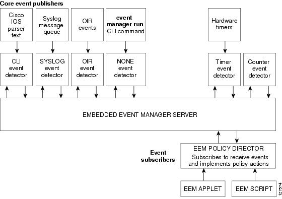
Event Detectors
EEM software programs known as event detectors determine when an EEM event occurs. Event detectors are separate systems that provide an interface between the agent being monitored, for example SNMP, and the EEM polices where an action can be implemented. Event detectors are generated only by the active switch. CLI and routing processes also run only from the active switch.
Note![]() On a Catalyst 3750 switch stack, the stack member switch does not generate events and does not support memory threshold notifications or IOSWdSysmon event detectors.
On a Catalyst 3750 switch stack, the stack member switch does not generate events and does not support memory threshold notifications or IOSWdSysmon event detectors.
EEM allows these event detectors:
- Application-specific event detector– Allows any EEM policy to publish an event.
- IOS CLI event detector– Generates policies based on the commands entered through the CLI.
- GOLD event detector– Publishes an event when a GOLD failure event is detected on a specified card and subcard.
- Counter event detector–Publishes an event when a named counter crosses a specified threshold.
- Interface counter event detector– Publishes an event when a generic Cisco IOS interface counter for a specified interface crosses a defined threshold. A threshold can be specified as an absolute value or an incremental value.For example, if the incremental value is set to 50 an event would be published when the interface counter increases by 50.
- None event detector– Publishes an event when the event manager run CLI command executes an EEM policy. EEM schedules and runs policies on the basis on an event specification within the policy itself. An EEM policy must be manually identified and registered before the event manager run command executes.
- Online insertion and removal event detector–Publishes an event when a hardware insertion or removal (OIR) event occurs.
- Resource threshold event detector– Generates policies based on global platform values and thresholds. Includes resources such as CPU utilization and remaining buffer capacity. Applies only to the active switch.
- SNMP event detector– Allows a standard SNMP MIB object to be monitored and an event to be generated when the object matches specified values or crosses specified thresholds.
- Syslog event detector– Allows for screening syslog messages for a regular expression pattern match. The selected messages can be further qualified, requiring that a specific number of occurrences be logged within a specified time. A match on a specified event criteria triggers a configured policy action.
- Timer event detector
Publishes events for these timers:
–![]() An absolute-time-of-day timer publishes an event when a specified absolute date and time occurs.
An absolute-time-of-day timer publishes an event when a specified absolute date and time occurs.
–![]() A countdown timer publishes an event when a timer counts down to zero.
A countdown timer publishes an event when a timer counts down to zero.
–![]() A watchdog timer publishes an event when a timer counts down to zero. The timer automatically resets itself to its initial value and starts to count down again.
A watchdog timer publishes an event when a timer counts down to zero. The timer automatically resets itself to its initial value and starts to count down again.
–![]() A CRON timer publishes an event by using a UNIX standard CRON specification to define when the event is to be published. A CRON timer never publishes events more than once per minute.
A CRON timer publishes an event by using a UNIX standard CRON specification to define when the event is to be published. A CRON timer never publishes events more than once per minute.
Publishes an event when one of these events occurs:
–![]() CPU utilization for a Cisco IOS process crosses a threshold.
CPU utilization for a Cisco IOS process crosses a threshold.
–![]() Memory utilization for a Cisco IOS process crosses a threshold.
Memory utilization for a Cisco IOS process crosses a threshold.
Two events can be monitored at the same time, and the event publishing criteria requires that one or both events cross their specified thresholds.
Embedded Event Manager Actions
EEM provides actions that occur in response to an event. EEM supports these actions:
- Modifying a named counter.
- Publishing an application-specific event.
- Generating an SNMP trap.
- Generating prioritized syslog messages.
- Reloading the Cisco IOS software.
- Reloading the switch stack. (Catalyst 3750 only)
- Reloading the active switch in the event of a changeover of the active switch. If this occurs, a new active switch is elected.
Embedded Event Manager Policies
EEM can monitor events and provide information, or take corrective action when the monitored events occur or a threshold is reached. An EEM policy is an entity that defines an event and the actions to be taken when that event occurs.
There are two types of EEM policies: an applet or a script. An applet is a simple policy that is defined within the CLI configuration. It is a concise method for defining event screening criteria and the actions to be taken when that event occurs. Scripts are defined on the networking device by using an ASCII editor. The script is then copied to the networking device and registered with EEM.
You use EEM to write and implement your own policies using the EEM policy tool command language (TCL) script. When you configure a TCL script on the active switch and the file is automatically sent to the member switches. The user-defined TCL scripts must be available in the member switches so that if the active switch changes, the TCL scripts policies continue to work.
Cisco enhancements to TCL in the form of keyword extensions facilitate the development of EEM policies. These keywords identify the detected event, the subsequent action, utility information, counter values, and system information.
For complete information on configuring EEM policies and scripts, see the Cisco IOS Network Management Configuration Guide, Release 12.4T.
Embedded Event Manager Environment Variables
EEM uses environment variables in EEM policies. These variables are defined in a EEM policy tool command language (TCL) script by running a CLI command and the event manager environment command. These environment variables can be defined in EEM:
Defined by the user for a user-defined policy.
Defined by Cisco for a specific sample policy.
Defined by Cisco and can be read-only or read-write. The read-only variables are set by the system before an applet starts to execute. The single read-write variable, _exit_status, allows you to set the exit status for policies triggered from synchronous events.
Cisco-defined environment variables and Cisco system-defined environment variables might apply to one specific event detector or to all event detectors. Environment variables that are user-defined or defined by Cisco in a sample policy are set by using the event manager environment global configuration command. You must defined the variables in the EEM policy before you register the policy.
For information about the environmental variables that EEM supports, see the Cisco IOS Network Management Configuration Guide, Release 12.4T.
Configuring Embedded Event Manager
These sections contain this configuration information:
- Registering and Defining an Embedded Event Manager Applet
- Registering and Defining an Embedded Event Manager TCL Script
For complete information about configuring embedded event manager, see the Cisco IOS Network Management Configuration Guide, Release 12.4T.
Registering and Defining an Embedded Event Manager Applet
Beginning in privileged EXEC mode, perform this task to register an applet with EEM and to define the EEM applet using the event applet and action applet configuration commands.
Note![]() Only one event applet command is allowed in an EEM applet. Multiple action applet commands are permitted. If you do not specify the no event and no action commands, the applet is removed when you exit configuration mode.
Only one event applet command is allowed in an EEM applet. Multiple action applet commands are permitted. If you do not specify the no event and no action commands, the applet is removed when you exit configuration mode.
This example shows the output for EEM when one of the fields specified by an SNMP object ID crosses a defined threshold:
These examples show actions that are taken in response to an EEM event:
Registering and Defining an Embedded Event Manager TCL Script
Beginning in privileged EXEC mode, perform this task to register a TCL script with EEM and to define the TCL script and policy commands.
This example shows the sample output for the show event manager environment command:
This example shows a CRON timer environment variable, which is assigned by the software, to be set to every second minute, every hour of every day:
Displaying Embedded Event Manager Information
To display information about EEM, including EEM registered policies and EEM history data, see the Cisco IOS Configuration Fundamentals and Network Management Command Reference, Release 12.3T.
Updates to the Catalyst 2960 Switch Software Configuration Guide
These are the updates to the Catalyst 2960 Switch Software Configuration Guide:
- This information was added to the “Setting the Type of a Dual-Purpose Uplink Port” section in the “Configuring Interface Characteristics” chapter in the Catalyst 2960 Switch Software Configuration Guide :
When the media type of a dual-purpose uplink port is auto-select, you cannot configure the speed and duplex settings. The interface auto-negotiates with its link partner. To configure the speed and duplex parameters, select the media type as either rj45 or sfp by using the media-type { rj45 | sfp } interface configuration command.
- The “Configuring IPv6 ACLs" chapter has been removed. The feature is not supported on the Catalyst 2960 switches. The current version of the software configuration guide is at this URL:
http://www.cisco.com/en/US/products/ps6406/products_configuration_guide_book09186a0080875183.html
Updates to the Catalyst 3750 Switch Command Reference Guide
The usage guidelines for the set and unset bootloader commands in the Catalyst 3750 Switch Software Command Reference command reference are incorrect.
These are the correct usage guidelines for the set command:
Environment variables are case sensitive and must be entered as documented.
Environment variables that have values are stored in flash memory outside of the flash file system.
Under normal circumstances, it is not necessary to alter the setting of the environment variables.
These are the correct guidelines for the unset command:
Under normal circumstances, it is not necessary to alter the setting of the environment variables.
The MANUAL_BOOT environment variable can also be reset by using the no boot manual global configuration command.
The BOOT environment variable can also be reset by using the no boot system global configuration command.
The ENABLE_BREAK environment variable can also be reset by using the no boot enable-break global configuration command.
The HELPER environment variable can also be reset by using the no boot helper global configuration command.
The CONFIG_FILE environment variable can also be reset by using the no boot config-file global configuration command.
The HELPER_CONFIG_FILE environment variable can also be reset by using the no boot helper-config-file global configuration command.
For Catalyst 3750-E and 3750 switches, the SWITCH_PRIORITY environment variable can also be set by using the switch stack-member-number priority priority-number global configuration command.
The bootloader prompt string (PS1) can be up to 120 printable characters except the equal sign (=).
These are the correct guidelines for the unset command:
Under normal circumstances, it is not necessary to alter the setting of the environment variables.
The MANUAL_BOOT environment variable can also be reset by using the no boot manual global configuration command.
The BOOT environment variable can also be reset by using the no boot system global configuration command.
The ENABLE_BREAK environment variable can also be reset by using the no boot enable-break global configuration command.
The HELPER environment variable can also be reset by using the no boot helper global configuration command.
The CONFIG_FILE environment variable can also be reset by using the no boot config-file global configuration command.
The HELPER_CONFIG_FILE environment variable can also be reset by using the no boot helper-config-file global configuration command.
Updates to the Catalyst 2960 Switch Command Reference Guide
The Catalyst 2970 switch no longer supports the snmp-server enable traps rtr global configuration command. Though visible in the command-line help strings, the rtr keyword is not supported.
New System Messages
These messages were added to all of the system message guides:
Error Message DOT1X_SWITCH-5-ERR_ADDING_ADDRESS: Unable to add address [enet] on [chars]Explanation The client MAC address could not be added to the MAC address table because the hardware memory is full or the address is a secure address on another port. [enet] is the supplicant MAC address, and [chars] is the interface. This message might appear if the IEEE 802.1x feature is enabled.
Recommended Action If the hardware memory is full, remove some of the dynamic MAC addresses. If the client address is on another port, manually remove it from that port.
Error Message SPANTREE-6-PORTADD_ALL_VLANS: [chars] added to all VlansExplanation The interface has been added to all VLANs. [chars] is the added interface.
Recommended Action No action is required.
Error Message SPANTREE-6-PORTDEL_ALL_VLANS: [chars] deleted from all VlansExplanation The interface has been deleted from all VLANs. [chars] is the deleted interface.
Recommended Action No action is required.
Error Message SW_VLAN-6-VTP_DOMAIN_NAME_CHG: VTP domain name changed to [chars].Explanation The VLAN Trunking Protocol (VTP) domain name was changed through the configuration to the name specified in the message. [chars] is the changed domain name.
Recommended Action No action is required.
These messages were added to the Catalyst 3750 and 3560 system message guides:
Error Message PLATFORM_HCEF-3-ADJ: [chars]Explanation This message appears when an unsupported feature is configured on a switch running Cisco IOS Release 12.2(25)SE. [chars] is the error message.
Recommended Action Determine if a generic routing encapsulation (GRE) tunnel or the ip cef accounting global configuration command are configured. Only Distance Vector Multicast Routing Protocol (DVMRP) tunnels are supported. If the GRE tunnel is configured, remove the tunnel, or upgrade the switch software to a Cisco IOS release when the GRE feature is needed. If the ip cef accounting command is configured, remove it by using the no ip cef accounting global configuration command.
Note![]() Cisco IOS Release12.2(25)SEB2 does not support the ip cef accounting command.
Cisco IOS Release12.2(25)SEB2 does not support the ip cef accounting command.
Explanation A more specific prefix could not be programmed into Ternary Content Addressable Memory (TCAM) and is covered by a less specific prefix. This could be a temporary condition. The output of the show platform ipv6 unicast retry route privileged EXEC command lists the failed prefixes.
Recommended Action No action is required.
Error Message PLATFORM_UCAST-6-PREFIX: One or more, more specific prefixes could not be programmed into TCAM and are being covered by a less specific prefixExplanation A more specific prefix could not be programmed into Ternary Content Addressable Memory (TCAM) and is covered by a less specific prefix. This could be a temporary condition. The output of the show platform ip unicast failed route privileged EXEC command lists the failed prefixes.
Changed System Messages
The error explanation and action has changed for this system message:
Error Message EC-5-CANNOT_BUNDLE1: Port-channel [chars] is down, port [chars] will remain stand-alone.Explanation The aggregation port is down. The port remains standalone until the aggregation port is up. The first [chars] is the EtherChannel. The second [chars] is the port number.
Recommended Action Ensure that the other ports in the bundle have the same configuration.
Error Message ILPOWER-3-CONTROLLER_PORT_ERR:Controller port error, Interface Fa0/7:Power given, but link is not up.
Note![]() This message applies only to the Catalyst 3750 and 3560 switches.
This message applies only to the Catalyst 3750 and 3560 switches.
Explanation The inline-power-controller reported an error on an interface.
Recommended Action Enter the shutdown and no shutdown interface configuration commands on the affected interfaces. Upgrade to Cisco IOS Release12.1(14)EA1 or later, which provides an electrostatic discharge (ESD) recovery mechanism.
Updates to the Catalyst 3750, 3560, 2970, and 2960 Hardware Installation Guide
Cisco Ethernet Switches are equipped with cooling mechanisms, such as fans and blowers. However, these fans and blowers can draw dust and other particles, causing contaminant buildup inside the chassis, which can result in a system malfunction.
You must install this equipment in an environment as free as possible from dust and foreign conductive material (such as metal flakes from construction activities).
These standards provide guidelines for acceptable working environments and acceptable levels of suspended particulate matter:
–![]() Network Equipment Building Systems (NEBS) GR-63-CORE
Network Equipment Building Systems (NEBS) GR-63-CORE
–![]() National Electrical Manufacturers Association (NEMA) Type 1
National Electrical Manufacturers Association (NEMA) Type 1
–![]() International Electrotechnical Commission (IEC) IP-20
International Electrotechnical Commission (IEC) IP-20
This applies to all Cisco Ethernet switches except for these compact models:
–![]() Catalyst 3560-8PC switch—8 10/100 PoE ports and 1 dual-purpose port (one 10/100/1000BASE-T copper port and one SFP module slot)
Catalyst 3560-8PC switch—8 10/100 PoE ports and 1 dual-purpose port (one 10/100/1000BASE-T copper port and one SFP module slot)
–![]() Catalyst 2960-8TC switch—8 10/100BASE-T Ethernet ports and 1 dual-purpose port (one 10/100/1000BASE-T copper port and one SFP module slot)
Catalyst 2960-8TC switch—8 10/100BASE-T Ethernet ports and 1 dual-purpose port (one 10/100/1000BASE-T copper port and one SFP module slot)
–![]() Catalyst 2960G-8TC switch—7 10/100/100BASE-T Ethernet ports and 1 dual-purpose port (one 10/100/1000BASE-T copper port and one SFP module slot)
Catalyst 2960G-8TC switch—7 10/100/100BASE-T Ethernet ports and 1 dual-purpose port (one 10/100/1000BASE-T copper port and one SFP module slot)
Updates to the Catalyst 3750 Getting Started Guide
The Express Setup configuration windows were updated in the getting started guide. This is the complete procedure:
Running Express Setup
When you first set up the switch, you should use Express Setup to enter the initial IP information. This enables the switch to connect to local routers and the Internet. You can then access the switch through the IP address for further configuration.
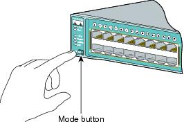
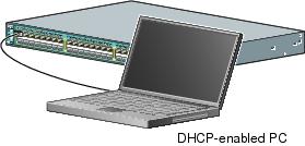
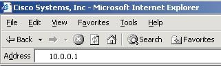
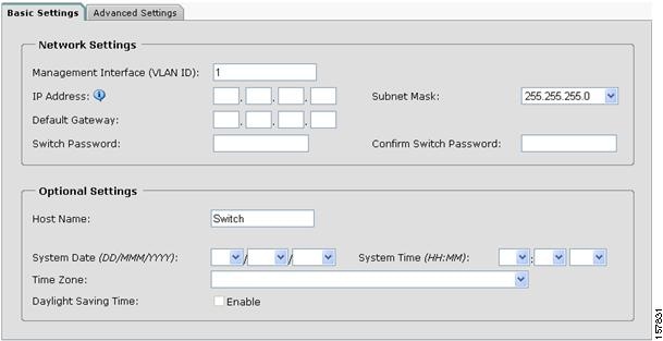
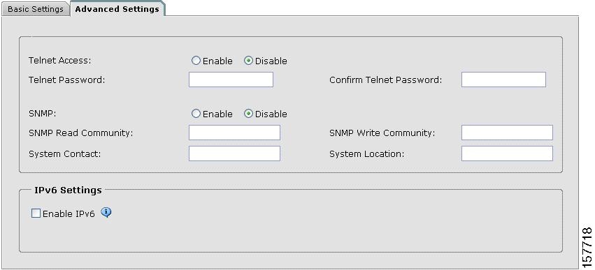
Statement 370—Attaching the Cisco RPS to the RPS Receptacle


Related Documentation
These documents provide complete information about the Catalyst 3750, 3560, 2970, and 2960 switches and the Cisco EtherSwitch service modules and are available at Cisco.com:
- http://www.cisco.com/en/US/products/hw/switches/ps5023/tsd_products_support_series_home.html
- http://www.cisco.com/en/US/products/hw/switches/ps5528/tsd_products_support_series_home.html
- http://www.cisco.com/en/US/products/hw/switches/ps5206/tsd_products_support_series_home.html
- http://www.cisco.com/en/US/products/ps6406/tsd_products_support_series_home.html
You can order printed copies of documents with a DOC-xxxxxx= number from the Cisco.com sites and from the telephone numbers listed in the URL referenced in the Obtaining Documentation, Obtaining Support, and Security Guidelines section.
These documents provide complete information about the Catalyst 3750 switches and the Cisco EtherSwitch service modules:
- Catalyst 3750 Switch Software Configuration Guide (not orderable but available on Cisco.com)
- Catalyst 3750 Switch Command Reference ( not orderable but available on Cisco.com)
- Catalyst 3750, 3560, 3550, 2970, and 2960 Switch System Message Guide (not orderable but available on Cisco.com)
- Catalyst 3750 Switch Hardware Installation Guide (not orderable but available on Cisco.com)
- Catalyst 3750 Getting Started Guide ( order number DOC-7816663=)
- Catalyst 3750 Integrated Wireless LAN Controller Switch Getting Started Guide ( order number DOC-7817540=)
- Regulatory Compliance and Safety Information for the Catalyst 3750 Switch (order number DOC-7816664)
These documents provide complete information about the Catalyst 3750G Integrated Wireless LAN Controller Switch and the integrated wireless LAN controller and are available at cisco.com:
- Catalyst 3750 Integrated Wireless LAN Controller Switch Getting Started Guide ( order number DOC-7817540=)
- Release Notes for Cisco Wireless LAN Controller and Lightweight Access Point, Release 4.0.x.0
- Cisco Wireless LAN Controller Configuration Guide, Release 4.0
- Cisco W ireless LAN Controller Command Reference, Release 4.0
These documents provide complete information about the Catalyst 3560 switches:
- Catalyst 3560 Switch Software Configuration Guide (not orderable but available on Cisco.com)
- Catalyst 3560 Switch Command Reference (not orderable but available on Cisco.com)
- Catalyst 3750, 3560, 3550, 2970, and 2960 Switch System Message Guide (not orderable but available on Cisco.com)
- Catalyst 3560 Switch Hardware Installation Guide (not orderable but available on Cisco.com)
- Catalyst 3560 Switch Getting Started Guide ( order number DOC-7816660=)
- Regulatory Compliance and Safety Information for the Catalyst 3560 Switch (order number DOC-7816665)
These documents provide complete information about the Catalyst 2970 switches:
- Catalyst 2970 Switch Software Configuration Guide (not orderable but available on Cisco.com)
- Catalyst 2970 Switch Command Reference ( not orderable but available on Cisco.com)
- Catalyst 3750, 3560, 3550, 2970, and 2960 Switch System Message Guide (not orderable but available on Cisco.com)
- Catalyst 2970 Switch Hardware Installation Guide (not orderable but available on Cisco.com)
- Catalyst 2970 Switch Getting Started Guide (order number DOC-7816685=)
- Regulatory Compliance and Safety Information for the Catalyst 2970 Switch (order number DOC-7816686=)
These documents provide complete information about the Catalyst 2960 switches:
- Catalyst 2960 Switch Software Configuration Guide (not orderable but available on Cisco.com)
- Catalyst 2960 Switch Command Reference ( not orderable but available on Cisco.com)
- Catalyst 3750, 3560, 3550, 2970, and 2960 Switch System Message Guide (not orderable but available on Cisco.com)
- Catalyst 2960 Switch Hardware Installation Guide (not orderable but available on Cisco.com)
- Catalyst 2960 Switch Getting Started Guide (order number DOC-7816879=)
Note![]() The above getting started guide, orderable in print, provides information in all supported languages. Listed below are online-only getting started guides in the individual languages.
The above getting started guide, orderable in print, provides information in all supported languages. Listed below are online-only getting started guides in the individual languages.
- Catalyst 2960 Switch Getting Started Guide —English (not orderable but available on Cisco.com)
- Catalyst 2960 Switch Getting Started Guide —Chinese (Simplified) (not orderable but available on Cisco.com)
- Catalyst 2960 Switch Getting Started Guide —French (not orderable but available on Cisco.com)
- Catalyst 2960 Switch Getting Started Guide —German (not orderable but available on Cisco.com)
- Catalyst 2960 Switch Getting Started Guide —Italian (not orderable but available on Cisco.com)
- Catalyst 2960 Switch Getting Started Guide —Japanese (not orderable but available on Cisco.com)
- Catalyst 2960 Switch Getting Started Guide —Spanish (not orderable but available on Cisco.com)
- Regulatory Compliance and Safety Information for the Catalyst 2960 Switch (order number DOC-7816880=)
For other information about related products, see these documents:
- Device manager online help (available on the switch)
- Getting Started with Cisco Network Assistant (not orderable but available on Cisco.com)
- Release Notes for Cisco Network Assistant (not orderable but available on Cisco.com)
- Cisco RPS 300 Redundant Power System Hardware Installation Guide (order number DOC-7810372=)
- Cisco RPS 675 Redundant Power System Hardware Installation Guide (order number DOC-7815201=)
- For more information about the Network Admission Control (NAC) features, see the Network Admission Control Software Configuration Guide (not orderable but available on Cisco.com)
- Cisco Small Form-Factor Pluggable Modules Installation Notes (order number DOC-7815160=)
- Cisco CWDM GBIC and CWDM SFP Installation Note (not orderable but available on Cisco.com)
- These compatibility matrix documents are available from this Cisco.com site:
http://www.cisco.com/en/US/products/hw/modules/ps5455/products_device_support_tables_list.html
–![]() Cisco Gigabit Ethernet Transceiver Modules Compatibility Matrix (not orderable but available on Cisco.com)
Cisco Gigabit Ethernet Transceiver Modules Compatibility Matrix (not orderable but available on Cisco.com)
–![]() Cisco 100-Megabit Ethernet SFP Modules Compatibility Matrix (not orderable but available on Cisco.com)
Cisco 100-Megabit Ethernet SFP Modules Compatibility Matrix (not orderable but available on Cisco.com)
–![]() Cisco Small Form-Factor Pluggable Modules Compatibility Matrix (not orderable but available on Cisco.com)
Cisco Small Form-Factor Pluggable Modules Compatibility Matrix (not orderable but available on Cisco.com)
–![]() Compatibility Matrix for 1000BASE-T Small Form-Factor Pluggable Modules (not orderable but available on Cisco.com)
Compatibility Matrix for 1000BASE-T Small Form-Factor Pluggable Modules (not orderable but available on Cisco.com)
Obtaining Documentation, Obtaining Support, and Security Guidelines
For information on obtaining documentation, obtaining support, providing documentation feedback, security guidelines, and also recommended aliases and general Cisco documents, see the monthly What’s New in Cisco Product Documentation, which also lists all new and revised Cisco technical documentation, at:
http://www.cisco.com/en/US/docs/general/whatsnew/whatsnew.html
Cisco and the Cisco logo are trademarks or registered trademarks of Cisco and/or its affiliates in the U.S. and other countries. To view a list of Cisco trademarks, go to this URL: www.cisco.com/go/trademarks. Third-party trademarks mentioned are the property of their respective owners. The use of the word partner does not imply a partnership relationship between Cisco and any other company. (1721R)
Any Internet Protocol (IP) addresses used in this document are not intended to be actual addresses. Any examples, command display output, and figures included in the document are shown for illustrative purposes only. Any use of actual IP addresses in illustrative content is unintentional and coincidental.
 Feedback
Contact Cisco
- Open a Support Case

- (Requires a Cisco Service Contract)