Catalyst 3650 Switch Getting Started Guide
Available Languages
Table Of Contents
Catalyst 3650 Switch Getting Started Guide
Installation Warning Statements
Securing the AC Power Cord (Optional)
Connecting the StackWise Cables
StackWise Cabling Configurations
Connecting to the Switch Ports
10/100/1000 or 10/100/1000 PoE+ Ports
SFP and SFP+ Transceiver Module Ports
Obtaining Documentation and Submitting a Service Request
Catalyst 3650 Switch Getting Started Guide
•
Securing the AC Power Cord (Optional)
•
•
•
•
About This Guide
This guide describes how to use Express Setup to initially configure your Catalyst 3650 switch. The guide also covers switch management options, installation, basic rack-mounting, stacking, port and module connections, and troubleshooting.

Note
For more installation and configuration information, see the Catalyst 3650 documentation on Cisco.com. For system requirements, important notes, limitations, open and resolved bugs, and documentation updates, see the Catalyst 3650 release notes on Cisco.com.
When using the online publications, refer to the documents that match the Cisco IOS software version running on the switch.
For translations of the warnings that appear in this publication, see the Regulatory Compliance and Safety Information for the Catalyst 3650 Switch on Cisco.com.
Shipping Box Contents
The shipping box contains the model of the switch you ordered and other components needed for installation, as shown in Figure 1. Some components are optional, depending on your order.
Note
Figure 1 Components Delivered in the Shipping Box

Catalyst 36501 switch2 (power supplies and fan modules not shown)3
Eight number-8 Phillips flat-head screws
(Optional) AC power cord2
Cable guide
Product documentation and compliance document
M4.0 x 20mm Phillips pan-head screw
Four rubber mounting feet
(Optional) RJ-45 console cable2
Ground lug screw and ring terminal
(Optional) USB console cable2
Two 19-inch mounting brackets
(Optional) StackWise (Stackwise-160) cable to connect a Catalyst 3650 switch to another Catalyst 3650 switch (0.5-meter, 1-meter, or 3-meter)2
Four number-12 pan-head screws
(Optional) Two StackWise (Stackwise-160) adapters2
Four number-10 pan-head screws
1 Catalyst 3650-48PS-L switch is shown. Your switch model might look different.
2 Item is orderable.
3 Fan modules are installed in the switch. Power supply modules are not installed in the switch.
Running Express Setup
Use Express Setup to enter the initial IP information. This action enables the switch to connect to local routers and the Internet. You can access the switch through the IP address for further configuration.
Note
You need this equipment:
•
•
•
Note
Step 1
Make sure that nothing is connected to the switch.
Step 2
During Express Setup, the switch acts as a DHCP server. If your PC or laptop has a static IP address, temporarily change your PC or laptop settings before you use DHCP.
Note
Step 3
Install the power supply modules. See the "Power Supply Installation" chapter in the Catalyst 3650 Switch Hardware Installation Guide for instructions.
http://www.cisco.com/go/cat3650_hw
Note
Step 4
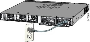
Power the switch.
AC power switches: Plug the AC power cord into the switch power supply and into a grounded AC outlet.
DC power switches: See the wiring instructions in the Catalyst 3650 Switch Hardware Installation Guide on Cisco.com:
Step 5
Observe the POST results. Approximately 30 seconds after the switch powers on, it begins the power-on self-test (POST), which can take up to 5 minutes to complete.
During POST, the SYSTEM LED blinks green. When POST is complete, the SYSTEM LED turns solid green. The ACTV LED is green if the switch is acting as the active switch.
Note
Troubleshooting:
If the SYST LED does not turn solid green, or turns amber, the switch failed the POST. Contact your Cisco representative or reseller.
Step 6
Press and hold the Mode button until all the LEDs next to the Mode button turn green.
You might need to hold the button for more than 3 seconds.
The switch is now in Express Setup mode.
Troubleshooting:
If the LEDs next to the Mode button blink when you press the button, release it. Blinking LEDs mean that the switch is already configured and cannot go into Express Setup mode. For more information, see the "Resetting the Switch" section.
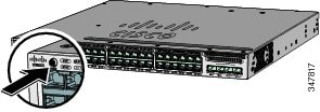
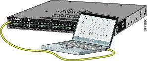
Step 7
Connect a Category 5 Ethernet cable to a port:
•
•
Connect the other end of the cable to the Ethernet port on your PC or laptop.
Wait until the port LEDs on the switch and your PC or laptop are green or blinking green. Green LEDs indicate a successful connection.
Troubleshooting:
If the port LEDs do not turn green after about 30 seconds, make sure that:
•
•
•
Step 8
Start a browser session on the PC or laptop, and enter the IP address https://10.0.0.1. When prompted, enter the default password, cisco.
Note
The Express Setup window appears.
Troubleshooting:
If the Express Setup window does not appear, make sure that any browser pop-up blockers or proxy settings are disabled and that any wireless client is disabled on your PC or laptop.
Step 9
Enter this information in the Network Settings fields:
Note
•
Note
•
•
•
•
Note
(Optional) Enter this information in the Ethernet Management Port Settings fields:
•
Step 10
(Optional) You can enter other administrative settings in the Optional Settings fields. You can enter the Optional Settings information now or enter it later using the Device Manager interface. For example, the optional administrative settings identify and synchronize the switch for enhanced management. NTP automatically synchronizes the switch clock with the network clock. You can manually set the system clock if the switch should have different settings.
Step 11
(Optional) You can select the Advanced Settings tab on the Express Setup window and enter the advanced settings now or enter them later using the Device Manager interface.
•
•
•
•
•
•
Note
Step 12
Click Submit to save your changes and to complete the initial setup.
After you click Submit:
•
•
For more information about Express Setup fields, see the online help for the Express Setup window.
Step 13
Disconnect the switch from the PC and laptop, and install the switch in your network. See the "Installing the Switch" section.
Step 14
If you changed the static IP address on your PC or laptop in Step 2, change it to the previously configured static IP address.
Step 15
See the "Managing the Switch" section for information about configuring and managing the switch.
To run Express Setup:
Managing the Switch
After completing Express Setup and installing the switch in your network, you can use these options for configuration:
Configuration Wizard
The Configuration Wizard is a Web-based controller user interface (UI) that lets you complete the initial wireless configuration after you configure the IP address, local username, and password or authorization using the authentication server. Using the Web UI, you can configure the controller, WLAN, and radios for all initial operations, establish management parameters, set security policies, access software management commands, configure system logs, and other tasks.
For more information on using the Configuration Wizard, see switch software configuration guide on Cisco.com
Device Manager
The simplest way to manage the switch is by using Device Manager in the switch memory. Use Device Manager for basic switch configuration and monitoring. This web interface offers quick configuration and monitoring. You can access it through a web browser.
To display Device Manager:
Step 1
Step 2
Troubleshooting:
If Device Manager does not appear:
•
•
•
•
•
Cisco Network Assistant
Cisco Network Assistant is a software program that you download from Cisco.com and run on your PC or laptop. It offers advanced options for configuring and monitoring multiple devices, including switches, switch clusters, switch stacks, routers, and access points. Network Assistant is free—there is no charge to download, install, or use it.
To use Cisco Network Assistant:
Step 1
Note
Step 2
Step 3
Step 4
Step 5
See the Cisco Network Assistant online help and the Cisco Network Assistant Getting Started Guide for more information.
Command-Line Interface
You can enter Cisco IOS commands and parameters through the CLI by using one of these options:
Note
USB Console Port
Note
Step 1
Step 2
Step 3
Step 4
RJ-45 Console Port
Step 1
Step 2
Step 3
Step 4
Ethernet Management Port
Step 1
Step 2
Step 3
Step 4
Other Management Options
Cisco Prime Infrastructure combines the wireless functionality of Cisco Prime Network Control System (NCS) and the wired functionality of Cisco Prime LAN Management Solution (LMS) with application performance monitoring and troubleshooting capabilities of Cisco Prime Assurance Manager. For more information, see the Cisco Prime Infrastructure documentation on Cisco.com.
See the "Accessing Help Online" section for supporting documentation.
Installing the Switch
This section describes basic 19-inch rack-mounting. See the Catalyst 3650 Switch Hardware Installation Guide for other optional bracket information. The illustrations show a Catalyst 3650-48PS-L switch. You can install and connect other Catalyst 3650 switches as shown.
Equipment That You Need
•
•
Before You Begin
Before installing the switch, verify that these guidelines are met:
•
•
•
Note
•
–
–
•
•
•
Note
•
•
•
•
•
Installation Warning Statements
Translations of these warning statements appear in the Regulatory Compliance and Safety Information for the Catalyst 3650 Switch document on Cisco.com.
Warning
Warning
113°F (45°C) Statement 1047
Warning
Warning
3 in. (7.6 cm) Statement 1076
Note
Note
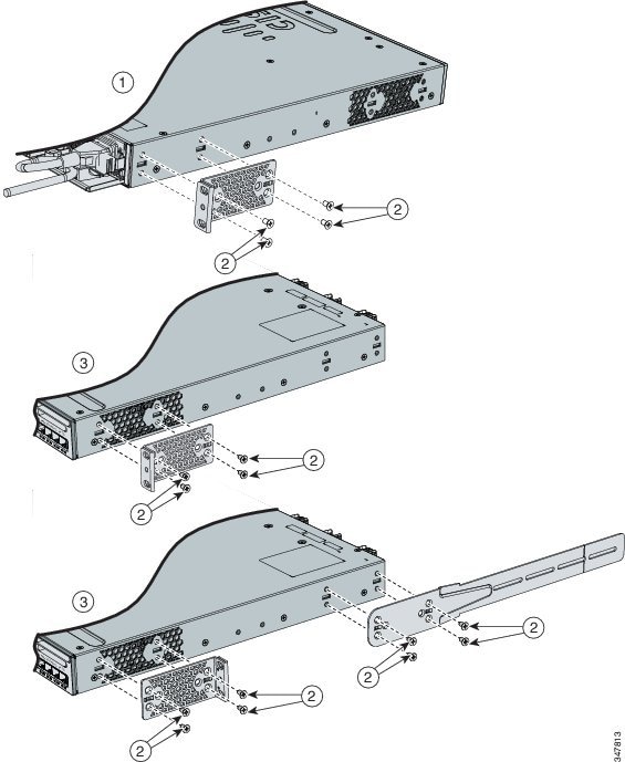
Attaching the Brackets
Use four number-8 Phillips flat-head screws to attach the long side of each bracket to the switch in one of these mounting positions.
Figure 2 Attaching the Brackets to the Switch
Rack-Mount the Switch
Use the four number-12 Phillips machine screws to attach the brackets to the rack. Use the black Phillips machine screw to attach the cable guide to the left or right bracket.
Figure 3 Attaching the Brackets to the Rack
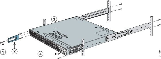
Phillips machine screw, black
Front-mounting position
Cable guide
Number-12 or number-10 Phillips machine screws
Install the power supply modules if needed.
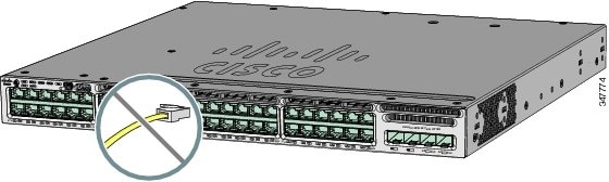
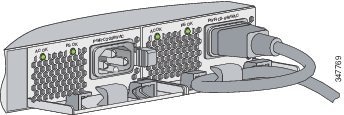
Securing the AC Power Cord (Optional)
Make a loop in the power cord and thread it through the power cord retainer. Connect the power cord to the power supply.
Figure 4 Securing the AC Power Cord
Connecting the StackWise Cables
You can stack the Catalyst 3650 switch with other Catalyst 3650 switches. Before connecting the StackWise cables, review the "Planning a Switch Data Stack" section in the Catalyst 3650 Switch Hardware Installation Guide. Always use Cisco-approved StackWise cables to connect the switches.

Caution
Step 1
A StackWise adapter must be installed in the StackWise port to enable stacking. The default setup is with StackWise adapter blanks installed in the StackWise ports. If StackWise stacking was ordered with the switch, StackWise adapters are already installed in the StackWise ports, and you can proceed to step 4.
Step 2
Step 3
Note
Step 4
a.
b.
c.
Step 5
Figure 5 Removing the StackWise Adapter Blank
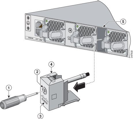
Figure 6 Inserting the StackWise Adapter into the StackWise Port
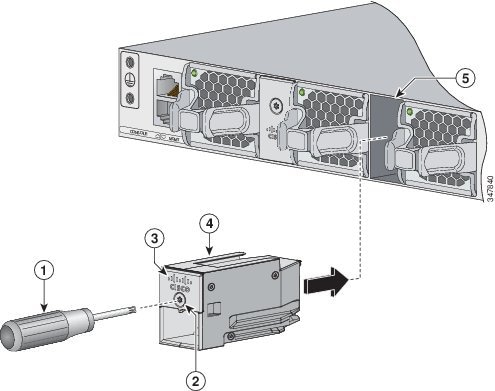
Figure 7 Inserting the Cable Connector into the StackWise Adapter
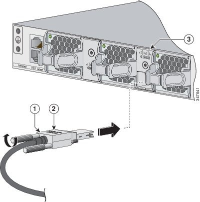
When you need to remove the StackWise cable from the connector, make sure to fully unscrew the correct screws. When the connectors are not being used, replace the dust covers.
Note
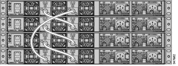
StackWise Cabling Configurations
The Catalyst 3650 switch can be stacked with other Catalyst 3650 switches.
Note
This illustration shows a recommended configuration making connections using 0.5-meter StackWise cables.
For other configuration examples, see the Catalyst 3650 Switch Hardware Installation Guide on Cisco.com at:
http://www.cisco.com/go/cat3650_hw
Figure 8 Example of a StackWise Cabling Configuration
Connecting to the Switch Ports
10/100/1000 or 10/100/1000 PoE+ Ports
When you connect to servers, workstations, IP phones, wireless access points, and routers:
•
•
•
In some switch models, the 10/100/1000 ports support Power over Ethernet (PoE) and PoE+.
•
•
For more details, see the Catalyst 3650 Switch Hardware Installation Guide on Cisco.com at:
http://www.cisco.com/go/cat3650_hw
Note
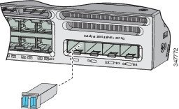
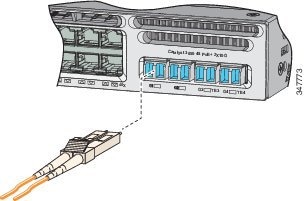
SFP and SFP+ Transceiver Module Ports
Use only Cisco SFP transceiver modules with the switch. For a list of supported modules, see the Catalyst 3650 Switch Hardware Installation Guide. For detailed instructions on installing, removing, and connecting to SFP transceiver modules, see the SFP and SFP+ transceivers module documentation.
Verify Port Connectivity
After you connect a device to the switch port, the port LED turns amber for about 30 seconds while the switch establishes a link. The LED turns green when the switch and the attached device are linked. If the LED is off, the device might not be turned on, or there might a problem with the cable or with the adapter installed in the device.
Troubleshooting
This section includes Express Setup troubleshooting, how to reset the switch, how to access help online, and where to find more information.
Express Setup
If Express Setup does not run or if the Express Setup page does not appear in your browser:
Resetting the Switch
Caution
To reset the switch to the factory defaults:
Step 1
Step 2
Step 3
Accessing Help Online
Look for a solution to your problem in the troubleshooting section of the Catalyst 3650 Switch Hardware Installation Guide or the Catalyst 3650 Switch Software Configuration Guide on Cisco.com. You can also access the Cisco Technical Support and Documentation website for a list of known hardware problems and extensive troubleshooting documentation.
Obtaining Documentation and Submitting a Service Request
For information about obtaining documentation, submitting a service request, and gathering additional information, see the monthly What's New in Cisco Product Documentation, which also lists all new and revised Cisco technical documentation, at:
http://www.cisco.com/en/US/docs/general/whatsnew/whatsnew.html
Subscribe to the What's New in Cisco Product Documentation as a Really Simple Syndication (RSS) feed and set content to be delivered directly to your desktop using a reader application. The RSS feeds are a free service and Cisco currently supports RSS Version 2.0.
Related Documentation
Before installing or upgrading the switch, refer to the switch release notes.
•
http://www.cisco.com/go/cat3650_docs
•
http://www.cisco.com/en/US/products/hw/modules/ps5455/tsd_products_support_series_home.html
•
https://www.cisco.com/cgi-bin/Support/Errordecoder/index.cgi
Cisco and the Cisco logo are trademarks or registered trademarks of Cisco and/or its affiliates in the U.S. and other countries. To view a list of Cisco trademarks, go to this URL: www.cisco.com/go/trademarks. Third-party trademarks mentioned are the property of their respective owners. The use of the word partner does not imply a partnership relationship between Cisco and any other company. (1110R)
Any Internet Protocol (IP) addresses used in this document are not intended to be actual addresses. Any examples, command display output, and figures included in the document are shown for illustrative purposes only. Any use of actual IP addresses in illustrative content is unintentional and coincidental.
© 2013 Cisco Systems, Inc. All rights reserved.

 Feedback
Contact Cisco
- Open a Support Case

- (Requires a Cisco Service Contract)