Release Notes for the Catalyst 3550-24-DC Switch, Cisco IOS Release 12.2(52)SE
Available Languages
Table Of Contents
Release Notes for the Catalyst 3550-24-DC Multilayer Switch, Cisco IOS Release 12.2(52)SE
Device Manager System Requirements
Finding the Software Version and Feature Set Running on the Switch
Deciding Which Files to Download from Cisco.com
Upgrading a Switch by Using Device Manager or Network Assistant
Upgrading a Switch by Using the CLI
Upgrading with a Nondefault System MTU Setting
Recovering from a Software Failure
Cisco IOS Limitations and Restrictions
Updates for the Software Configuration Guide
Updates for the Command Reference
Updates for the Regulatory Compliance and Safety Information for the Catalyst 3550 Multilayer Switch
Update to the Hardware Installation Guide
Update to the Getting Start Guide
Obtaining Documentation, Obtaining Support, and Security Guidelines
Release Notes for the Catalyst 3550-24-DC Multilayer Switch, Cisco IOS Release 12.2(52)SE
October 1, 2009
Cisco IOS Release 12.2(52)SE and later runs only on the Catalyst 3550-24-DC multilayer switch.
These release notes include important information about Cisco IOS Release 12.2(52)SE and later and any limitations, restrictions, and caveats that apply to them. Verify that these are the correct release notes for your switch:
•
If you are installing a new switch, refer to the Cisco IOS release label on the rear panel of your switch.
•
•
For the complete list of Catalyst 3550 switch documentation, see the "Related Documentation" section.
You can download the switch software from this site (registered Cisco.com users with a login password):
http://tools.cisco.com/support/downloads/go/MDFTree.x?butype=switches
This Cisco IOS release is part of a special release of Cisco IOS software that is not released on the same 8-week maintenance cycle that is used for other platforms. As maintenance releases and future Cisco IOS releases become available, they will be posted to Cisco.com in the Cisco IOS software area.
Contents
This information is in the release notes:
•
•
•
•
•
•
System Requirements
The system requirements for this release are described in these sections:
•
•
Hardware Supported
Table 1 lists the hardware supported by this release.
Table 1 Supported Hardware
Catalyst 3550-24-DC
24 autosensing 10/100 Ethernet ports, 2 GBIC-based Gigabit Ethernet slots, and an on-board DC power converter
GBIC modules
•
•
•
•
•
•
•
1 CWDM = coarse wavelength-division multiplexing
2 DWDM = dense wavelength-division multiplexing
Device Manager System Requirements
These sections describe the hardware and software requirements for using the device manager:
•
•
Hardware Requirements
Table 2 lists the minimum hardware requirements for running the device manager.
Table 2 Minimum Hardware Requirements
233 MHz minimum1
512 MB2
256
1024 x 768
Small
1 We recommend 1 GHz.
2 We recommend 1 GB DRAM.
Software Requirements
These are the supported operating systems and browsers for the device manager:
•
•
The device manager verifies the browser version when starting a session, and it does not require a plug-in.
Cluster Compatibility
You cannot create and manage switch clusters through the device manager. To create and manage switch clusters, use the command-line interface (CLI) or the Network Assistant application.
When creating a switch cluster or adding a switch to a cluster, follow these guidelines:
•
•
•
For additional information about clustering, see the Getting Started with Cisco Network Assistant and the Release Notes for Cisco Network Assistant, the software configuration guide, and the command reference.
CNA Compatibility
Cisco IOS 12.2(46)SE and later is only compatible with Cisco Network Assistant (CNA) 5.0 and later. You can download Cisco Network Assistant from this URL:
http://www.cisco.com/pcgi-bin/tablebuild.pl/NetworkAssistant
For more information about Cisco Network Assistant, see the Release Notes for Cisco Network Assistant on Cisco.com.
Upgrading the Switch Software
Before downloading software from Cisco.com to upgrade the switch software, read this section for important information:
•
•
•
•
•

Caution
When you upgrade a switch, the switch continues to operate while the new software is copied to flash memory. If flash memory has enough space, the new image is copied to the selected switch but does not replace the running image until you reboot the switch. If a failure occurs during the copy process, you can still reboot your switch by using the old image. If flash memory does not have enough space for two images, the new image is copied over the existing one. Features provided by the new software are not available until you reload the switch.
If a failure occurs while copying a new image to the switch, and the old image has already been deleted, see the "Recovering from Corrupted Software" section in the "Troubleshooting" chapter of the software configuration guide.
Finding the Software Version and Feature Set Running on the Switch
The Cisco IOS image is stored as a bin file in a directory that is named with the Cisco IOS release. A subdirectory contains the files needed for web management. The image is stored on the system board flash device (flash:).
You can use the show version privileged EXEC command to see the software version that is running on your switch. The second line displays C3550-ipbase9-mz for the IP services image (formerly known as the EMI) or C3550-ipbase-mz for the IP base image (formerly known as the SMI).

Note
You can also use the dir filesystem: privileged EXEC command to see the directory names of other software images that you might have stored in flash memory.
Deciding Which Files to Download from Cisco.com
Cisco IOS Release 12.2(25)SEA and earlier referred to the image that provides Layer 2+ features and basic Layer 3 routing features as the standard multilayer image (SMI). The image that provides full Layer 3 routing features and advanced features was referred to as the enhanced multilayer image (EMI).
Cisco IOS Release 12.2(25)SEB and later refers to the SMI as the IP base image and the EMI as the IP services image. Table 3 lists the different file-naming conventions before and after Cisco IOS Release 12.2(25)SEB.
The upgrade procedures in these release notes describe how to perform the upgrade by using a combined tar file. This file contains both the Cisco IOS image file and the files needed for the embedded device manager. To upgrade the switch through the command-line interface (CLI), use the tar file and the archive download-sw privileged EXEC command.
Table 4 lists the software filenames for this release. These files are posted on Cisco.com.
Catalyst 3550 switches are supported by either the IP base image or the IP services image. All Catalyst 3550 Gigabit Ethernet switches are shipped with the IP services image installed. Catalyst 3550 Fast Ethernet switches are shipped with either the IP base image or the IP services image installed. After initial deployment, you can order the IP services Image Upgrade kit to upgrade the Catalyst 3550 Fast Ethernet switches from the IP base image to the IP services image.
Archiving Software Images
Before upgrading your switch software, make sure that you have archived copies of the current Cisco IOS release and the Cisco IOS release to which you are upgrading. You should keep these archived images until you have upgraded all devices in the network to the new Cisco IOS image and until you have verified that the new Cisco IOS image works properly in your network.
Cisco routinely removes old Cisco IOS versions from Cisco.com. See Product Bulletin 2863 for more information:
http://www.cisco.com/en/US/products/sw/iosswrel/ps5187/prod_bulletin0900aecd80281c0e.html
You can copy the bin software image file on the flash memory to the appropriate TFTP directory on a host by using the copy flash: tftp: privileged EXEC command.
Note
You can also configure the switch as a TFTP server to copy files from one switch to another without using an external TFTP server by using the tftp-server global configuration command. For more information about the tftp-server command, see the "Basic File Transfer Services Commands" section of the Cisco IOS Configuration Fundamentals Command Reference, Release 12.2 at this URL:
Upgrading a Switch by Using Device Manager or Network Assistant
You can upgrade switch software by using the device manager or Network Assistant. From the feature bar, choose Administration > Software Upgrade. For detailed instructions, click Help.
Note
Upgrading a Switch by Using the CLI
This procedure is for copying the combined tar file to the Catalyst 3550 switch. You copy the file to the switch from a TFTP server and extract the files. You can download an image file and replace or keep the current image. This procedure requires a configured TFTP server.
Caution
To download software, follow these steps:
Step 1
Step 2
Go to this URL, and follow the instructions to register on Cisco.com and download the appropriate files:
http://www.cisco.com/public/sw-center/sw-lan.shtml
To download the IP base image (formerly known as the SMI) and IP services image (formerly known as the EMI) files, select Catalyst 3550 software.
To obtain authorization and to download the cryptographic software files, select Catalyst 3550 3DES Cryptographic Software.
Step 3
Step 4
Step 5
Step 6
archive download-sw /overwrite /reload tftp:[[//location]/directory]/image-name.tarThe /overwrite option overwrites the software image in flash memory with the downloaded one.
The /reload option reloads the system after downloading the image unless the configuration has been changed and not been saved.
For //location, specify the IP address of the TFTP server.
For /directory/image-name.tar, specify the directory (optional) and the image to download. Directory and image names are case sensitive.
This example shows how to download an image from a TFTP server at 198.30.20.19 and to overwrite the image on the switch:
Switch# archive download-sw /overwrite tftp://198.30.20.19/c3550-i5q3l2-tar.122-50.SE1.tarYou can also download the image file from the TFTP server to the switch and keep the current image by replacing the /overwrite option with the /leave-old-sw option.
Upgrading with a Nondefault System MTU Setting
If the switch was running Cisco IOS Release 12.1(8)EA1c or earlier and you had used the system mtu global configuration command to configure a nondefault system maximum transmission unit (MTU) size on your switch, follow these steps to upgrade your switch to Cisco IOS Release 12.1(11)EA1 or later:
Step 1
Step 2
is 2000 bytes.Step 3
Step 4
Step 5
Recovering from a Software Failure
If the software fails, you can reload the software. For detailed recovery procedures, see the "Troubleshooting" chapter in the software configuration guide.
Installation Notes
You can assign IP information to your switch by using one of these methods:
•
•
•
•
New Features
These sections describe the new supported hardware and the new software features provided in this release:
•
•
New Hardware Features
For a list of supported hardware, see the "Hardware Supported" section.
New Software Features
There are no new software features in this release.
Limitations and Restrictions
You should review this section before you begin working with the switches. These are known Cisco IOS limitations that will not be fixed, and there is not always a workaround. Some features might not work as documented, and some features could be affected by recent changes to the switch hardware or software.
Cisco IOS Limitations and Restrictions
These sections describe the Cisco IOS limitations for features on the switch:
IEEE 802.1x
These are IEEE 802.1x limitations:
•
The workaround is to change the number of seconds between re-authentication attempts by using the dot1x timeout re-authperiod seconds global configuration command. (CSCdz38483)
•
The workaround is to reset the switch MTU value to the default value or to configure the same MTU value on the switch, the authentication server, and the intermediate devices. (CSCea05682)
ACLs
These are access control list (ACL) limitations. For ACL limitations with quality of service (QoS), see the "QoS" section.
•
There is no workaround. (CSCdx80751)
•
%FM-3-UNLOADING: Unloading input vlan label 1 feature from all TCAMsThere is no workaround. (CSCea25658)
Connected Devices
These are limitations related to connections with specific devices:
•
The workaround is to disable the Port Aggregation Protocol (PAgP) on both devices by using the channel-group channel-group-number mode on interface configuration command. PAgP negotiation between these two devices is not reliable. (CSCdt78727)
•
When the switch stops receiving power from the Cisco RPS and uses its own power supply to power the switch, pressing the Standby/Active button on the Cisco RPS might cause the switch to reload.
Note
There is no workaround. (CSCdx81023)
•
There is no workaround. (CSCdx90515)
•
The workaround is remove the AC power supply, disconnect the Ethernet cable, and then reconnect the Ethernet cable. This ensures that the switch uses inline power. (CSCdz16265)
•
There is no workaround. (CSCdz37516)
•
The workaround is to configure the Catalyst 3550 Gigabit Ethernet interface with the spanning-tree portfast interface configuration command. (CSCea04746)
•
There is no workaround. (CSCea09786)
•
The workaround is to enter the switchport mode trunk interface configuration command on all of the GigaStack interfaces and to do one of these:
–
–
•
There is no known workaround. (CSCed73388)
•
There is no workaround. (CSCef17198)
•
Configuration
These are configuration limitations:
•
The workaround is to shut down the port, and to re-enable it by using the shutdown and no shutdown interface configuration commands. (CSCds84279)
•
The workaround, when you remove an EtherChannel group, is to enter the no shutdown interface configuration command on the interfaces that belonged to the port group to bring them back on line. (CSCdt10825)
•
There is no workaround. (CSCdt26928)
•
•
The workaround is to make sure that the management VLAN of all Catalyst 2900 XL or 3500 XL switches in the stack is set to VLAN 1. (CSCdv79737)
•
There is no workaround. (CSCdz06305)
•
The workaround is to not perform a ping from one interface to another on the same switch. (CSCea19301)
•
The workaround is to enter the no switchport block unicast interface configuration command on that specific interface. (CSCee93822)
•
The workaround is to configure the port for 10 Mb/s and half duplex or to connect a hub or a nonaffected device to the switch. (CSCed39091)
•
•
There is no workaround. (CSCsj21718)
DHCP
This is the DHCP limitation:
The DHCP option-82 format on the Catalyst 3550 switch is inconsistent with other Cisco switches. When the Catalyst 3550 switch is used as the relay agent with DHCP snooping and the option-82 feature using the VLAN-module-port (vlan-mod-port) format, the switch does not assign the correct value to the port identifier (circuit ID suboption). The value is offset by 1 from the actual interface module- and port-number values. The circuitID/port-identifier for Fast Ethernet and Gigabit Ethernet interfaces also have the same module-number but different port-number values. For example, on a Catalyst 3550-24 switch, fastethernet0/1 is reported as module 0/port 0 and gigabitethernet0/1 is reported as module 0/port 24.
There is no workaround. (CSCed29525)
EtherChannel
This is the EtherChannel limitations:
The switch might display tracebacks similar to this example when an EtherChannel interface port-channel type changes from Layer 2 to Layer 3 or the reverse:
15:50:11: %COMMON_FIB-4-FIBNULLHWIDB: Missing hwidb for fibhwidb Port-channel1 (ifindex
1632) -Traceback= A585C B881B8 B891CC 2F4F70 5550E8 564EAC 851338 84AF0C 4CEB50 859DF4
A7BF28 A98260 882658 879A58
There is no workaround. (CSCsh12472)
HSRP
This is the Hot Standby Router Protocol (HSRP) limitation:
After the no interface tunnel0 global configuration command is entered to remove the tunnel interface, the output from the show running-config privileged EXEC command still shows the tunnel interface that was removed.
This can occur if HSRP interface tracking is configured on another interface to track a tunnel interface, if the no interface command was entered before the HSRP tracking configuration was removed, or if the no standby tunnel0 global configuration command was entered on the other interface to disable tracking.
These are the workarounds:
•
•
IGMP
These are the IGMP limitations:
•
There is no workaround. (CSCdt27705)
•
There is no workaround. (CSCdv73626)
•
There is no workaround. (CSCdv79832)
•
There is no workaround. (CSCee16865)
•
Use one of these workarounds:
–
–
IP
This is the IP limitation:
•
The workaround is to not set an ARP timeout value lower than 120 seconds. (CSCea21674)
MAC Addressing
These are MAC address limitations:
•
There is no workaround. (CSCdz75459)
•
There is no workaround. (CSCed12004)
•
There is no workaround. (CSCef15178)
MIBs
These are MIB limitations:
•
The workaround is to use the value 1 to represent module 0. (CSCdw71848)
•
There is no workaround. (CSCdz87897)
Multicasting
These are the multicasting limitations:
•
After updating a multicast boundary, the workaround is to use the clear ip mroute privileged EXEC command to delete any existing multicast routes that violate the updated boundary. (CSCdr79083)
•
The workaround is to not trust the counter during this transient state. (CSCds61396)
•
There is no workaround. (CSCdt06418)
•
There is no workaround. (CSCdt48002)
•
The workaround is to enter the clear ip mroute privileged EXEC command to force the change to the shared tree. (CSCdt60412)
•
The workaround is to not configure more than the recommended number of multicast routes on the switch. (CSCdt63480)
•
The workaround is to not configure the switch to operate with more than the maximum number of supported multicast routes. You can use the show sdm prefer and show sdm prefer routing privileged EXEC commands to view approximate maximum configuration guidelines for the current SDM template and the routing template. (CSCdt63354)
•
There is no workaround. (CSCdw27519)
•
There is no workaround. (CSCdy80326)
•
There is no workaround. (CSCee19574)
Port Security
These are port security limitations:
•
•
There is no workaround. (CSCdw02638)
•
Table 5 Port Security Compatibility with Other Features
No
Trunk port
Yes
Dynamic-access port3
No
Routed port
No
SPAN source port
Yes
SPAN destination port
No
EtherChannel
No
Tunneling port
Yes
Protected port
Yes
IEEE 802.1x port
Yes
Voice VLAN port4
Yes
1 DTP = Dynamic Trunking Protocol
2 A port configured with the switchport mode dynamic interface configuration command
3 A VLAN Query Protocol (VQP) port configured with the switchport access vlan dynamic interface configuration command
4 You must set the maximum allowed secure addresses on the port to two plus the maximum number of secure addresses allowed on the access VLAN.
QoS
These are QoS limitations:
•
•
When the security hardware ACL matches a packet on input, the match uses the original DSCP value. For output security ACLs, the security ACL hardware should match against the final, possibly changed, DSCP value as set by the QoS hardware. Under some circumstances, a match to a security ACL in hardware prevents the QoS hardware from rewriting the DSCP and causes the CPU to use the original DSCP.
If a security ACL is applied in software (because the ACL did not fit into hardware, and packets were sent to the CPU for examination), the match probably uses the new DSCP value as determined by the QoS hardware, whether or not the ACL is applied at the receiving or sending interface. When packets are logged by the ACL, this problem can also affect whether or not a match is logged by the CPU, even if the ACL fits into hardware and the permit or deny filtering was completed in hardware.
To avoid these issues, whenever the switch rewrites the DSCP of any packet to a value different from the original DSCP, security ACLs should not test against DSCP values in any of their access control elements (ACEs), whether or not the ACL is being applied to an IP access group or to a VLAN map. This restriction does not apply to ACLs used in QoS class maps.
If the switch is not configured to rewrite the DSCP value of any packet, it is safe to match against DSCP in ACLs used for IP access groups or for VLAN maps because the DSCP does not change as the packet is processed by the switch.
The DSCP field of an IP packet encompasses the two fields that were originally designated precedence and type of service (ToS). Statements relating to DSCP apply equally to either IP precedence or IP ToS. (CSCdt94355)
•
Checking for TCP flags and TCP/UDP port numbers using operators other than eq share some of the same hardware resources. The switch supports no more than six checks within a single policy map. An identical check repeated in multiple entries in the same policy map counts as a single instance. If this limit is reached during a TCP or a UDP port number check, the software can often work around the problem by allocating extra entries in the TCAM. There is no workaround if the limit is reached during a check against the TCP flags in the packet. Similar checks in a port ACL applied to the same physical interface as the policy map also count toward the limit.
Because these resources are allocated on a first-come, first-serve basis, rearranging the order of ACLs within a policy map or the order of entries within a single ACL, placing the TCP flags checks as early as possible, might enable the policy map to be loaded into the hardware.
Similar limits apply for any combination of input VLAN maps, input router ACLs, output VLAN maps, and output router ACLs that share the same VLAN label. The switch supports eight checks for all features on the same VLAN label. When the limit is reached, the system might forward packets by using the CPU rather than through hardware, greatly reducing system performance. To determine the VLAN label assigned to a VLAN or interface on input or output, use the show fm vlan or show fm interface privileged EXEC commands. Then use the show fm vlan-label privileged EXEC command to determine which set of features (input VLAN map, input router ACL, output VLAN map, or output router ACL) share this label.
These are the workarounds:
–
–
–
If the other workarounds fail, avoid combining any check against the TCP flags with gt, lt, ne, or range checks within the policy map and port ACL configured on the interface or within the VLAN maps and router ACLs that share the same VLAN label. (CSCdx24363)
•
The workaround, when QoS rate limiting is configured on an interface, is to configure applied ACLs so that packets are not forwarded by the CPU or reduce the number of ACEs in the ACL so that it can fit into the TCAM. (CSCdx30485)
•
The workaround is to enter another command (such as the police, trust, or set policy-map class configuration commands) after entering the class class-map-name policy-map configuration command. (CSCdx81650)
•
These are the workarounds:
–
–
•
QoS: Programming TCAM failed: Unsuccessful ACL mergeService Policy attachment failedService Policy xxxx not attachedQM-4-HARDWARE_NOT_SUPPORTED: Hardware limitation has reached for policymap xxxxUse one of these workarounds:
–
–
•
•
Routing
These are routing limitations:
•
The workaround is to configure the bandwidth of the SVI manually by using the bandwidth interface configuration command. Changing the bandwidth of the interface changes the routing metric for the routes when the SVI is used as an sending interface. (CSCdt29806)
•
There is no workaround. (CSCdt63589)
•
The workaround is to remain within the documented recommended and supported limits. (CSCdt79172)
•
–
–
IP connectivity then exists between Router 1 and the switch. There is no IP connectivity between Router 2 and the switch.
The workaround is to configure another SVI with an IP address on the Catalyst 3550 switch that would be reachable from Router 2. (CSCdy82042)
•
There is no workaround. (CSCed22152)
•
This is a hardware limitation, and there is no workaround. (CSCed59864)
•
There is no workaround. (CSCee05670)
•
There is no workaround. (CSCdr85898)
SNMP
This is the SNMP limitation:
The switch might reload when it is executing the no snmp-server host global configuration command. This is a rare condition that can happen if SNMP traps or informs are enabled and the SNMP agent attempts to send a trap to the host just as it is being removed from the configuration and if the IP address of the host (or the gateway to reach the host) has not been resolved by Address Resolution Protocol (ARP).
The workaround is to ensure that the target host or the next-hop gateway to that host is in the ARP cache (for example, by using a ping command) before removing it from the SNMP configuration. Alternatively, disable all SNMP traps and informs before removing any hosts from the SNMP configuration. (CSCdw44266)
SPAN and RSPAN
These are SPAN and RSPAN limitations:
•
There is no workaround. (CSCdy21035)
•
This happens because the MAC addresses for the original packets as well as the mirrored RSPAN packets are all learned on the tunnel VLAN, so the RSPAN traffic is no longer properly segregated on the tunneling switches.
The workaround is to not include any RSPAN VLANs in any Layer 2 protocol tunnels unless the tunnel is dedicated to a single RSPAN VLAN. (CSCdy37188)
•
There is no workaround. (CSCdy44646)
•
There is no workaround. (CSCef97043)
•
The workaround is to use SPAN instead of RSPAN.(CSCeg08870)
Spanning Tree
These are spanning tree limitations:
•
The workaround is to configure the Catalyst 3550 switch for Per-VLAN spanning-tree plus (PVST+) by using the spanning-tree mode pvst global configuration command bridge, and then change it to MSTP by using the spanning-tree mode mst global configuration command. (CSCdx10808)
•
There is no workaround. (CSCdz54043)
•
In a switch stack with GigaStack GBICs, cross-stack UplinkFast (CSUF) convergence might be slow when the root port fails.
There is no workaround.
VLAN
These are VLAN limitations:
•
The workaround is to re-enter the shutdown and no shutdown interface configuration commands to restart the interface. (CSCdt54435)
•
The workaround is to use the no switchport trunk allowed vlan interface configuration command on each trunk port to remove the allowed list for all the trunk ports. (CSCdx17189)
•
%ETHCNTR-3-RA_ALLOC_ERROR: RAM Access write pool I/O memory allocation failureThere is no workaround. However, we recommend that you reload the switch by using the reload privileged EXEC command. To avoid this problem, configure the system with fewer VLANs and fewer trunk ports, or use the switchport trunk allowed vlan interface configuration command to reduce the number of active VLANs on each trunk port. (CSCdx20106)
•
%SW_VLAN-4-VTP_INVALID_DATABASE_DATA: VLAN manager received bad data of type device
type: value 0 from vtp database
$SW_VLAN-3-VTP_PROTOCOL_ERROR: VTP protocol code internal errorThe workaround is to use the delete flash:vlan.dat privileged EXEC command to delete the corrupted VLAN database. Then reload the switch by using the reload privileged EXEC command. (CSCdx19540)
•
There is no workaround. (CSCdz17863)
•
The workaround is to shut down all ports in the VLAN or to remove the IEEE 802.1x and port-security configurations from all ports in the VLAN before deleting it. (CSCsg19355)
•
%DHCP_SNOOPING-4-IP_SOURCE_BINDING_NON_EXISTING_VLAN_WARNING: IP source binding is configured on non existing vlan 100.The workaround is to enter the show vlan user EXEC command to verify that the VLAN exists. (CSCsh7417)
Important Notes
These sections describe the important notes related to this software release:
•
Cisco IOS Notes
These are the important Cisco IOS configuration notes related to this release:
•
AutoQoS Error: ciscophone input service policy was not properly appliedpolicy map AutoQoS-Police-CiscoPhone not configuredIf this happens, enter the no auto qos voip cisco-phone interface command on all interface with this configuration to delete it. Then enter the auto qos voip cisco-phone command on each of these interfaces to reapply the configuration. In Cisco IOS Release 12.2(25)SEC, the implementation for multiple spanning tree (MST) changed from the previous release. Multiple STP (MSTP) is now compliant with the IEEE 802.1s standard. Previous MSTP implementations were based on a draft of the IEEE 802.1s standard.
•
If you have option-82 configured on the switch and you upgrade to Cisco IOS Release 12.1(19)EA1 or later, the option-82 configuration is not affected. However, when you globally enable DHCP snooping on the switch by using the ip dhcp snooping global configuration command, the previous option-82 configuration is suspended, and the new option-82 format is applied. When you globally disable DHCP snooping on the switch, the previous option-82 configuration is re-enabled.
To provide for backward compatibility, you can select the previous option-82 format by using the ip dhcp snooping information option format snmp-ifindex global configuration command when you enable DHCP snooping. When DHCP snooping is globally enabled, option-82 information (in the selected format) is only inserted on snooped VLANs.
For more information about using the previous version of option 82 without enabling DHCP snooping, see the software configuration guide for this release.
•
If you have IEEE 802.1x configured on the switch and you upgrade to Cisco IOS
Release 12.1(14)EA1 or later, the configuration file does not contain the new commands, and
IEEE 802.1x does not operate. After the upgrade is complete, make sure to globally enable
IEEE 802.1x by using the dot1x system-auth-control global configuration command. For more information, see the software configuration guide for this release.•
•
CONFLICTmessage is generated, but the configuration is accepted. The port ACL action has priority on that port over actions in a router ACL or VLAN map applied to the VLAN to which the port belongs.The result is that packets received on that physical port are permitted or denied based on the port ACL action, without regard to any permit or deny statements in any router ACL or VLAN map. Packets received on other physical ports in the VLAN are still permitted or denied based on any router ACLs or VLAN maps applied to the VLAN. If the port ACL is applied to a trunk port, it overrides any other input ACLs applied to all VLANs on the trunk port.
•
•
•
•
The workaround is to configure the port as a static access port. (CSCdz32330)
•
–
–
•
00:02:57: %RADIUS-4-RADIUS_DEAD: RADIUS server 172.20.246.206:1645,1646 is not
responding.
If this message appears, check that there is network connectivity between the switch and the ACS. You should also check that the switch has been properly configured as an AAA client on the ACS.
Device Manager Notes
These notes apply to the device manager:
•
•
The workaround is to click Yes when you are prompted to accept the certificate. (CSCef45718)
•
From Microsoft Internet Explorer:
1.
2.
3.
4.
5.
•
If you are not using the default method of authentication (the enable password), you need to configure the HTTP server interface with the method of authentication used on the switch
Beginning in privileged EXEC mode, follow these steps to configure the HTTP server interface:
The device manager uses the HTTP protocol (the default is port 80) and the default method of authentication (the enable password) to communicate with the switch through any of its Ethernet ports and to allow switch management from a standard web browser.
If you change the HTTP port, you must include the new port number when you enter the IP address in the browser Location or Address field (for example, http://10.1.126.45:184 where 184 is the new HTTP port number). You should write down the port number through which you are connected. Use care when changing the switch IP information.
•
Open Caveats
These are the Cisco IOS severity-3 open configuration caveats in this software release:
•
When a community string is assigned by the cluster command switch, you cannot get any dot1dBridge MIB objects by using a community string with a VLAN entity from a cluster member switch.
The workaround is to manually add the cluster community string with the VLAN entity on the member switches for all active VLANs shown in the show spanning-tree summary display. This is an example of such a change, where cluster member 3 has spanning tree on vlan 1-3, and the cluster commander community string is public@es3.
Mbr3(config)# snmp community public@es3@1 ROMbr3(config)# snmp community public@es3@2 ROMbr3(config)# snmp community public@es3@3 RO•
On a switch running Cisco IOS release 12.2(46)SE, the output of the show interfaces privileged EXEC command shows 0 packets for port channel input and output rates.
The workaround is to reload the switch by entering the reload privileged EXEC command.
•
On switches running Cisco IOS release 12.2(50)SE3 running MAC authentication bypass with multidomain authentication (MDA, IP phones connected to a port might not be able to regain network connectivity in the VOICE domain if the session times out and all RADIUS servers are unreachable.
There is no workaround.
Resolved Caveats
This release resolves these previously open caveats:
•
On switches running Cisco IOS Release 12.2(44)SE or 12.2(46)SE, when you enter the show mvr interface interface-id members privileged EXEC command to see status of an MVR port, an MVR member port that is not connected always shows as ACTIVE.
The workaround is to use the show mvr interface interface-id or the show mvr members privileged EXEC command. These command outputs show the correct status of an MVR port.
•
If you enable 802.1Q native VLAN tagging by entering the vlan dot1q tag native global configuration command and then change the native VLAN ID on an ingress trunk port by entering the switchport trunk native vlan vlan-id interface command, untagged traffic is forwarded instead of being dropped.
The workaround is to use one of these methods:
–
–
•
The switch unexpectedly reloads when copying a configuration file from a remote server or from flash memory containing logging file flash:
The workaround is to enter the logging file flash:filename global configuration command to configure logging to flash instead of copying to flash.
•
If you repeatedly enter the show tech-support privileged EXEC command, the switch might leak memory and, in some cases, shut down.
The workaround is to reload the switch to clear the memory after repeated use of the show tech-support command.
•
When you have configured a login banner by entering the banner login c message c global configuration command and the switch reloads, the output of banner is missing a carriage return, making the format incorrect.
There is no workaround.
•
When remote neighbors change, the LLDP MIB does not properly update the remote neighbors.
The workaround is to clear the LLDP table by entering the clear lldp table privileged EXEC command.
Documentation Updates
This section provides updates to the product documentation:
•
•
•
•
Updates for the Software Configuration Guide
The switch does not support the verify user EXEC command.
In the "Power Over Ethernet Ports" section in the "Configuring Interface Characteristics" chapter of the Catalyst 3550 Multilayer Switch Software Configuration Guide, this information is changed:
Catalyst 3550 PoE-capable switch ports automatically supply power to these connected devices (if the switch senses that there is no power on the circuit):
–
–
IEEE 802.3af-compliant.A powered device can receive redundant power when it is connected to a PoE switch port and to an AC power source.
The documentation updates for the software configuration guide are in the latest version of the book at this URL:
http://www.cisco.com/en/US/docs/switches/lan/catalyst3550/software/release/12.2_44_se/configuration/guide/3550SCG.html
Updates for the Command Reference
For the duplex command, this information in the "Defaults" section is incorrect:
The default is auto.
This is the correct default information:
The default is auto for Fast Ethernet and Gigabit Ethernet ports.
The default is full for the 1000BASE-x (where x is -LX/LH, -SX, -T, and -ZX) GBIC module.
This information is added to the "Usage Guidelines" section:
A Gigabit Ethernet switch interface can operate in half-duplex mode if the duplex mode on the switch is auto, a Gigastack GBIC is in the module slot, and a device is connected to the switch through the GBIC.
Other documentation updates for the command reference are in the latest version of the book at this URL:
http://www.cisco.com/en/US/docs/switches/lan/catalyst3550/software/release/12.2_44_se/command/reference/cr.html
Updates for the Regulatory Compliance and Safety Information for the Catalyst 3550 Multilayer Switch
This information was added to the Regulatory Compliance and Safety Information for the Catalyst 3550 Multilayer Switch:
Statement 361—VoIP and Emergency Calling Services do not Function if Power Fails
Update to the Hardware Installation Guide
The "Connectors and Cables" appendix incorrectly refers to a crossover cable as a rollover cable. This is the correct information:
You can identify a crossover cable by comparing the two modular cable ends. Hold the cable ends side-by-side, with the tab at the back, right plug, as shown in Figure 1.
Figure 1 Identifying a Crossover Cable
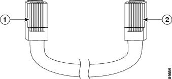
On a crossover cable, the wire connected to the pin on the outside of the left plug should be the same color as the wire connected to the pin on the outside of the right plug.
Update to the Getting Start Guide
When you launch Express Setup, you are prompted for the switch password. Enter the default password, cisco. The switch ignores text in the username field. Before you complete and exit Express Setup, you must change the password from the default password, cisco.
Related Documentation
These documents provide complete information about the switch and are available from this Cisco.com site:
http://www.cisco.com/en/US/products/hw/switches/ps646/tsd_products_support_series_home.html
•
•
•
•
•
•
For information about other related products, see these documents:
•
•
•
•
•
Obtaining Documentation, Obtaining Support, and Security Guidelines
For information on obtaining documentation, obtaining support, providing documentation feedback, security guidelines, and also recommended aliases and general Cisco documents, see the monthly What's New in Cisco Product Documentation, which also lists all new and revised Cisco technical documentation, at:
http://www.cisco.com/en/US/docs/general/whatsnew/whatsnew.html
This document is to be used in conjunction with the documents listed in the "Obtaining Documentation, Obtaining Support, and Security Guidelines" section.
CCDE, CCENT, CCSI, Cisco Eos, Cisco HealthPresence, Cisco IronPort, the Cisco logo, Cisco Nurse Connect, Cisco Pulse, Cisco SensorBase, Cisco StackPower, Cisco StadiumVision, Cisco TelePresence, Cisco Unified Computing System, Cisco WebEx, DCE, Flip Channels, Flip for Good, Flip Mino, Flipshare (Design), Flip Ultra, Flip Video, Flip Video (Design), Instant Broadband, and Welcome to the Human Network are trademarks; Changing the Way We Work, Live, Play, and Learn, Cisco Capital, Cisco Capital (Design), Cisco:Financed (Stylized), Cisco Store, Flip Gift Card, and One Million Acts of Green are service marks; and Access Registrar, Aironet, AllTouch, AsyncOS, Bringing the Meeting To You, Catalyst, CCDA, CCDP, CCIE, CCIP, CCNA, CCNP, CCSP, CCVP, Cisco, the Cisco Certified Internetwork Expert logo, Cisco IOS, Cisco Lumin, Cisco Nexus, Cisco Press, Cisco Systems, Cisco Systems Capital, the Cisco Systems logo, Cisco Unity, Collaboration Without Limitation, Continuum, EtherFast, EtherSwitch, Event Center, Explorer, Follow Me Browsing, GainMaker, iLYNX, IOS, iPhone, IronPort, the IronPort logo, Laser Link, LightStream, Linksys, MeetingPlace, MeetingPlace Chime Sound, MGX, Networkers, Networking Academy, PCNow, PIX, PowerKEY, PowerPanels, PowerTV, PowerTV (Design), PowerVu, Prisma, ProConnect, ROSA, SenderBase, SMARTnet, Spectrum Expert, StackWise, WebEx, and the WebEx logo are registered trademarks of Cisco Systems, Inc. and/or its affiliates in the United States and certain other countries.
All other trademarks mentioned in this document or website are the property of their respective owners. The use of the word partner does not imply a partnership relationship between Cisco and any other company. (0910R)
Any Internet Protocol (IP) addresses used in this document are not intended to be actual addresses. Any examples, command display output, and figures included in the document are shown for illustrative purposes only. Any use of actual IP addresses in illustrative content is unintentional and coincidental.
© 2009 Cisco Systems, Inc. All rights reserved.


 Feedback