Getting Started Guide for Cisco Catalyst 2960-X and 2960-XR Series Switches
Getting Started with Your Switch
This guide provides instructions on how to use Express Setup to initially configure your Catalyst switch. It also covers switch management options, basic rack-mounting, stacking guidelines, port and module connection procedures, and troubleshooting help.
 Note |
Before installing or upgrading the switch, refer to the release notes. |
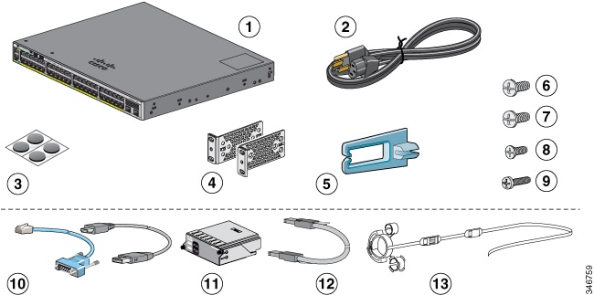
Box Contents
|
1 |
Catalyst 2960-X switch1 or Catalyst 2960-XR switch (power supply modules not shown) |
8 |
Eight number-8 Phillips flat-head screws (48-2927-01) |
|
2 |
AC power cord |
9 |
One black Phillips machine screw (48-0654-01) |
|
3 |
Four rubber mounting feet |
10 |
(Optional)2 Console cable or USB cable |
|
4 |
Two 19-inch mounting brackets |
11 |
(Optional)2 Cisco FlexStack-Plus module 3 |
|
5 |
Cable guide |
12 |
(Optional)2 4Cisco FlexStack cable |
|
6 |
Four number-12 Phillips pan-head screws (48-0523-01) |
13 |
(Optional) 2Power cord retainer (PWR-CLP) |
|
7 |
Four number-10 Phillips pan-head screws (48-0627-01) |
- |
- |
Running Express Setup
Before you begin
When you first set up the switch, you should use Express Setup to enter the initial IP information. This enables the switch to connect to local routers and the network. You can then access the switch through the IP address for further configuration.
Note |
To use the CLI-based initial setup program, see the switch hardware guide on Cisco.com. |
You need this equipment to set up the switch:
-
A PC with Windows Vista, XP, or 2000 installed. Other laptops and browsers might work.
-
A web browser (Internet Explorer 5.5. 6.0, 7.0, Firefox 1.5, 2.0, and 3.0) with JavaScript enabled.
-
A straight-through or crossover Category 5 or 6 Ethernet cable.
Note |
Before running Express Setup, disable any pop-up blockers or proxy settings in your browser software and any wireless client running on your PC. |
SUMMARY STEPS
- Make sure that nothing is connected to the switch.
- During Express Setup, the switch acts as a DHCP server. If your PC has a static IP address, temporarily configure your PC settings to use DHCP before proceeding to the next step.
- Power the switch by connecting the AC power cord to the switch power supply and to a grounded AC outlet.
- Observe the POST results.
- Press the Mode button when the SYST, MAST, and STAT LED turn green, hold the Mode button until all the LEDs next to the Mode button turn green.
- Connect a Category 5 or 6 Ethernet cable to a port:
- Start a browser session on the PC, and enter the IP address https://10.0.0.1. When prompted, enter the default password, cisco.
- Enter this information in the Network Settings fields:
- Enter information in the optional fields.
- Click Submit to save your changes and to complete the initial setup.
- Disconnect the switch from the PC, and install the switch in your network.
- If you changed the static IP address on your PC in Step 2, change it to the previously configured static IP address.
- You can now manage the switch by using Cisco Network Assistant, Device Manager, or both. See Managing the Switch for information about configuring and managing the switch. We strongly recommend that you download Cisco Network Assistant from Cisco.com and use it to manage the switch.
DETAILED STEPS
| Step 1 |
Make sure that nothing is connected to the switch. 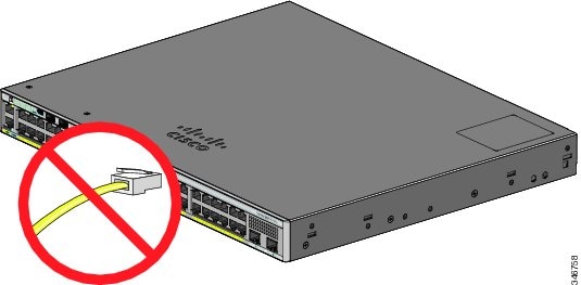 |
||||
| Step 2 |
During Express Setup, the switch acts as a DHCP server. If your PC has a static IP address, temporarily configure your PC settings to use DHCP before proceeding to the next step.
|
||||
| Step 3 |
Power the switch by connecting the AC power cord to the switch power supply and to a grounded AC outlet. For information about installing the power supplies in the Catalyst 2960-XR switches, see the hardware guide at http://www.cisco.com/go/cat2960xr_docs 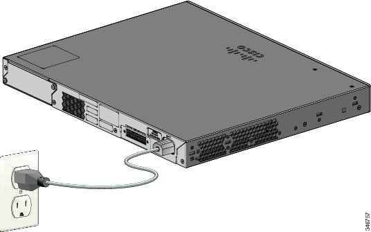 |
||||
| Step 4 |
Observe the POST results. Approximately 30 seconds after the switch powers on, it begins the power-on self-test (POST), which can take up to 5 minutes to complete. During POST, the SYST (system) LED blinks green. When POST is complete, the SYST LED turns solid green. The MAST (master) LED is green if the switch is acting as the stack master. Before going to the next step, wait until POST is complete.
|
||||
| Step 5 |
Press the Mode button when the SYST, MAST, and STAT LED turn green, hold the Mode button until all the LEDs next to the Mode button turn green. You might need to hold the button for more than 3 seconds. The switch is now in Express Setup mode. 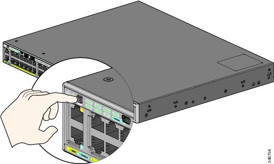
|
||||
| Step 6 |
Connect a Category 5 or 6 Ethernet cable to a port:
Connect the other end of the cable to the Ethernet port on your PC. Wait until the port LEDs on the switch and your PC or laptop are green or blinking green. Green LEDs indicate a successful connection.
|
||||
| Step 7 |
Start a browser session on the PC, and enter the IP address https://10.0.0.1. When prompted, enter the default password, cisco.
The Express Setup window appears. If the Express Setup window does not appear, make sure that any pop-up blockers or proxy settings on your browser are disabled and that any wireless client is disabled on your PC or laptop. |
||||
| Step 8 |
Enter this information in the Network Settings fields:
(Optional) Enter this information in the Ethernet Management Port Settings fields:
|
||||
| Step 9 |
Enter information in the optional fields. You can enter other administrative settings in the Express Setup window. For example, the optional administrative settings identify and synchronize the switch for enhanced management. The switch clock is automatically synchronized with the network clock by using NTP. You can manually set the system clock settings if the switch should have different time settings. |
||||
| Step 10 |
Click Submit to save your changes and to complete the initial setup. After you click Submit:
|
||||
| Step 11 |
Disconnect the switch from the PC, and install the switch in your network. |
||||
| Step 12 |
If you changed the static IP address on your PC in Step 2, change it to the previously configured static IP address. |
||||
| Step 13 |
You can now manage the switch by using Cisco Network Assistant, Device Manager, or both. See Managing the Switch for information about configuring and managing the switch. We strongly recommend that you download Cisco Network Assistant from Cisco.com and use it to manage the switch. You can display Device Manager by following these steps:
|
Managing the Switch
After completing Express Setup and installing the switch in your network, you can use one of these options for further configuration.
Using Device Manager
The simplest way to manage the switch is by using Device Manager in the switch memory. This web interface offers quick configuration and monitoring. You can access Device Manager from anywhere in your network through a web browser.
SUMMARY STEPS
- Launch a web browser on your PC or workstation.
- Enter the switch IP address in the web browser, and press Enter. The Device Manager page appears.
- Use Device Manager to perform basic switch configuration and monitoring. See the Device Manager online help for more information.
- For a more advanced configuration, download and run Cisco Network Assistant, which is described in the next section.
DETAILED STEPS
| Step 1 |
Launch a web browser on your PC or workstation. |
| Step 2 |
Enter the switch IP address in the web browser, and press Enter. The Device Manager page appears. |
| Step 3 |
Use Device Manager to perform basic switch configuration and monitoring. See the Device Manager online help for more information. |
| Step 4 |
For a more advanced configuration, download and run Cisco Network Assistant, which is described in the next section. |
Using Cisco Network Assistant
Cisco Network Assistant is a software program that you download from Cisco.com and run on your PC. It offers advanced options for configuring and monitoring multiple devices, including switches, switch clusters, switch stacks, routers, and access points. Cisco Network Assistant is free—there is no charge to download, install, or use it.
Go to this URL: http://www.cisco.com/en/US/products/ps5931/index.html
SUMMARY STEPS
- Click the Download Software link, and select the version that you want to download.
- Find the Network Assistant installer.
- Download the Network Assistant installer and run it. (You can run it directly from the Web if your browser offers this choice.)
- When you run the installer, follow the displayed instructions. In the final panel, click Finish to complete the Network Assistant installation.
DETAILED STEPS
| Step 1 |
Click the Download Software link, and select the version that you want to download. You must be a registered Cisco.com user, but you need no other access privileges. |
| Step 2 |
Find the Network Assistant installer. |
| Step 3 |
Download the Network Assistant installer and run it. (You can run it directly from the Web if your browser offers this choice.) |
| Step 4 |
When you run the installer, follow the displayed instructions. In the final panel, click Finish to complete the Network Assistant installation. See the Network Assistant online help and the getting started guide for more information. |
Using the Command-Line Interface
You can enter Cisco IOS commands and parameters through the CLI. Access the CLI by using one of these options.
RJ-45 Console Port
SUMMARY STEPS
- Connect the supplied RJ-45-to-DB-9 adapter cable to the standard 9-pin serial port on the PC. Connect the other end of the cable to the console port on the switch.
- Start a terminal-emulation program on the PC.
- Configure the PC terminal emulation software for 9600 baud, 8 data bits, no parity, 1 stop bit, and no flow control.
- Use the CLI to enter commands to configure the switch.
DETAILED STEPS
| Step 1 |
Connect the supplied RJ-45-to-DB-9 adapter cable to the standard 9-pin serial port on the PC. Connect the other end of the cable to the console port on the switch. |
| Step 2 |
Start a terminal-emulation program on the PC. |
| Step 3 |
Configure the PC terminal emulation software for 9600 baud, 8 data bits, no parity, 1 stop bit, and no flow control. |
| Step 4 |
Use the CLI to enter commands to configure the switch. |
Switch Ethernet Management Port
SUMMARY STEPS
- Connect a Category 5 Ethernet cable to the PC Ethernet port. Connect the other end of the cable to the Ethernet management port on the switch.
- Start a Telnet session on the PC.
- Enter the switch IP address that you assigned by using Express Setup.
- Use the CLI to enter commands to configure the switch.
DETAILED STEPS
| Step 1 |
Connect a Category 5 Ethernet cable to the PC Ethernet port. Connect the other end of the cable to the Ethernet management port on the switch. |
| Step 2 |
Start a Telnet session on the PC. |
| Step 3 |
Enter the switch IP address that you assigned by using Express Setup. |
| Step 4 |
Use the CLI to enter commands to configure the switch. |
Switch USB Mini-Type B Console Port
SUMMARY STEPS
- Connect an USB cable to the PC USB port. Connect the other end of the cable to the mini B (5-pin-connector) USB port on the switch.
- Start a terminal-emulation program on the PC.
- Configure the PC terminal emulation software for 9600 baud, 8 data bits, no parity, 1 stop bit, and no flow control.
- Use the CLI to enter commands to configure the switch. See the software configuration guide and the command reference for more information.
DETAILED STEPS
| Step 1 |
Connect an USB cable to the PC USB port. Connect the other end of the cable to the mini B (5-pin-connector) USB port on the switch. |
||
| Step 2 |
Start a terminal-emulation program on the PC. |
||
| Step 3 |
Configure the PC terminal emulation software for 9600 baud, 8 data bits, no parity, 1 stop bit, and no flow control. |
||
| Step 4 |
Use the CLI to enter commands to configure the switch. See the software configuration guide and the command reference for more information.
|
Using Other Management Options
Cisco Prime Infrastructure combines the wireless functionality of Cisco Prime Network Control System (NCS) and the wired functionality of Cisco Prime LAN Management Solution (LMS) with application performance monitoring and troubleshooting capabilities of Cisco Prime Assurance Manager. For more information, see the Cisco Prime Infrastructure documentation on Cisco.com.
Planning and Installing a Switch Stack (Optional)
Note |
This section applies only to the Catalyst 2960-X and 2960-XR stacking-capable switches. |
Stack Guidelines
-
Connect only Catalyst 2960-X or 2960-S switches in a mixed switch stack.
Note
You can only create mixed stacks with Catalyst 2960-X or 2960-S switches (up to four switches). You cannot create mixed stacks with other switches. Catalyst 2960-XR switches cannot be added to mixed stacks. They can only stack with other Catalyst 2960-XR switches.
-
Perform one of the following:
-
Install the FlexStack-Plus module and the FlexStack cable.
-
Install the FlexStack-Extended Fiber module and the fiber-optic cable.
-
Install the FlexStack-Extended Hybrid module and the required fiber-optic/FlexStack cables.
Note
All the FlexStack modules are hot-swappable and can be inserted while the switch is powered on.
-
-
Order the appropriate cable from your Cisco sales representative. The length of FlexStack cable depends on your configuration. These are the different sizes available:
-
CAB-STK-E-0.5M= (0.5-meter cable)
-
CAB-STK-E-1M= (1-meter cable)
-
CAB-STK-E-3M= (3-meter cable)
-
-
Make sure that you have access to the switch rear panel and to the rear of the rack.
Installing a FlexStack-Plus or a FlexStack-Extended Module
Note |
The switch should always have a blank module installed when a FlexStack module is not used. |
The Catalyst 2960X-48P-L switch is shown as an example. You can install the module in other switches as shown.
SUMMARY STEPS
- Use a number 2 Phillips-head screwdriver to remove the FlexStack module blank cover on the switch back panel.
- Grasp the FlexStack module on the sides, and insert it into the module slot. Push the module in completely until you feel it snap into place.
- Secure the screws on each side of the module.
DETAILED STEPS
| Step 1 |
Use a number 2 Phillips-head screwdriver to remove the FlexStack module blank cover on the switch back panel. 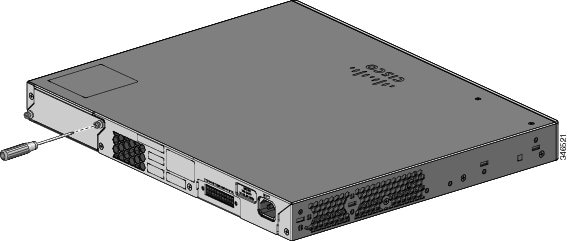 |
||
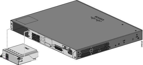
| Step 2 |
Grasp the FlexStack module on the sides, and insert it into the module slot. Push the module in completely until you feel it snap into place. The following example image uses FlexStack-Plus module.
 |
||
| Step 3 |
Secure the screws on each side of the module. 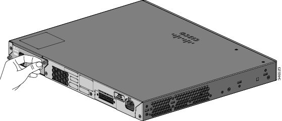
|
Stack Cabling
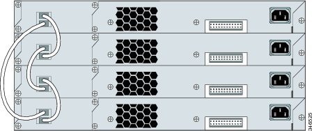
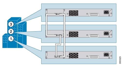
Stacking using FlexStack-Plus Modules
Stacking using FlexStack-Extended Modules
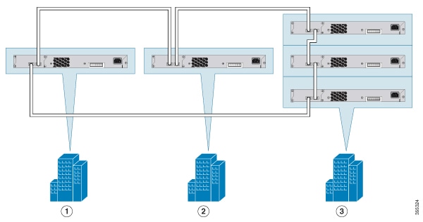
This section explains the supported stacking topologies using FlexStack-Extended Modules.
The following topology is created by stacking switches with FlexStack-Extended Fiber modules that are deployed across different floors of a building. The SFP+ module ports are connected using fiber cables.
The following topology is created by stacking switches with FlexStack-Extended Fiber modules that are deployed across multiple buildings of a campus and different floors of a building.
Using FlexStack-Extended Hybrid module, you can combine existing stack of switches and new switches spread across multiple wiring closets into one single stack. To achieve this, the copper port on the FlexStack-Extended Hybrid module should be connected to the FlexStack-Plus port on a switch in your existing network. The fiber port on the Cisco FlexStack-Extended Fiber module can be used to connect switches over long distances. You can stack up to eight switches.
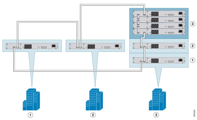
The following image shows a mixed stack network using FlexStack-Plus, FlexStack-Extended Fiber and Hybrid modules. This is one of the supported topologies using FlexStack modules. Typically, fiber modules are used to extend a network for long distance communication across buildings or floors in a building.
Installing the Switch
This section describes rack-mounting using 19-inch and 23-inch rack-mounting brackets. For optional bracket information and alternate mounting procedures, such as installing the switch in a 24-inch rack or on a wall, and for additional cabling information, see the Hardware Installation Guide on Cisco.com.
Tools and Equipment
Obtain these necessary tools:
-
A Number-2 Phillips screwdriver to rack-mount the switch
Installation Guidelines
When determining where to install the switch, verify that these guidelines are met:
-
Clearance to the switch front and rear panel meets these conditions:
-
Front-panel LEDs can be easily read.
-
Access to ports is sufficient for unrestricted cabling.
-
AC power cord can reach from the AC power outlet to the connector on the switch rear panel.
-
-
Cabling is away from sources of electrical noise, such as radios, power lines, and fluorescent lighting fixtures. Make sure that the cabling is safely away from other devices that might damage the cables.
-
For switches with the optional 1025-W power-supply module, first rack-mount the switch before installing the power-supply module.
-
Make sure power-supply modules are securely inserted in the chassis before moving the switch.
-
When connecting or disconnecting the power cord on a switch that is installed above or below a 1025-W power supply-equipped switch, you might need to remove the module from the switch to access the power cord.
-
Airflow around the switch and through the vents is unrestricted.
- For the Catalyst
2960X-24PSQ-L switches: Allow these clearances:
-
Top and bottom: 1.75 in. (44.44 mm)
-
Back of switch: 3 in. (76.19 mm)
-
-
Temperature around the unit does not exceed 113°F (45°C). If the switch is installed in a closed or multirack assembly, the temperature around it might be greater than normal room temperature.
-
Humidity around the switch does not exceed 95 percent.
-
Altitude at the installation site is not greater than 10,000 feet.
-
For 10/100/1000 fixed ports, the cable length from a switch to a connected device cannot exceed 328 feet (100 meters).
-
Cooling mechanisms, such as fans and blowers in the switch, can draw dust and other particles causing contaminant buildup inside the chassis, which can result in system malfunction. You must install this equipment in an environment as free from dust and foreign conductive material (such as metal flakes from construction activities) as is possible.
Installation Warning Statements
This document includes the basic installation warning statements. Translations of these warning statements appear in the switch compliance and safety information guide document on Cisco.com.
 Warning |
To prevent bodily injury when mounting or servicing this unit in a rack, you must take special precautions to ensure that the system remains stable. The following guidelines are provided to ensure your safety: - This unit should be mounted at the bottom of the rack if it is the only unit in the rack. - When mounting this unit in a partially filled rack, load the rack from the bottom to the top with the heaviest component at the bottom of the rack. - If the rack is provided with stabilizing devices, install the stabilizers before mounting or servicing the unit in the rack. Statement 1006 |
Warning |
Class 1 laser product. Statement 1008 |
Warning |
This equipment must be grounded. Never defeat the ground conductor or operate the equipment in the absence of a suitably installed ground conductor. Contact the appropriate electrical inspection authority or an electrician if you are uncertain that suitable grounding is available. Statement 1024 |
Warning |
To prevent the system from overheating, do not operate it in an area that exceeds the maximum recommended ambient temperature of: 113°F (45°C). Statement 1047 |
Warning |
To prevent airflow restriction, allow clearance around the ventilation openings to be at least: 3 inches (7.6 cm). Statement 1076 |
Attaching the Rack-Mount Brackets for the Catalyst 2960-X Switches
SUMMARY STEPS
- Use two Phillips flat-head screws to attach the long side of the bracket to each side of the switch.
DETAILED STEPS
|
Use two Phillips flat-head screws to attach the long side of the bracket to each side of the switch. 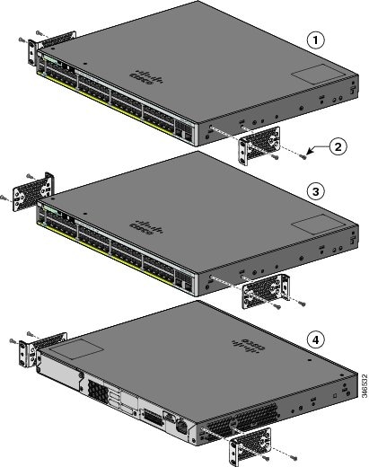
|
Attaching the Rack-Mount Brackets for the Catalyst 2960-XR Switches
SUMMARY STEPS
- Use four Phillips flat-head screws to attach the long side of the bracket to each side of the switch.
DETAILED STEPS
|
Use four Phillips flat-head screws to attach the long side of the bracket to each side of the switch. 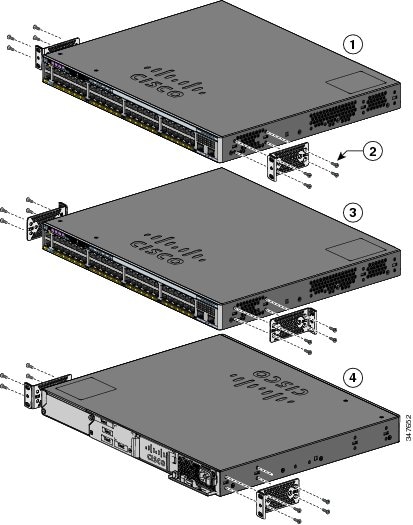
|
Mounting in a Rack
SUMMARY STEPS
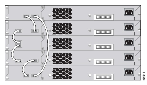
- Use the four supplied Phillips machine screws to attach the brackets to the rack.
- Use the black Phillips machine screw to attach the cable guide to the left or right bracket.
DETAILED STEPS
| Step 1 |
Use the four supplied Phillips machine screws to attach the brackets to the rack. |
||||||||||||
| Step 2 |
Use the black Phillips machine screw to attach the cable guide to the left or right bracket. 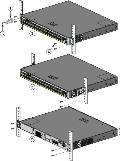
|
Connecting FlexStack-Plus modules (Optional)
Always use a Cisco-approved FlexStack cable to connect the switches.
Note |
This is only supported on the stack-capable switches. |
 Caution |
Use only approved cables, and connect only to other Catalyst 2960-X or 2960-S switches. Equipment might be damaged if connected to other nonapproved Cisco cables or equipment. |
SUMMARY STEPS
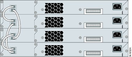
- Remove the dust covers from the FlexStack cables, and store them for future use.
- Insert one end of the FlexStack cable into the stack port of the first switch. Insert the other end of the cable into the stack port on the other switch. Make sure that you insert the cables in completely until you feel them snap into place.
- Replace the dust covers when you remove the FlexStack cables from the connectors.
DETAILED STEPS
| Step 1 |
Remove the dust covers from the FlexStack cables, and store them for future use. |
||
| Step 2 |
Insert one end of the FlexStack cable into the stack port of the first switch. Insert the other end of the cable into the stack port on the other switch. Make sure that you insert the cables in completely until you feel them snap into place. 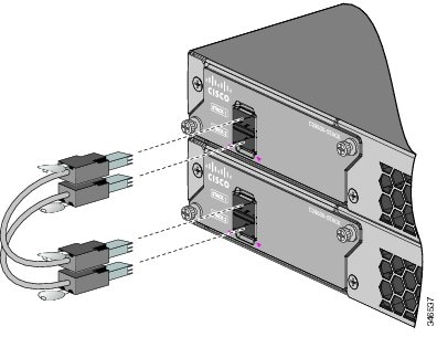
|
||
| Step 3 |
Replace the dust covers when you remove the FlexStack cables from the connectors.
|
Connecting to the Switch Ports
This section describes how to connect to the fixed switch ports and to the Small Form-Factor Pluggable (SFP) module ports.
Connecting to the 10/100/100 or 10/100/1000 PoE+ Ports
The fixed ports on the Cisco Catalyst 2960-Xor Cisco Catalyst 2960-XR Power over Ethernet Plus (PoE+) switches provide:
-
PoE+ support for IEEE 802.3at-compliant powered devices
-
PoE support for IEEE 802.3af-compliant powered devices
-
Support for Cisco enhanced PoE (ePoE)
These ports also provide Cisco prestandard PoE support for Cisco IP phones and Cisco Aironet Access Points. See the Cisco Catalyst 2960-X or Cisco Catalyst 2960-XR Hardware Installation Guide for information on PoE budgeting. By default, a switch PoE port automatically provides power when a compliant device is connected, including ePoE, PoE, and PoE+.
Note |
The automatic medium-dependent interface crossover (auto-MDIX) feature is enabled by default. The switch detects the required cable type for copper Ethernet connections and configures the interfaces accordingly. Therefore, you can use either a crossover or a straight-through cable for connections to a copper 10/100/1000 module port on the switch, regardless of the type of device at the other end of the connection. |
SUMMARY STEPS
- Insert a straight-through, twisted four-pair, Category 5 cable in a switch's 10/100/1000 port when you connect to servers, workstations, IP phones, wireless access points, and routers. Use a crossover, twisted four-pair, Category 5 cable when you connect to other switches, hubs, or repeaters.
- Insert the other cable end into an RJ-45 port on the other device.
DETAILED STEPS
| Step 1 |
Insert a straight-through, twisted four-pair, Category 5 cable in a switch's 10/100/1000 port when you connect to servers, workstations, IP phones, wireless access points, and routers. Use a crossover, twisted four-pair, Category 5 cable when you connect to other switches, hubs, or repeaters. |
| Step 2 |
Insert the other cable end into an RJ-45 port on the other device. |
Connecting to SFP and SFP+ Module Slots
Some switch models have SFP module slots and others have SFP+ module slots. The SFP slots support only the SFP modules. The SFP+ slots support both SFP and SFP+ modules. For a list of supported modules, see the Cisco Catalyst 2960-X or Cisco Catalyst 2960-XR Release Notes on Cisco.com. For detailed instructions on installing, removing, and connecting to SFP modules, see the documentation that came with the SFP module.
Caution |
Removing and installing an SFP module can shorten its useful life. Do not remove and insert SFP modules more often than is absolutely necessary. |
SUMMARY STEPS
- Grasp the module on the sides, and insert it into the switch slot until you feel the connector snapping into place.
- Insert an appropriate cable into the module port. Insert the other cable end into the other device.
DETAILED STEPS
| Step 1 |
Grasp the module on the sides, and insert it into the switch slot until you feel the connector snapping into place. 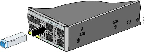 |
| Step 2 |
Insert an appropriate cable into the module port. Insert the other cable end into the other device. |
Verifying Port Connectivity
After you connect the switch port and another device, the port LED turns amber while the switch establishes a link. This process takes about 30 seconds, and then the LED turns green. If the LED turns off, the target device might not be turned on, there might be a cable problem, or there might be a problem with the adapter installed in the target device.
Troubleshooting
If you experience a difficulty, help is available in this section and also on Cisco.com. This section includes Express Setup troubleshooting information, details about how to reset the password, and where to find additional information.
Resetting the Switch
Follow these steps to reset your switch. These are reasons why you might want to reset the switch:
-
You installed the switch in your network and cannot connect to it because you assigned the wrong IP address.
-
You want to reset the password on the switch.
Note
Resetting the switch reboots the switch.
To reset the switch:
-
Press and hold the Mode button. The switch LEDs begin blinking after about 3 seconds.
-
Continue holding down the Mode button. The LEDs stop blinking after 7 more seconds, and then the switch reboots.
The switch now operates like an unconfigured switch. You can enter the switch IP information by using Express Setup.
Accessing Help Online
We recommend that you first look for a solution to your problem in the troubleshooting section of the Hardware Installation Guide on Cisco.com. You can also access the Cisco Technical Support and Documentation website for a list of known hardware problems and extensive troubleshooting documentation.
Troubleshooting Express Setup
|
Did you verify that POST ran successfully before starting Express Setup? |
If not, make sure that only the SYST and STAT LEDs are green before you press the Mode button to enter the Express Setup mode. POST errors are usually fatal. Contact your Cisco technical support representative if your switch fails POST. |
||
|
Did you press the Mode button while the switch was still running POST? |
If yes, wait until POST completes. Power cycle the switch. Wait until POST completes. Confirm that the SYST and STAT LEDs are green. Press the Mode button to enter Express Setup mode. |
||
|
Did you try to continue without confirming that the switch was in Express Setup mode? |
Verify that all LEDs above the Mode button are green. (The RPS LED is off.) If necessary, press the Mode button to enter Express Setup mode. |
||
|
Does your PC have a static IP address? |
If yes, before connecting to the switch, change your PC settings to temporarily use DHCP. |
||
|
Did you connect a crossover cable instead of a straight-through Ethernet cable between a switch port and the Ethernet port of the PC? |
If yes, connect a straight-through cable to an Ethernet port on the switch and the PC. Wait 30 seconds before you enter 10.0.0.1 in the browser. |
||
|
Did you connect the Ethernet cable to the console port instead of to a 10/100/1000 Ethernet port on the switch? |
If yes, disconnect the cable from the console port. Then connect the cable to an Ethernet port on the switch and the PC. Wait
30 seconds before you enter 10.0.0.1 in the browser.
|
||
|
Did you wait 30 seconds after you connected the switch and the PC before you entered the IP address in your browser? |
If not, wait 30 seconds, reenter 10.0.0.1 in the browser, and press Enter. |
||
|
Did you enter the wrong address in the browser, or is there an error message? |
If yes, reenter 10.0.0.1 in the browser, and press Enter. |
Related Documentation
For additional installation and configuration information relating to the switch, see the Cisco Catalyst 2960-XCisco Catalyst 2960-XR documentation on Cisco.com. For system requirements, important notes, limitations, open and resolved bugs, and last-minute documentation updates, see the release notes, also on Cisco.com. For translations of the warnings that appear in this publication, see the switch RCSI guide on Cisco.com.
When using the online publications, see the documents that match the Cisco IOS software version running on the switch. The software version is on the Cisco IOS label on the switch's rear panel.
-
Cisco Catalyst 2960-X switch, located at:
http://www.cisco.com/go/cat2960x_docs -
Catalyst 2960-XR switch, located at:
-
Cisco SFP and SFP+ modules documentation, including compatibility matrixes, located at:
http://www.cisco.com/en/US/products/hw/modules/ps5455/tsd_products_support_series_home.html
 Feedback