Getting Started with the Switch
Getting Started with the Switch
About the document
This guide provides instructions for the initial set up of your Cisco Catalyst 2960-L switch. It includes basic rack-mounting, desk and shelf mounting for the switch, port and module connection procedures, and troubleshooting information.
 Note |
Before installing or upgrading the switch, refer to the Cisco Catalyst 2960-L switch Release Notes available on cisco.com. |
Box Contents
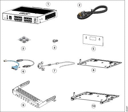
This section lists the contents of the shipping box for an 8-port and 16-port Cisco Catalyst 2960-L switch.
|
1 |
8-port or 16-port Cisco Catalyst 2960-L switch |
6 |
(Optional) Console cable or USB cable |
|
2 |
AC power cord |
7 |
(Optional) Power cord retainer |
|
3 |
Four rubber mounting feet (51-0089) |
8 |
(Optional) Magnet tray combo |
|
4 |
Three number-8 screws (48-1689-01) |
9 |
(Optional) Cable guard |
|
5 |
Screw template (47-100996-02) |
10 |
(Optional) DIN rail mount |
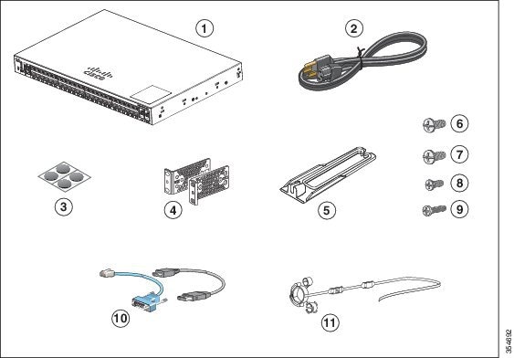
This section lists the contents of the shipping box for a 24-port and 48-port Cisco Catalyst 2960-L switch.
|
1 |
24-port and 48-port Cisco Catalyst 2960-L switch |
7 |
Four Number-10 Phillips pan-head screws (48-0627-01) |
|
2 |
AC power cord |
8 |
Eight Number-8 Phillips flat-head screws (48-2927-01) |
|
3 |
Four rubber-mounting feet (51-0089) |
9 |
One black Phillips machine screw (48-0654-01) |
|
4 |
Two 19-inch mounting brackets |
10 |
(Optional) Console cable or USB cable |
|
5 |
Cable guide |
11 |
(Optional) Power cord retainer |
|
6 |
Four Number-12 Phillips pan-head screws (48-0523-01) |
- |
- |
Installing the Switch
This section describes rack-mounting using 19-inch and 23-inch rack-mounting brackets. For optional bracket information and alternate mounting procedures, such as installing the switch in a 24-inch rack or on a wall, and for additional cabling information, see the Hardware Installation Guide on Cisco.com.
Tools and Equipment
Obtain these necessary tools:
-
A Number-2 Phillips screwdriver.
-
Drill with #27 drill bit (0.144-inch [3.7 mm]) for mounting an 8-port and 16-port switch.
Installation Guidelines
When determining where to install the switch, verify that these guidelines are met:
-
Clearance to the switch's front and rear panel should meet these conditions:
-
Front-panel LEDs can be easily read.
-
Access to ports is sufficient for unrestricted cabling.
-
AC power cord can reach from the AC power outlet to the connector on the switch's rear panel.
-
-
Cabling is away from sources of electrical noise, such as radios, power lines, and fluorescent lighting fixtures. Make sure that the cabling is safely away from other devices that might damage the cables.
-
Airflow around the switch and through the vents is unrestricted. To avoid any flow blockage, we strongly recommend these guidelines:
-
Allow at least 3 in. (7.6 cm) of clearance from the left and the right sides, and the front and rear of the switch.
-
Allow at least 1.75 in. (4 cm) of clearance from the top cover, if you are installing the switch in upright position.
-
Allow at least 3 in. (7.6 cm) of clearance from the top cover, if you are installing the switch inverted, under a table.
-
Allow at least 1 RU of empty rack space above the switch, if you are installing the switch in a rack.
-
-
Temperature around the unit does not exceed 113°F (45°C). If the switch is installed in a closed or multirack assembly, the temperature around it might be greater than normal room temperature.
-
Humidity around the switch does not exceed 95 percent.
-
Altitude at the installation site is not greater than 10,000 feet.
-
For 10/100/1000 fixed ports, the cable length from a switch to a connected device cannot exceed 328 feet (100 meters).
-
Cooling mechanisms, such as fans and blowers in the switch, can draw dust and other particles causing contaminant build-up inside the chassis, which can result in system malfunction. You must install this equipment in an environment as free from dust and foreign conductive material (such as metal flakes from construction activities) as is possible.
-
None of the switch models can be deployed outside of the wiring closet. These switches can only be deployed indoors.
Safety Warnings
This section includes the warning statements relating to basic installation. Read this section before you start the installation procedure.
 Warning |
Before working on equipment that is connected to power lines, remove jewelry (including rings, necklaces, and watches). Metal objects will heat up when connected to power and ground and can cause serious burns or weld the metal object to the terminals. Statement 43 |
Warning |
Do not stack the chassis on any other equipment. If the chassis falls, it can cause severe bodily injury and equipment damage. Statement 48 |
Warning |
Read the wall-mounting instructions carefully before beginning installation. Failure to use the correct hardware or to follow the correct procedures could result in a hazardous situation to people and damage to the system. Statement 378 |
Warning |
Do not work on the system or connect or disconnect cables during periods of lightning activity. Statement 1001 |
Warning |
Read the installation instructions before connecting the system to the power source. Statement 1004 |
Warning |
To prevent bodily
injury when mounting or servicing this unit in a rack, you must take special
precautions to ensure that the system remains stable. The following guidelines
are provided to ensure your safety:
|
Warning |
Class 1 laser product. Statement 1008 |
Warning |
Do not stare into the laser beam. Statement 1010 |
Warning |
This unit is intended for installation in restricted access areas. A restricted access area can be accessed only through the use of a special tool, lock and key, or other means of security. Statement 1017 |
Warning |
The plug-socket combination must be accessible at all times, because it serves as the main disconnecting device. Statement 1019 |
Warning |
To avoid electric shock, do not connect safety extra-low voltage (SELV) circuits to telephone-network voltage (TNV) circuits. LAN ports contain SELV circuits, and WAN ports contain TNV circuits. Some LAN and WAN ports both use RJ-45 connectors. Use caution when connecting cables. Statement 1021 |
Warning |
A readily accessible two-poled disconnect device must be incorporated in the fixed wiring. Statement 1022 |
Warning |
This equipment must be grounded. Never defeat the ground conductor or operate the equipment in the absence of a suitably installed ground conductor. Contact the appropriate electrical inspection authority or an electrician if you are uncertain that suitable grounding is available. Statement 1024 |
Warning |
Only trained and qualified personnel should be allowed to install, replace, or service this equipment. Statement 1030 |
Warning |
Ultimate disposal of this product should be handled according to all national laws and regulations. Statement 1040 |
Warning |
When installing or replacing the unit, the ground connection must always be made first and disconnected last. Statement 1046 |
Warning |
To prevent the system from overheating, do not operate it in an area that exceeds the maximum recommended ambient temperature of: <113°F (45°C). Statement 1047 |
Note |
The maximum operating temperature is 40°C for Catalyst WS-C2960L-16PS-LL switches and 45°C for all the other switch models. |
Warning |
Invisible laser radiation may be emitted from disconnected fibers or connectors. Do not stare into beams or view directly with optical instruments. Statement 1051 |
Warning |
This warning symbol means danger. You are in a situation that could cause bodily injury. Before you work on any equipment, be aware of the hazards involved with electrical circuitry and be familiar with standard practices for preventing accidents. Use the statement number provided at the end of each warning to locate its translation in the translated safety warnings that accompanied this device. Statement 1071 |
Warning |
Voltages that present a shock hazard may exist on Power over Ethernet (PoE) circuits if interconnections are made using uninsulated exposed metal contacts, conductors, or terminals. Avoid using such interconnection methods, unless the exposed metal parts are located within a restricted access location and users and service people who are authorized within the restricted access location are made aware of the hazard. A restricted access area can be accessed only through the use of a special tool, lock and key or other means of security. Statement 1072 |
Warning |
No user-serviceable parts inside. Do not open. Statement 1073 |
Warning |
Installation of the equipment must comply with local and national electrical codes. Statement 1074 |
Warning |
To prevent airflow restriction, allow clearance around the ventilation openings to be at least: 3 inches (7.6 cm). Statement 1076 |
Warning |
Hot surface. Statement 1079 |
Desk-Mounting or Shelf-Mounting the Switch
Mounting on a Desk or Shelf Without Mounting Screws
Procedure
| Step 1 |
Locate the adhesive strip with the rubber feet in the accessory kit. |
||
| Step 2 |
Remove the four rubber feet from the adhesive strip, and attach them to the recessed areas at the bottom of the unit. This prevents the switch from sliding on the desk or shelf.
|
||
| Step 3 |
Place the switch on the desk or shelf. |
Mounting on a Desk or Shelf with Mounting Screws
Note |
This procedure is applicable only for 8-port and 16-port switch models. |
Procedure
| Step 1 |
Use the screw template to align the mounting screw holes and also as a guide to make sure that you install the screws into the desk or shelf with proper clearance. |
||||||||
| Step 2 |
Position the screw template on top of the desk or shelf so that the edge that is marked as CABLE SIDE ENTRY faces the front of the desk or shelf. This ensures that the power cord faces the rear of the desk or shelf after the switch is installed. |
||||||||
| Step 3 |
Peel the adhesive strip off the bottom of the screw template and attach it to the top of the desk or shelf. |
||||||||
| Step 4 |
Use a 0.144-inch (3.7 mm) or a #27 drill bit to drill a 1/2-inch (12.7 mm) hole in the two screw template slots. |
||||||||
| Step 5 |
Insert two screws into the slots on the screw template, and tighten them until they touch the top of the screw template. 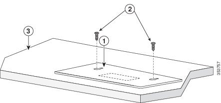
|
||||||||
| Step 6 |
Remove the screw template from the desk or shelf. |
||||||||
| Step 7 |
Place the switch on the mounting screws, and slide it forward until it locks in place. 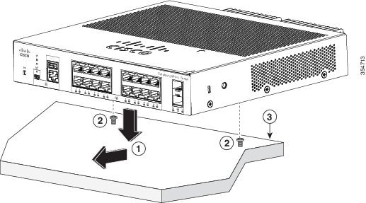
|
Rack-Mounting the Switch
Attaching the Rack-Mount Brackets
Attaching the Rack-Mount Brackets to an 8-Port and 16-Port Cisco Catalyst 2960-L Switch
Installing an 8-port and 16-port Cisco Catalyst 2960-L switch in a 19-inch rack requires an optional bracket kit that is not included with the switch. You can order these kits by contacting your Cisco representative.
Use the Phillips flat-head screws that are available with the bracket kit to attach the brackets to the switch.
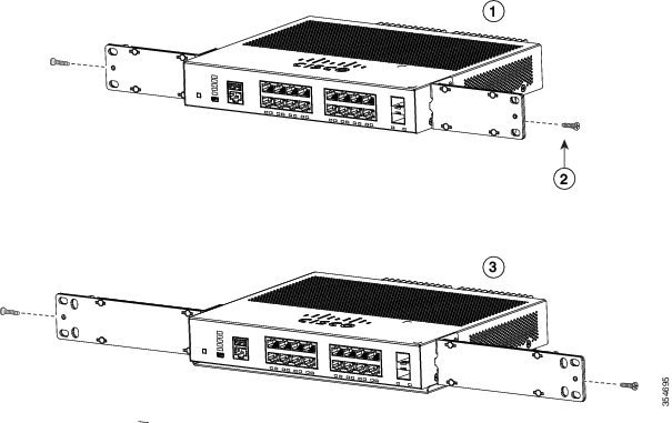
|
1 |
Switch with 19-inch brackets attached |
3 |
Switch with 23-inch brackets attached |
|
2 |
Number-8 Phillips flat-head screws |
Attaching the Rack-Mount Brackets to a 24-Port and 48-Port Cisco Catalyst 2960-L Switch
Use two Phillips flat-head screws to attach the long side of the bracket to each side of the switch.
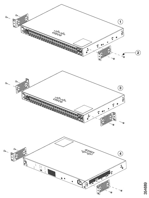
|
1 |
Front-mounting position |
3 |
Mid-mounting position |
|
2 |
Number-8 Phillips flat-head screws |
4 |
Rear-mounting position |
Mounting an 8-Port or 16-Port Switch in a Rack
Procedure
| Step 1 |
Use the four Number-12 or Number-10 Phillips machine screws to attach the brackets to the rack. |
||||||||
| Step 2 |
Use the black Phillips machine screw to attach the cable guide to the left or right bracket. 
|
Mounting a 24-Port or 48-Port Switch in a Rack
Procedure
| Step 1 |
Use the four supplied Phillips machine screws to attach the brackets to the rack. |
||||||||||||
| Step 2 |
Use the black Phillips machine screw to attach the cable guide to the left or right bracket. 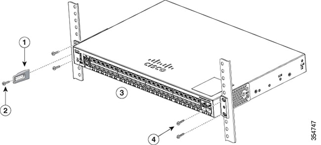 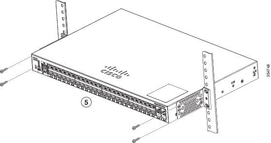 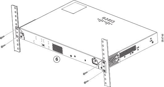
|
Connecting to the Switch Ports
This section describes how to connect to the fixed switch ports and to the Small Form-Factor Pluggable (SFP) module ports.
Connecting to the 10/100/100 or 10/100/1000 PoE+ Ports
The fixed ports on the Cisco Catalyst 2960-L Power over Ethernet Plus (PoE+) switches provide:
-
PoE+ support for IEEE 802.3at-compliant powered devices
-
PoE support for IEEE 802.3af-compliant powered devices
These ports also provide Cisco prestandard PoE support for Cisco IP phones and Cisco Aironet Access Points. See the Cisco Catalyst 2960-L Hardware Installation Guide for information on PoE budgeting. By default, a switch PoE port automatically provides power when a compliant device is connected, including PoE, and PoE+.
Note |
The automatic medium-dependent interface crossover (auto-MDIX) feature is enabled by default. The switch detects the required cable type for copper Ethernet connections and configures the interfaces accordingly. Therefore, you can use either a crossover or a straight-through cable for connections to a copper 10/100/1000 module port on the switch, regardless of the type of device at the other end of the connection. |
SUMMARY STEPS
- Insert a straight-through, twisted four-pair, Category 5 cable in a switch's 10/100/1000 port when you connect to servers, workstations, IP phones, wireless access points, and routers. Use a crossover, twisted four-pair, Category 5 cable when you connect to other switches, hubs, or repeaters.
- Insert the other cable end into an RJ-45 port on the other device.
DETAILED STEPS
| Step 1 |
Insert a straight-through, twisted four-pair, Category 5 cable in a switch's 10/100/1000 port when you connect to servers, workstations, IP phones, wireless access points, and routers. Use a crossover, twisted four-pair, Category 5 cable when you connect to other switches, hubs, or repeaters. |
| Step 2 |
Insert the other cable end into an RJ-45 port on the other device. |
Connecting to SFP Module Slots
For a list of supported modules, see the Cisco Catalyst 2960-L Release Notes on Cisco.com. For detailed instructions on installing, removing, and connecting to SFP modules, see the documentation that came with the SFP module.
 Caution |
Removing and installing an SFP module can shorten its useful life. Do not remove and insert SFP modules more often than is absolutely necessary. |
SUMMARY STEPS
- Grasp the module on the sides, and insert it into the switch slot until you feel the connector snapping into place.
- Insert an appropriate cable into the module port. Insert the other cable end into the other device.
DETAILED STEPS
| Step 1 |
Grasp the module on the sides, and insert it into the switch slot until you feel the connector snapping into place. 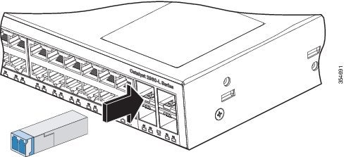 |
| Step 2 |
Insert an appropriate cable into the module port. Insert the other cable end into the other device. |
Verifying Port Connectivity
After you connect the switch port and another device, the port LED turns amber while the switch establishes a link. This process takes about 30 seconds, and then the LED turns green. If the LED turns off, the target device might not be turned on, there might be a cable problem, or there might be a problem with the adapter installed in the target device.
Troubleshooting
If you experience a difficulty, help is available in this section and also on Cisco.com. This section includes Express Setup troubleshooting information, details about how to reset the password, and where to find additional information.
Resetting the Switch Password
Follow these steps to reset the password on a Cisco Catalyst 2960-L switch:
Procedure
| Step 1 |
Unplug the power cord. |
||
| Step 2 |
Reconnect the power cord to the switch, then press and hold the Mode button for three to four seconds and release it. The switch power-cycles and displays the switch: prompt.
|
||
| Step 3 |
Run the dir flash: command. The
switch file system is displayed.
|
||
| Step 4 |
Enter rename flash:config.text flash:config.old to rename the configuration file. |
||
| Step 5 |
Run the boot command to boot the system. |
||
| Step 6 |
Enter n at the prompt and press Enter to abort the initial configuration dialog box. |
||
| Step 7 |
In the switch prompt, type en to enter the enable mode. |
||
| Step 8 |
Enter rename flash:config.old flash:config.text to rename the configuration file with its original name. |
||
| Step 9 |
Run the copy command to copy the configuration file into memory. The
configuration file reloads.
|
||
| Step 10 |
Overwrite the current passwords and enter a strong password with atleast one capital letter, one number, and one special character.
|
||
| Step 11 |
Enter the write memory command to write the running configuration to the configuration file. |
Accessing Help Online
We recommend that you first look for a solution to your problem in the troubleshooting section of the Hardware Installation Guide on Cisco.com. You can also access the Cisco Technical Support and Documentation website for a list of known hardware problems and extensive troubleshooting documentation.
Related Documentation
For additional installation and configuration information relating to the switch, see the Cisco Catalyst 2960-L documentation on Cisco.com. For system requirements, important notes, limitations, open and resolved bugs, and last-minute documentation updates, see the release notes, also on Cisco.com. For translations of the warnings that appear in this publication, see the switch RCSI guide on Cisco.com.
When using the online publications, see the documents that match the Cisco IOS software version running on the switch. The software version is on the Cisco IOS label on the switch's rear panel.
-
Cisco Catalyst 2960-L switch, located at:
-
Cisco SFP modules documentation, including compatibility matrixes, located at:
http://www.cisco.com/en/US/products/hw/modules/ps5455/tsd_products_support_series_home.html
 Feedback