Catalyst 3560-C and 2960-C Switch Hardware Installation Guide
Bias-Free Language
The documentation set for this product strives to use bias-free language. For the purposes of this documentation set, bias-free is defined as language that does not imply discrimination based on age, disability, gender, racial identity, ethnic identity, sexual orientation, socioeconomic status, and intersectionality. Exceptions may be present in the documentation due to language that is hardcoded in the user interfaces of the product software, language used based on RFP documentation, or language that is used by a referenced third-party product. Learn more about how Cisco is using Inclusive Language.
- Updated:
- March 21, 2015
Chapter: Connector and Cable Specifications
Connector and Cable Specifications
Connector Specifications
10/100 and 10/100/1000 Ports
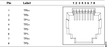
The 10/100 and 10/100/1000 Ethernet ports on switches use RJ-45 connectors and Ethernet pinouts with internal crossovers. Figure B-1 and Figure B-2 show the pinouts.
Figure B-1 10/100 Port Pinouts
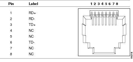
Figure B-2 10/100/1000 Port Pinouts
SFP Module Connectors
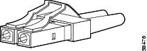
Figure B-3 Fiber-Optic SFP Module LC Connector
 |
Warning |
Dual-Purpose Ports
The 10/100/1000 Ethernet ports on the dual-purpose ports use RJ-45 connectors.
Figure B-4 10/100/1000 Port Pinouts
Cables and Adapters
SFP Module Cables
Each port must match the wave-length specifications on each end of the cable, and for reliable communications, the cable must not exceed the allowable length. Copper 1000BASE-T SFP transceivers use standard four twisted-pair, Category 5 (or greater) cable at lengths up to 328 feet (100 meters).
|
|
(nanometers) |
|
|
|
|
|---|---|---|---|---|---|
1000BASE-LX/LH |
1310 |
MMF2 |
62.5/125 |
500 |
1804 feet (550 m) |
1000BASE-SX |
850 |
MMF |
62.5/125 |
160 |
722 feet (220 m) |
1000BASE-ZX |
1550 |
SMF |
G.6522 |
— |
43.4 to 62 miles |
1000BASE-BX10-U |
1310 TX |
SMF |
G.6522 |
— |
32,810 feet (10 km) |
1000BASE-BX10-D |
1490 TX |
SMF |
G.6524 |
— |
32,810 feet (10 km) |
100BASE-FX (GLC-FE-100FX) |
1310 |
MMF |
50/125 |
500 |
6,562 feet (2 km) |
100BASE-LX (GLC-FE-100LX) |
1310 |
SMF |
G.6522 |
— |
32,810 feet (10 km) |
100BASE-BX (GLC-FE-100BX-D |
1310 TX |
SMF |
G.6522 |
— |
32,810 feet (10 km) |
CWDM |
1470, 1490, 1510, 1530, 1550, 1570, 1590, 1610 |
SMF |
G.6522 |
— |
62 miles (100 km) |
1 Modal bandwidth applies only to multimode fiber. 2 A mode-conditioning patch cord is required. Using an ordinary patch cord with MMF, 1000BASE-LX/LH SFP modules, and a short link distance can cause transceiver saturation, resulting in an elevated bit error rate (BER). When using the LX/LH SFP module with 62.5-micron diameter MMF, you must also install a mode-conditioning patch cord between the SFP module and the MMF cable on both the sending and receiving ends of the link. The mode-conditioning patch cord is required for link distances greater than 984 feet (300 m). 3 1000BASE-ZX SFP modules can send data up to 62 miles (100 km) by using dispersion-shifted SMF or low-attenuation SMF; the distance depends on the fiber quality, the number of splices, and the connectors. 4 A mode-field diameter/cladding diameter = 9 micrometers/125 micrometers. |

Note ![]() When the fiber-optic cable span is less than 15.43 miles (25 km), insert a 5-decibel (dB) or 10-dB inline optical attenuator between the fiber-optic cable plant and the receiving port on the 1000BASE-ZX SFP module.
When the fiber-optic cable span is less than 15.43 miles (25 km), insert a 5-decibel (dB) or 10-dB inline optical attenuator between the fiber-optic cable plant and the receiving port on the 1000BASE-ZX SFP module.
Cable Pinouts
Figure B-5 Two Twisted-Pair Straight-Through Cable Schematic for 10/100 Ports
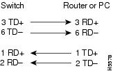
Figure B-6 Two Twisted-Pair Crossover Cable Schematic for 10/100 Ports
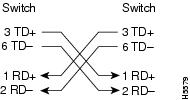
Figure B-7 Four Twisted-Pair Straight-Through Cable Schematic for 1000BASE-T Ports
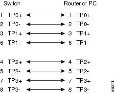
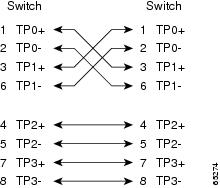
Figure B-8 Four Twisted-Pair Crossover Cable Schematics for 1000BASE-T Ports
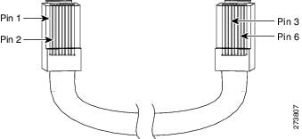
To identify a crossover cable, hold the cable ends side-by-side, with the tab at the back. The wire connected to pin 1 on the left end should be the same color as the wire connected to pin 3 on the right end. The wire connected to pin 2 on the left end should be the same color as the wire connected to pin 6 on the right end.
Figure B-9 Identifying a Crossover Cable
Console Port Adapter Pinouts
The console port uses an 8-pin RJ-45 connector, which is described in Table B-2 and Table B-3. If you did not order a console cable, you need to provide an RJ-45-to-DB-9 adapter cable to connect the switch console port to a PC console port. You need to provide an RJ-45-to-DB-25 female DTE adapter if you want to connect the switch console port to a terminal. You can order an adapter (part number ACS-DSBUASYN=). For console port and adapter pinout information, see Table B-2 and Table B-3.
Table B-2 lists the pinouts for the console port, the RJ-45-to-DB-9 adapter cable, and the console device.
Table B-3 lists the pinouts for the switch console port, RJ-45-to-DB-25 female DTE adapter, and the console device.
Note ![]() The RJ-45-to-DB-25 female DTE adapter is not supplied with the switch. You can order this adapter from Cisco (part number ACS-DSBUASYN=).
The RJ-45-to-DB-25 female DTE adapter is not supplied with the switch. You can order this adapter from Cisco (part number ACS-DSBUASYN=).
 Feedback