Catalyst 2960 Switch Hardware Installation Guide
Bias-Free Language
The documentation set for this product strives to use bias-free language. For the purposes of this documentation set, bias-free is defined as language that does not imply discrimination based on age, disability, gender, racial identity, ethnic identity, sexual orientation, socioeconomic status, and intersectionality. Exceptions may be present in the documentation due to language that is hardcoded in the user interfaces of the product software, language used based on RFP documentation, or language that is used by a referenced third-party product. Learn more about how Cisco is using Inclusive Language.
- Updated:
- April 9, 2008
Chapter: Switch Installation (8-Port Switches)
- Preparing for Installation
- Verifying Switch Operation
- Installing the Switch
- Where to Go Next
Switch Installation (8-Port Switches)
This chapter describes how to start your switch and how to interpret the power-on self-test (POST) that ensures proper operation. It also describes how to install the switch. The installation information in this chapter is specific to the Catalyst 2960-8TC-S, Catalyst 2960-8TC-L, Catalyst 2960G-8TC-L, and Catalyst 2960PD-8TT-L switches. For installation information applicable to the other Catalyst 2960 switches, see Chapter2, “Switch Installation (24- and 48-Port Switches)”
Read the topics and perform the procedures in this order:
For information about connecting to the switch, see Chapter2, “Switch Installation (24- and 48-Port Switches)”
Preparing for Installation
This section covers these topics:
Warnings
These warnings are translated into several languages in the Regulatory Compliance and Safety Information for the Catalyst 2960 Switch guide.

Warning![]() To prevent the switch from overheating, do not operate it in an area that exceeds the maximum recommended ambient temperature of 113°F (45°C). To prevent airflow restriction, allow at least 3 inches (7.6 cm) of clearance around the ventilation openings. Statement 17B
To prevent the switch from overheating, do not operate it in an area that exceeds the maximum recommended ambient temperature of 113°F (45°C). To prevent airflow restriction, allow at least 3 inches (7.6 cm) of clearance around the ventilation openings. Statement 17B
Warning![]() Before working on equipment that is connected to power lines, remove jewelry (including rings, necklaces, and watches). Metal objects will heat up when connected to power and ground and can cause serious burns or weld the metal object to the terminals. Statement 43
Before working on equipment that is connected to power lines, remove jewelry (including rings, necklaces, and watches). Metal objects will heat up when connected to power and ground and can cause serious burns or weld the metal object to the terminals. Statement 43
Warning![]() Do not stack the chassis on any other equipment. If the chassis falls, it can cause severe bodily injury and equipment damage. Statement 48
Do not stack the chassis on any other equipment. If the chassis falls, it can cause severe bodily injury and equipment damage. Statement 48
Warning![]() Ethernet cables must be shielded when used in a central office environment. Statement 171
Ethernet cables must be shielded when used in a central office environment. Statement 171
Warning![]() Warning statement 353 applies only to the Catalyst 2960PD-8TT-L switch:
Warning statement 353 applies only to the Catalyst 2960PD-8TT-L switch:
Warning![]() This product must be connected to a power-over-ethernet (PoE) IEEE 802.3af compliant power source or an IEC60950 compliant limited power source. Statement 353
This product must be connected to a power-over-ethernet (PoE) IEEE 802.3af compliant power source or an IEC60950 compliant limited power source. Statement 353
Warning![]() Do not work on the system or connect or disconnect cables during periods of lightning activity. Statement 1001
Do not work on the system or connect or disconnect cables during periods of lightning activity. Statement 1001
Warning![]() Read the installation instructions before connecting the system to the power source. Statement 1004
Read the installation instructions before connecting the system to the power source. Statement 1004
Warning![]() Class 1 laser product. Statement 1008
Class 1 laser product. Statement 1008
Warning![]() The plug-socket combination must be accessible at all times, because it serves as the main disconnecting device. Statement 1019
The plug-socket combination must be accessible at all times, because it serves as the main disconnecting device. Statement 1019
Warning![]() This equipment must be grounded. Never defeat the ground conductor or operate the equipment in the absence of a suitably installed ground conductor. Contact the appropriate electrical inspection authority or an electrician if you are uncertain that suitable grounding is available. Statement 1024
This equipment must be grounded. Never defeat the ground conductor or operate the equipment in the absence of a suitably installed ground conductor. Contact the appropriate electrical inspection authority or an electrician if you are uncertain that suitable grounding is available. Statement 1024
Warning![]() Ultimate disposal of this product should be handled according to all national laws and regulations. Statement 1040.
Ultimate disposal of this product should be handled according to all national laws and regulations. Statement 1040.
Warning![]() For connections outside the building where the equipment is installed, the following ports must be connected through an approved network termination unit with integral circuit protection: 10/100/1000 Ethernet. Statement 1044
For connections outside the building where the equipment is installed, the following ports must be connected through an approved network termination unit with integral circuit protection: 10/100/1000 Ethernet. Statement 1044
Warning![]() When installing or replacing the unit, the ground connection must always be made first and disconnected last. Statement 1046
When installing or replacing the unit, the ground connection must always be made first and disconnected last. Statement 1046
Warning![]() No user-serviceable parts inside. Do not open. Statement 1073
No user-serviceable parts inside. Do not open. Statement 1073
Warning![]() Installation of the equipment must comply with local and national electrical codes. Statement 1074
Installation of the equipment must comply with local and national electrical codes. Statement 1074
Installation Guidelines
This section is specific to the Catalyst 2960 8-port switches. For information applicable to the other Catalyst 2960 switches, see Chapter2, “Switch Installation (24- and 48-Port Switches)”
When you determine where to place the switch, be sure to observe these requirements:
- The operating environment must be within the ranges listed in Appendix A, “Technical Specifications.”
- Airflow around the switch and through the vents must be unrestricted.
We strongly recommend that you allow at least 3 inches (7.6 cm) of clearance around the ventilation openings.
If the switch is installed in a closed environment or in a multirack assembly, the temperature around it might be greater than normal room temperature.
- Humidity around the switch must not exceed 85 percent.
- Altitude at the installation site must not be greater than 10,000 feet (3,049 meters).
- The bottom of the switch might be hot to the touch if the switch is operating at its maximum temperature 113°F (45°C) and is in an environment that exceeds normal room temperature (such as in a closet, in a cabinet, or in a closed or multirack assembly).
- Do not place any items on the top of the switch.
- Do not stack switches or place switches side-by-side unless they are separated on all sides by at least 3 inches (7.6 cm) of clearance from each other.
- Allow at least 1.75 inches (4 cm) of clearance above each switch in the rack.
- Do not wall-mount the switch with its front panel facing up or sideways. According to safety regulations, wall-mount the switch with its front panel facing down to prevent airflow restriction and to provide easier access to the cables.
- Clearance to the switch front and rear panels meets these conditions
–![]() You can easily read the front-panel indicators.
You can easily read the front-panel indicators.
–![]() Access to ports is sufficient for unrestricted cabling.
Access to ports is sufficient for unrestricted cabling.
–![]() The AC power cord can reach from the AC power outlet to the connector on the switch rear panel.
The AC power cord can reach from the AC power outlet to the connector on the switch rear panel.
- Cabling is away from sources of electrical noise, such as radios, power lines, and fluorescent lighting fixtures. Make sure the cabling is safely away from other devices that might damage the cables.
- For 10/100/1000 ports, cable lengths from the switch to connected devices must be 328 feet (100 meters).
- The cables meet the specifications in Table B-1, which lists the cable specifications for 1000BASE-X and 100BASE-X small form-factor (SFP) modules available for the Catalyst 2960 switch.
When you use shorter lengths of single-mode fiber-optic cable, you might need to insert an inline optical attenuator in the link to avoid overloading the receiver.
When the fiber-optic cable span is less than 15.43 miles (25 km), you should insert a 5-decibel (dB) or 10-dB inline optical attenuator between the fiber-optic cable plant and the receiving port on the 1000BASE-ZX SFP module at each end of the link.
Equipment That You Supply
This section is specific to the Catalyst 2960 8-port switches. For information applicable to the other Catalyst 2960 switches, see Chapter2, “Switch Installation (24- and 48-Port Switches)”
You need this equipment to install the switch:
You can order an optional cable guard to secure cables to the front of the switch and prevent them from being accidentally removed. To order a cable guard, contact your Cisco representative and use these part numbers:
- Catalyst 2960-8TC-L, 2960-8TC-S, and 2960PD-8TT-L switches cable guard part number: CBLGRD-C2960-8TC=
- Catalyst 2960G-8TC-L switch cable guard part number: CBLGRD-C2960G-8TC=
The cable guard is a different part than the cable guide, which you can use to manage a large number of cables in a rack on switches other than the Catalyst 2960-8TC-L and Catalyst 2960G-8TC-L switches.
The switch has security slots in the left and right side panels. You can install an optional cable lock, such as the type that is used to secure a laptop computer, to secure either or both sides of the switch. Cable locks are available from most computer accessory suppliers.
Installing the Catalyst 2960 8-port switches in a 19-inch rack requires an optional bracket kit that is not included with the switch. You can order a kit containing the 19-inch rack-mounting brackets and hardware from Cisco. The kit part number is RCKMNT-19-CMPCT=.
If you want to connect a terminal to the switch console port, you need to provide an RJ-45-to-DB-25 female DTE adapter. You can order a kit (part number ACS-DSBUASYN=) with that adapter from Cisco.
Box Contents
The switch getting started guide on Cisco.com describes the box contents. If any item is missing or damaged, contact your Cisco representative or reseller for support.
Tools and Equipment
You need to supply a number-2 Phillips screwdriver to rack-mount the switch.
Verifying Switch Operation
Before installing the switch in a rack, or on a desk, a shelf, or a wall, you should power on the switch and verify that it passes POST.
To power on the switch, connect one end of the AC power cord to the AC power connector on the switch, and connect the other end of the power cord to an AC power outlet.
You can power the Catalyst 2960PD-8TT-L switch through a 10/100/1000 uplink port, which can receive power from an upstream PoE switch. You can also connect the switch to an AC power adapter on the rear panel. See the “Power Input Port (Catalyst 2960PD-8TT-L Switch)” section for more information.
As the switch powers on, it begins the POST, a series of tests that runs automatically to ensure that the switch functions properly. LEDs can blink during the test. POST lasts approximately 1 minute. When the switch begins POST, the System, Status, Duplex, and Speed LEDs turn green. The System LED blinks green, and the other LEDs remain solid green.
When the POST completes successfully, the System LED remains green. The other LEDs turn off and then reflect the switch operating status. If a switch fails POST, the System LED turns amber.
POST failures are usually fatal. Call Cisco technical support representative if your switch fails POST.
After a successful POST, disconnect the power cord from the switch. Install the switch in a rack, or on a desk, a shelf, or a wall, as described in the “Installing the Switch” section.
Installing the Switch
This section is specific to the Catalyst 2960 8-port switches. For information applicable to the other Catalyst 2960 switches, see Chapter2, “Switch Installation (24- and 48-Port Switches)”
This section describes these installation procedures:
- Desk- or Shelf-Mounting (without Mounting Screws)
- Desk- or Shelf-Mounting (with Mounting Screws)
- Under the Desk- or Shelf-Mounting (with Mounting Screws)
- Wall-Mounting (with Mounting Screws)
- Magnet Mounting
- Rack-Mounting
- Wall-Mounting (with Rack-Mount Brackets)
Desk- or Shelf-Mounting (without Mounting Screws)
This section is specific to the Catalyst 2960 8-port switches. For information applicable to the other Catalyst 2960 switches, see Chapter2, “Switch Installation (24- and 48-Port Switches)”
The switch can be installed on top of a desk or shelf with or without mounting screws. If you do not want to use the mounting screws, follow these steps:
Step 1![]() Locate the adhesive strip with the rubber feet in the accessory kit.
Locate the adhesive strip with the rubber feet in the accessory kit.
Step 2![]() Remove the four rubber feet from the adhesive strip, and attach them to the recessed areas on the bottom of the unit. This prevents the switch from sliding on the desk or shelf.
Remove the four rubber feet from the adhesive strip, and attach them to the recessed areas on the bottom of the unit. This prevents the switch from sliding on the desk or shelf.

Note![]() We strongly recommend that you attach the rubber feet. Doing so helps prevent airflow restriction and overheating.
We strongly recommend that you attach the rubber feet. Doing so helps prevent airflow restriction and overheating.
Step 3![]() Place the switch on the desk or shelf.
Place the switch on the desk or shelf.
Note![]() We strongly recommend that you allow at least 3 inches (7.6 cm) of clearance around the ventilation openings to prevent airflow restriction and overheating.
We strongly recommend that you allow at least 3 inches (7.6 cm) of clearance around the ventilation openings to prevent airflow restriction and overheating.
Do not stack switches or place switches side-by-side unless they are separated on all sides by at least 3 inches (7.6 cm) of clearance from each other.
Do not place any items on the top of the switch.
After the switch is mounted on the desk or shelf, do these tasks to complete the installation:
1.![]() Power on the switch. See the “Verifying Switch Operation”.
Power on the switch. See the “Verifying Switch Operation”.
2.![]() Connect to a 10/100 or 10/100/1000 port, and run Express Setup. See the switch getting started guide for instructions.
Connect to a 10/100 or 10/100/1000 port, and run Express Setup. See the switch getting started guide for instructions.
3.![]() Connect to the front-panel ports. See the “Connecting to the 10/100 and 10/100/1000 Ports” section, the “Connecting to SFP Modules” section, and the “Connecting to a Dual-Purpose Port” section to complete the installation.
Connect to the front-panel ports. See the “Connecting to the 10/100 and 10/100/1000 Ports” section, the “Connecting to SFP Modules” section, and the “Connecting to a Dual-Purpose Port” section to complete the installation.
For configuration instructions about using the command-line interface (CLI) setup program, go to Appendix C, “Configuring the Switch with the CLI-Based Setup Program.”
Desk- or Shelf-Mounting (with Mounting Screws)
This section is specific to the Catalyst 2960 8-port switches. For information applicable to the other Catalyst 2960 switches, see Chapter2, “Switch Installation (24- and 48-Port Switches)”
The switch can be secured to a desk or shelf with mounting screws.
Step 1![]() Locate the screw template. You can use the template to align the mounting screw holes and also as a guide to make sure that you install the screws into the desk or shelf with proper clearance.
Locate the screw template. You can use the template to align the mounting screw holes and also as a guide to make sure that you install the screws into the desk or shelf with proper clearance.
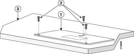
Step 2![]() Position the screw template on top of the desk or shelf so that the two side-by-side slots face the front of the desk or shelf, as shown in Figure 3-1. This ensures that the power cord faces the rear of the desk or shelf after the switch is installed.
Position the screw template on top of the desk or shelf so that the two side-by-side slots face the front of the desk or shelf, as shown in Figure 3-1. This ensures that the power cord faces the rear of the desk or shelf after the switch is installed.
Note![]() Wait before you attach the screw template to the desk or shelf.
Wait before you attach the screw template to the desk or shelf.
Figure 3-1 Installing the Mounting Screws on Top of a Desk or Shelf
|
|
|
||
|
|
|
Step 3![]() Peel the adhesive strip off the bottom of the screw template, and attach it to the top of the desk or shelf.
Peel the adhesive strip off the bottom of the screw template, and attach it to the top of the desk or shelf.
Step 4![]() Use a 0.144-inch (3.7 mm) or a #27 drill bit to drill a 1/2-inch (12.7 mm) hole in the three screw template slots.
Use a 0.144-inch (3.7 mm) or a #27 drill bit to drill a 1/2-inch (12.7 mm) hole in the three screw template slots.
Step 5![]() Insert three screws in the slots on the screw template, and tighten them until they touch the top of the screw template.
Insert three screws in the slots on the screw template, and tighten them until they touch the top of the screw template.
Step 6![]() Remove the screw template from the desk or shelf.
Remove the screw template from the desk or shelf.
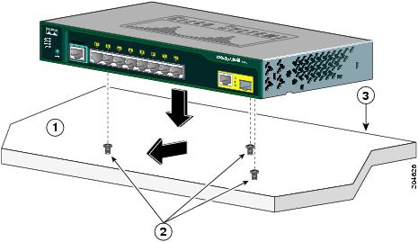
Step 7![]() Place the switch onto the mounting screws, and slide the switch forward until it locks in place, as shown in Figure 3-2.
Place the switch onto the mounting screws, and slide the switch forward until it locks in place, as shown in Figure 3-2.
Note![]() We strongly recommend that you allow at least 3 inches (7.6 cm) of clearance around the ventilation openings to prevent airflow restriction and overheating.
We strongly recommend that you allow at least 3 inches (7.6 cm) of clearance around the ventilation openings to prevent airflow restriction and overheating.
Do not stack switches or place switches side-by-side unless they are separated on all sides with at least 3 inches (7.6 cm) of clearance from each other.
Do not place any items on the top of the switch.
Figure 3-2 Mounting the Switch on Top of a Desk or Shelf
|
|
|
||
|
|
|
After the switch is mounted on the desk or shelf, do these tasks to complete the installation:
1.![]() Power on the switch. See the “Verifying Switch Operation”.
Power on the switch. See the “Verifying Switch Operation”.
2.![]() Connect to a 10/100 or 10/100/1000 port, and run Express Setup. See the switch getting started guide for instructions.
Connect to a 10/100 or 10/100/1000 port, and run Express Setup. See the switch getting started guide for instructions.
3.![]() Connect to the front-panel ports. See the “Connecting to the 10/100 and 10/100/1000 Ports” section, the “Connecting to SFP Modules” section, and the “Connecting to a Dual-Purpose Port” section to complete the installation.
Connect to the front-panel ports. See the “Connecting to the 10/100 and 10/100/1000 Ports” section, the “Connecting to SFP Modules” section, and the “Connecting to a Dual-Purpose Port” section to complete the installation.
For configuration instructions about using the CLI setup program, go to Appendix C, “Configuring the Switch with the CLI-Based Setup Program.”
Under the Desk- or Shelf-Mounting (with Mounting Screws)
This section is specific to the Catalyst 2960 8-port switches. For information applicable to the other Catalyst 2960 switches, see Chapter2, “Switch Installation (24- and 48-Port Switches)”
Step 1![]() Locate the screw template. The template is used to align the mounting screw holes and is also used as a guide to make sure the screws are installed under the desk or shelf with proper clearance.
Locate the screw template. The template is used to align the mounting screw holes and is also used as a guide to make sure the screws are installed under the desk or shelf with proper clearance.
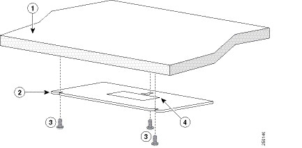
Step 2![]() Position the screw template underneath the desk or shelf so that the two side-by-side slots face the front of the desk or shelf, as shown in Figure 3-3. This ensures that the power cord faces the rear of the desk or shelf after the switch is installed.
Position the screw template underneath the desk or shelf so that the two side-by-side slots face the front of the desk or shelf, as shown in Figure 3-3. This ensures that the power cord faces the rear of the desk or shelf after the switch is installed.
Step 3![]() Peel the adhesive strip off the bottom of the screw template, and attach it to the underside of the desk or shelf.
Peel the adhesive strip off the bottom of the screw template, and attach it to the underside of the desk or shelf.
Figure 3-3 Installing the Mounting Screws Under a Desk or Shelf
|
|
|
||
|
|
|
Step 4![]() Use a 0.144-inch (3.7 mm) or a #27 drill bit to drill a 1/2-inch (12.7 mm) hole in the three screw template slots.
Use a 0.144-inch (3.7 mm) or a #27 drill bit to drill a 1/2-inch (12.7 mm) hole in the three screw template slots.
Step 5![]() Insert three screws in the slots on the screw template, and tighten until they touch the top of the screw template.
Insert three screws in the slots on the screw template, and tighten until they touch the top of the screw template.
Step 6![]() Remove the screw template from underneath the desk or shelf.
Remove the screw template from underneath the desk or shelf.
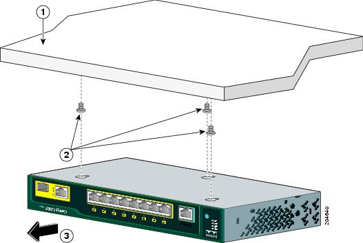
Step 7![]() Place the switch onto the mounting screws, and slide the switch forward until it locks in place, as shown in Figure 3-4.
Place the switch onto the mounting screws, and slide the switch forward until it locks in place, as shown in Figure 3-4.
Note![]() We strongly recommend that you allow at least 3 inches (7.6 cm) of clearance around the ventilation openings to prevent airflow restriction and overheating.
We strongly recommend that you allow at least 3 inches (7.6 cm) of clearance around the ventilation openings to prevent airflow restriction and overheating.
Figure 3-4 Mounting the Switch Under a Desk or Shelf
|
|
|
||
|
|
|
After the switch is mounted under the desk or shelf, do these tasks to complete the installation:
1.![]() Power on the switch. See the “Verifying Switch Operation”.
Power on the switch. See the “Verifying Switch Operation”.
2.![]() Connect to a 10/100 or 10/100/1000 port, and run Express Setup. See the switch getting started guide for instructions.
Connect to a 10/100 or 10/100/1000 port, and run Express Setup. See the switch getting started guide for instructions.
3.![]() Connect to the front-panel ports. See the “Connecting to the 10/100 and 10/100/1000 Ports” section, the “Connecting to SFP Modules” section, and the “Connecting to a Dual-Purpose Port” section to complete the installation.
Connect to the front-panel ports. See the “Connecting to the 10/100 and 10/100/1000 Ports” section, the “Connecting to SFP Modules” section, and the “Connecting to a Dual-Purpose Port” section to complete the installation.
For configuration instructions about using the CLI setup program, go to Appendix C, “Configuring the Switch with the CLI-Based Setup Program.”
Wall-Mounting (with Mounting Screws)
This section is specific to the Catalyst 2960 8-port switches. For information applicable to the other Catalyst 2960 switches, see Chapter2, “Switch Installation (24- and 48-Port Switches)”
The steps in this section show how to mount the switch with the front panel facing down (as shown in Figure 3-5 and Figure 3-6.)
Warning![]() Read the wall-mounting instructions carefully before beginning installation. Failure to use the correct hardware or to follow the correct procedures could result in a hazardous situation to people and damage to the system. Statement 378
Read the wall-mounting instructions carefully before beginning installation. Failure to use the correct hardware or to follow the correct procedures could result in a hazardous situation to people and damage to the system. Statement 378
Note![]() Do not wall-mount the switch with its front panel facing up or sideways. According to safety regulations, wall-mount the switch with its front panel facing down to prevent airflow restriction and to provide easier access to the cables.
Do not wall-mount the switch with its front panel facing up or sideways. According to safety regulations, wall-mount the switch with its front panel facing down to prevent airflow restriction and to provide easier access to the cables.
Follow the steps in this section to install the switch to a wall:
Step 1![]() Locate the screw template. The template is used to align the mounting screw holes.
Locate the screw template. The template is used to align the mounting screw holes.
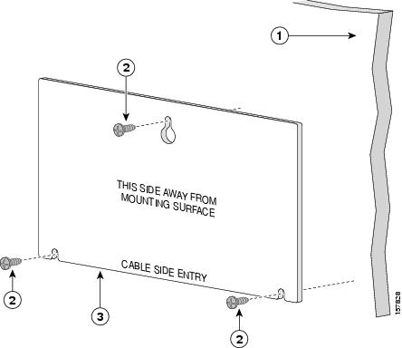
Step 2![]() Position the screw template so that the two side-by-side slots face toward the floor, as shown in Figure 3-5.
Position the screw template so that the two side-by-side slots face toward the floor, as shown in Figure 3-5.
For the best support of the switch and cables, make sure that you attach the switch securely to a wall stud or to a firmly attached plywood mounting backboard.
Step 3![]() Peel the adhesive strip off the bottom of the screw template.
Peel the adhesive strip off the bottom of the screw template.
Figure 3-5 Installing the Mounting Screws on a Wall
|
|
|
||
|
|
|
Step 4![]() Attach the screw template to the wall.
Attach the screw template to the wall.
Step 5![]() Use a 0.144-inch (3.7 mm) or a #27 drill bit to drill a 1/2-inch (12.7 mm) hole in the three screw template slots.
Use a 0.144-inch (3.7 mm) or a #27 drill bit to drill a 1/2-inch (12.7 mm) hole in the three screw template slots.
Step 6![]() Insert three screws in the slots on the screw template, and tighten until they touch the top of the screw template.
Insert three screws in the slots on the screw template, and tighten until they touch the top of the screw template.
Step 7![]() Remove the screw template from the wall.
Remove the screw template from the wall.
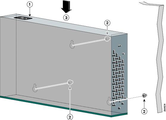
Step 8![]() Place the switch onto the mounting screws, and slide it down until it locks in place, as shown in Figure 3-6.
Place the switch onto the mounting screws, and slide it down until it locks in place, as shown in Figure 3-6.
Figure 3-6 Installing the Switch On a Wall
|
|
|
||
|
|
|
After the switch is mounted on the wall, do these tasks to complete the installation:
1.![]() Power on the switch. See the “Verifying Switch Operation”.
Power on the switch. See the “Verifying Switch Operation”.
2.![]() Connect to a 10/100 or 10/100/1000 port, and run Express Setup. See the switch getting started guide for instructions.
Connect to a 10/100 or 10/100/1000 port, and run Express Setup. See the switch getting started guide for instructions.
3.![]() Connect to the front-panel ports. See the “Connecting to the 10/100 and 10/100/1000 Ports” section, the “Connecting to SFP Modules” section, and the “Connecting to a Dual-Purpose Port” section to complete the installation.
Connect to the front-panel ports. See the “Connecting to the 10/100 and 10/100/1000 Ports” section, the “Connecting to SFP Modules” section, and the “Connecting to a Dual-Purpose Port” section to complete the installation.
For configuration instructions about using the CLI setup program, go to Appendix C, “Configuring the Switch with the CLI-Based Setup Program.”
Magnet Mounting
This section is specific to the Catalyst 2960 8-port switches. For information applicable to the other Catalyst 2960 switches, see Chapter2, “Switch Installation (24- and 48-Port Switches)”
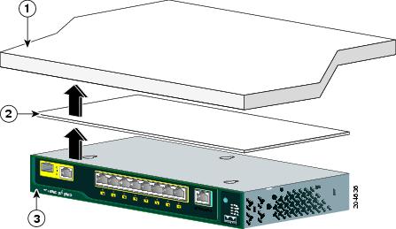
Step 1![]() Place one side of the magnet against the bottom of the switch, as shown in Figure 3-7.
Place one side of the magnet against the bottom of the switch, as shown in Figure 3-7.
Figure 3-7 Mounting the Switch with a Magnet
|
|
|
||
|
|
|
Step 2![]() Mount the magnet and switch on a metal surface.
Mount the magnet and switch on a metal surface.
After the switch is attached to the mounting magnet, do these tasks to complete the installation:
1.![]() Power on the switch. See the “Verifying Switch Operation”.
Power on the switch. See the “Verifying Switch Operation”.
2.![]() Connect to a 10/100 or 10/100/1000 port, and run Express Setup. See the switch getting started guide for instructions.
Connect to a 10/100 or 10/100/1000 port, and run Express Setup. See the switch getting started guide for instructions.
3.![]() Connect to the front-panel ports. See the “Connecting to the 10/100 and 10/100/1000 Ports” section, the “Connecting to SFP Modules” section, and the “Connecting to a Dual-Purpose Port” section to complete the installation.
Connect to the front-panel ports. See the “Connecting to the 10/100 and 10/100/1000 Ports” section, the “Connecting to SFP Modules” section, and the “Connecting to a Dual-Purpose Port” section to complete the installation.
For configuration instructions about using the CLI setup program, go to Appendix C, “Configuring the Switch with the CLI-Based Setup Program.”
Rack-Mounting
This section is specific to the Catalyst 2960 8-port switches. For information applicable to the other Catalyst 2960 switches, see Chapter2, “Switch Installation (24- and 48-Port Switches)”
Installing the Catalyst 2960 8-port switches in a 19-inch rack requires an optional bracket kit that is not included with the switch. You can order a kit containing the 19-inch rack-mounting brackets and hardware from Cisco. The kit part number is RCKMNT-19-CMPCT=.
To install the switch in a 19-inch rack, follow the instructions described in these sections:
Attaching Brackets to the Switch
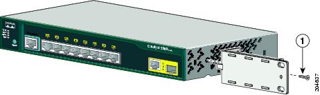
Figure 3-8 shows how to attach a 19-inch bracket to one side of the switch. Follow the same steps to attach the second bracket to the opposite side.
Figure 3-8 Attaching the 19-inch Brackets for Rack-Mounting
|
|
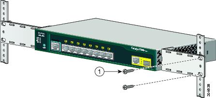
Mounting the Switch in a 19-Inch Rack
After the brackets are attached to the switch, insert the switch into the 19-inch rack, and align the bracket in the rack. Use either the 10-32 pan-head screws or the 12-24 pan-slotted screws to secure the switch in the rack, as shown in Figure 3-9.
Note![]() We strongly recommend that you allow at least 1.75 inches (4 cm) of clearance above each switch in the rack.
We strongly recommend that you allow at least 1.75 inches (4 cm) of clearance above each switch in the rack.
Figure 3-9 Mounting the Switch in a 19-Inch Rack
|
|
After the switch is mounted in the rack, do these tasks to complete the installation:
1.![]() Power on the switch. See the “Verifying Switch Operation”.
Power on the switch. See the “Verifying Switch Operation”.
2.![]() Connect to a 10/100 or 10/100/1000 port, and run Express Setup. See the switch getting started guide for instructions.
Connect to a 10/100 or 10/100/1000 port, and run Express Setup. See the switch getting started guide for instructions.
3.![]() Connect to the front-panel ports. See the “Connecting to the 10/100 and 10/100/1000 Ports” section, the “Connecting to SFP Modules” section, and the “Connecting to a Dual-Purpose Port” section to complete the installation.
Connect to the front-panel ports. See the “Connecting to the 10/100 and 10/100/1000 Ports” section, the “Connecting to SFP Modules” section, and the “Connecting to a Dual-Purpose Port” section to complete the installation.
For configuration instructions about using the CLI setup program, go to Appendix C, “Configuring the Switch with the CLI-Based Setup Program.”
Wall-Mounting (with Rack-Mount Brackets)
To install the Catalyst 2960 8-port switches in a 19-inch rack requires an optional bracket kit that is not included with the switch. You can order a kit containing the 19-inch rack-mounting brackets and hardware from Cisco. The kit part number is RCKMNT-19-CMPCT=.
This section is specific to the Catalyst 2960 8-port switches. For information applicable to the other Catalyst 2960 switches, see Chapter2, “Switch Installation (24- and 48-Port Switches)”
Warning![]() Read the wall-mounting instructions carefully before beginning installation. Failure to use the correct hardware or to follow the correct procedures could result in a hazardous situation to people and damage to the system. Statement 378
Read the wall-mounting instructions carefully before beginning installation. Failure to use the correct hardware or to follow the correct procedures could result in a hazardous situation to people and damage to the system. Statement 378
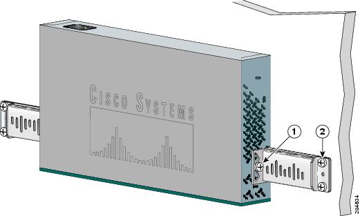
Step 1![]() Attach a 19-inch bracket to one side of the switch. Follow the same steps to attach the second bracket to the opposite side, as shown in Figure 3-10.
Attach a 19-inch bracket to one side of the switch. Follow the same steps to attach the second bracket to the opposite side, as shown in Figure 3-10.
Step 2![]() Mount the switch with the front panel facing down, as shown in Figure 3-10.
Mount the switch with the front panel facing down, as shown in Figure 3-10.
For the best support of the switch and cables, make sure the switch is attached securely to wall studs or to a firmly attached plywood mounting backboard.
Do not wall-mount the switch with its front panel facing up or sideways according to safety regulations. Wall-mount the switch with its front panel facing down to prevent airflow restriction and to provide easier access to the cables.
Figure 3-10 Mounting the Switch on a Wall
|
|
|
After the switch is mounted on the wall, do these tasks to complete the installation:
1.![]() Power on the switch. See the “Verifying Switch Operation”.
Power on the switch. See the “Verifying Switch Operation”.
2.![]() Connect to a 10/100 or 10/100/1000 port, and run Express Setup. See the switch getting started guide for instructions.
Connect to a 10/100 or 10/100/1000 port, and run Express Setup. See the switch getting started guide for instructions.
3.![]() Connect to the front-panel ports. See the “Connecting to the 10/100 and 10/100/1000 Ports” section, the “Connecting to SFP Modules” section, and the “Connecting to a Dual-Purpose Port” section to complete the installation.
Connect to the front-panel ports. See the “Connecting to the 10/100 and 10/100/1000 Ports” section, the “Connecting to SFP Modules” section, and the “Connecting to a Dual-Purpose Port” section to complete the installation.
For configuration instructions about using the CLI setup program, go to Appendix C, “Configuring the Switch with the CLI-Based Setup Program.”
Where to Go Next
If the default configuration is satisfactory, the switch needs no further configuration. You can use any of these management options to change the default configuration:
- Start the device manager, which is in the switch memory, to manage individual and standalone switches. The device manager is a web interface that offers quick configuration and monitoring. You can access the device manager from anywhere in your network through a web browser. For more information, see the device manager online help.
- Start the Network Assistant application, which is described in the Getting Started with Cisco Network Assistant guide. Through this GUI, you can configure and monitor a switch cluster or an individual switch.
- Use the CLI from the console to configure the switch as a member of a cluster or as an individual switch. See the Catalyst 2960 Switch Software Configuration Guide and the Catalyst 2960 Switch Command Reference on Cisco.com for information on using the CLI with a Catalyst 2960 switch.
- Start an SNMP application such as the CiscoView application.
 Feedback