Cisco Nexus 7000 Series NX-OS OTV Configuration Guide
Bias-Free Language
The documentation set for this product strives to use bias-free language. For the purposes of this documentation set, bias-free is defined as language that does not imply discrimination based on age, disability, gender, racial identity, ethnic identity, sexual orientation, socioeconomic status, and intersectionality. Exceptions may be present in the documentation due to language that is hardcoded in the user interfaces of the product software, language used based on RFP documentation, or language that is used by a referenced third-party product. Learn more about how Cisco is using Inclusive Language.
- Updated:
- December 3, 2011
Chapter: Configuring Advanced OTV Features
- Information About Advanced OTV Features
- Licensing Requirements for OTV
- Prerequisites for OTV
- Guidelines and Limitations for OTV
- Guidelines for OTV Multicast
- Default Settings for OTV
- Configuring Advanced OTV Features
- Configuration Modes
- Configuring Authentication for Edge Devices
- Configuring OTV PDU Authentication
- Configuring OTV Adjacency Servers
- Configuring the ARP Neighbor Discovery Timeout for an Overlay
- Disabling the ARP Neighbor Discovery Cache
- Verifying Load Balancing
- Configuring Redistribution
- Tuning OTV
- Verifying the OTV Configuration
- Load Balancing Example
- Monitoring OTV
- Additional References
- Feature History for OTV
Configuring Advanced OTV Features
This chapter describes the advanced configuration for Overlay Transport Virtualization (OTV) on Cisco NX-OS devices.
- Information About Advanced OTV Features
- Licensing Requirements for OTV
- Prerequisites for OTV
- Guidelines and Limitations for OTV
- Guidelines for OTV Multicast
- Default Settings for OTV
- Configuring Advanced OTV Features
- Verifying the OTV Configuration
- Load Balancing Example
- Monitoring OTV
- Additional References
- Feature History for OTV
Information About Advanced OTV Features
OTV uses an overlay control-plane protocol to learn and propagate MAC routing information across the overlay network. The OTV control-plane protocol uses Intermediate-System-to-Intermediate-System (IS-IS) messages to build adjacencies to remote sites and to send MAC route updates to remote sites.
- Building Adjacencies
- Authoritative Edge Device
- MAC Address Reachability Updates
- ARP Neighbor Discovery Cache
- Extended VLANs and VLAN Interfaces
- QoS and OTV
- Virtualization Support
- High Availability and ISSU
Building Adjacencies
OTV builds Layer 2 adjacencies to remote sites on the overlay network through the following modes:
- Autodiscovery based on OTV control-planel hello messages over a common multicast group.
- OTV adjacency server operational mode that manages and distributes a list of all peer edge devices in an overlay
OTV also builds adjacencies with other edge devices in the local site. OTV sends OTV control-plane hello messages on a dedicated VLAN, the site VLAN, to detect other edge devices in the same local site. These edge devices communicate to elect the authoritative edge device for each configured overlay network.
Autodiscovery on the Overlay Network
The overlay routing protocol uses the IS-IS hello messages that are sent to the multicast group address to detect and build adjacencies to remote sites on the overlay network. You configure each site in the overlay network with the same multicast group address. When local and remote sites exchange hellos, a control protocol adjacency is established between the edge devices of both sites. The overlay routing protocol optionally authenticates the remote edge device before building an adjacency to the edge device.
OTV Adjacency Server
Each OTV node provides multicast send capability by replicating at the head-end itself. Each OTV node that sends a multicast packet on a nonmulticast-capable network will unicast replicate the packet. Each OTV node takes a multicast packet that is originated by the upper layers and makes a copy to send to each OTV neighbor that is interested in the multicast packet.
To be able to unicast replicate, each OTV node must know a list of neighbors to replicate to. Rather than configuring the list of all neighbors in each OTV node, you can use a simple means to dynamically identify the neighbors. The set of OTV neighbors might be different for different multicast groups, but the mechanism supports a unicast-replication-list (URL) per multicast group address.
The OTV does not use a replication server, so there are no choke points or longer path delays due to the lack of multicast capability. The multicast data packets, even though they are sent as a unicast message, travel on the same path from the source OTV edge device to each interested party for the group address the multicast is sent to. The only difference is that there are multiple copies being sent from the OTV edge device source.
You must configure which OTV edge device acts as an adjacency server. The OTV edge devices are configured with the IPv4 or IPv6 address of the adjacency server. All other adjacency addresses are discovered dynamically.
When a new site is added, you must configure only the OTV edge devices for the new site with the adjacency server addresses. No other sites in this VPN or other VPNs need additional configuration.
You can have more than one adjacency server per virtual private network (VPN). An adjacency server can serve multiple VPNs.
When an OTV edge device is configured with one or more adjacency server addresses, they are added to the unicast-replication-list (URL). An OTV edge device does not process an alternate server's type length value (TLV) until it believes the primary adjacency server has timed out. The primary and secondary adjacency servers are configured in each OTV edge device. An adjacency server can also be an OTV edge device that connects an OTV site to one or more VPNs.
OTV pushes the secondary adjacency server in the replication list based on the configuration with the primary server.
When you gracefully deconfigure an adjacency server, the client starts using the replication list from the secondary adjacency server and pushes the difference to OTV. If you also deconfigure the secondary adjacency server, the client deletes the replication list entries from OTV immediately.
If you reboot the primary adjacency server, the client starts using the replication list from the secondary adjacency server and pushes the difference to OTV. If the secondary and the primary adjacency servers crash or rebooted, the client makes the replication list entries stale with a timer of 10 minutes. The replication list entries are deleted after 10 minutes in case there is no adjacency server in the network that is advertising the same entries in the replication list.
If you deconfigure or reboot the adjacency server client, the client stops sending hellos to the adjacency server. Consequently, the adjacency server deletes the replication list entry for that client and advertises the deletion to all client nodes. All the nodes delete the adjacency to that client immediately.
If the OTV adjacency is lost with a unicast only adjacency server client, but the adjacency server continues to advertise the unicast-only node, the other nodes continue to send hellos to that node until the adjacency server specifically deletes it from its own list.
Authoritative Edge Device
The authoritative edge device is responsible for all MAC address reachability updates for a VLAN. The overlay routing protocol sends out hello messages on the edge device internal interfaces and over a designated site VLAN to discover other OTV edge devices in the local site. OTV uses a VLAN hashing algorithm to select the authoritiative edge device from one of these local site edge devices.
OTV load balances traffic for the overlay network by sending MAC address reachability updates on different authoritative edge devices, depending on the VLAN of the reachability update.
If the local site has only one edge device, that edge device becomes the authoritative edge device for the VLANs in the configured advertise VLAN range and does not send updates for VLANs that are outside of the configured extended VLAN range.
Dual Site Adjacency and AED Election
OTV uses the dual site adjacency state to determine the authoritative edge device election. A change in the dual site adjacency state also triggers an immediate AED re-election.
Dual site adjacency state considers the following individual state changes for AED election:
- Site adjacency and overlay adjacency down
-
Neighbors remove this edge device from consideration in the AED election.
- Site adjacency down but overlay adjacency up
-
Neighbors continue to use this edge device in any AED elections.
- Site adjacency up but overlay adjacency down
-
Neighbors continue to use this edge device in any AED elections if the neighbor site IS-IS hello messages still include the OTV group address.
AED Election
The AED is elected for each VLAN based on a VLAN ID-based hash computation. The VLAN hash algorithm assigns ordinal numbers from zero to maximum to each edge device in the local site, based on the system ID (based on the system MAC address, by default). The hash algorithm uses the following equation:
f (VLAN ID) = (VLAN ID) % edges
Where edges indicates the number of OTV edge devices in the local site.
If f (VLAN ID) equals the ordinal number for the local edge device, the edge device is authoritative for that VLAN ID. In a site with two edge devices, the VLANs are split as odd and even VLAN IDs on each edge device.
MAC Address Reachability Updates
The OTV control plane uses IS-IS Link State Packets (LSPs) to propagate MAC address to IP address mappings to all edge devices in the overly network. These address mappings contain the MAC address, VLAN ID, and associated IP address of the edge device that the MAC address is reachable from.
The authoritative edge device uses IGMP snooping to learn all multicast MAC addresses in the local site. OTV includes these MAC addresses in a special group-membership LSP (GM-LSP) that is sent to remote edge devices on the overlay network.
ARP Neighbor Discovery Cache
OTV can suppress unnecessary ARP messages from being sent over the overlay network. OTV builds a local Layer 3 to Layer 2 mapping for remote hosts. Any ARP requests from local hosts are served by this ARP Neighbor Discovery cache.
Extended VLANs and VLAN Interfaces
A VLAN can either have Layer 3 connectivity through a VLAN interface (SVI) or the VLAN can be extended over OTV. If you have a design scenario that requires the VLAN to be both extended over OTV to a remote site and have Layer 3 connectivity through a VLAN interface, you must configure OTV in a separate VDC from the VDC that contains the VLAN interfaces.
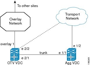
In this figure, the Agg VDC contains all the configuration and physical links for the Aggregation Layer of a data center. The Agg VDC also includes the VLAN interfaces (SVIs) for any VLANs that need Layer 3 connectivity. The Agg VDC is connected to the OTV VDC through a loopback cable over a trunk port. This trunk port carries any VLAN traffic that needs to be extended over the overlay network.
The OTV VDC also includes a trunk port that accepts this VLAN traffic. All OTV configuration exists in the OTV VDC. The overlay interface has an extended VLAN range that includes VLANs from the Agg VDC that have Layer 3 connectivity through VLAN interfaces. These extended VLANs are isolated in a separate VDC from the VLAN interfaces in the Agg VDC. The Agg VDC decides on whether a Layer 2 frame is forwarded to the local VLAN interface to Layer 3 or whether the Layer 2 frame is sent over the trunk port to the OTV VDC and encapsulated for the overlay network.
 Note |
OTV is transparent to the Aggregation Layer and the rest of the data center site in this example. |
QoS and OTV
By default, OTV copies the QoS DSCP or 802.1p values from the original packet to the IP header of the OTV IP packet to propagate the QoS DSCP value across the overlay network. This action ensures that the encapsulated IP packet receives the same differentiated QoS policy that the original packet received before it was extended across the overlay network.
To override this default behavior, you must apply a QoS policy to the extended VLAN. This policy can set the OTV IP encapsulation DSCP values based on a chosen match criteria. At the remote site, OTV removes this VLAN QoS policy to maintain the QoS policy for the original packet.
Virtualization Support
The software supports multiple instances of OTV that run on the same system. OTV supports virtual routing and forwarding instances (VRFs) on the physical interface that is associated with the overlay interface. VRFs exist within virtual device contexts (VDCs). By default, the software places you in the default VDC and default VRF unless you specifically configure another VDC and VRF.
In Cisco NX-OS Release 5.0(3) and later releases, the OTV join interface must belong to the default VRF. The VRF of the physical interface that is associated with the overlay interface determines the Layer 3 reachability to the remote edge device.
High Availability and ISSU
OTV supports stateful restarts and stateful switchovers. A stateful restart occurs when the OTV process fails and is restarted. A stateful switchover occurs when the active supervisor switches to the standby supervisor. The software applies the run-time configuration after the switchover.
Any upgrade from an image that is earlier than Cisco NX-OS 5.2(1) to an image that is Cisco NX-OS 5.2(1) or later in an OTV network is disruptive. A software image upgrade from Cisco NX-OS 5.2(1) or later to Cisco NX-OS 6.0(1) is not disruptive.
You must upgrade all edge devices in the site and configure the site identifier on all edge devices in the site before traffic is restored. You can prepare OTV for ISSU in a dual-homed site to minimize this disruption. An edge device with an older Cisco NX-OS release in the same site can cause traffic loops. You should upgrade all edge devices in the site during the same upgrade window. You do not need to upgrade edge devices in other sites as OTV interoperates between sites with different Cisco NX-OS versions.
Licensing Requirements for OTV
The following table shows the licensing requirements for this feature:
| Product |
License Requirement |
|---|---|
| Cisco NX-OS |
OTV requires the Transport Services license. For a complete explanation of the Cisco NX-OS licensing scheme and how to obtain and apply licenses, see the Cisco NX-OS Licensing Guide. |
Prerequisites for OTV
OTV has the following prerequisites:
- Globally enable the OTV feature.
- Enable IGMPv3 on the join interfaces.
- Ensure connectivity for the VLANs to be extended to the OTV edge device.
- If you configure VDCs, install the Advanced Services license and enter the desired VDC (see the Cisco Nexus 7000 Series NX-OS Virtual Device Context Configuration Guide).
Guidelines and Limitations for OTV
OTV has the following configuration guidelines and limitations:
- If the same device serves as the default gateway in a VLAN interface and the OTV edge device for the VLANs being extended, configure OTV on a device (VDC or switch) that is separate from the VLAN interfaces (SVIs).
- An overlay interface will only be in an up state if the overlay interface configuration is complete and enabled (no shutdown). The join interface has to be in an up state.
- Configure the join interface and all Layer 3 interfaces that face the IP core between the OTV edge devices with the highest maximum transmission unit (MTU) size supported by the IP core. OTV sets the Don't Fragment (DF) bit in the IP header for all OTV control and data packets so the core cannot fragment these packets.
- Only one join interface can be specified per overlay. You can decide to use one of the following methods: For a higher resiliency, you can use a port-channel, but it is not mandatory. There are no requirements for 1 Gigabit-Ethernet versus 10 Gigabit-Ethernet or dedicated versus shared mode.
- If your network includes a Cisco Nexus 1000V switch, ensure that switch is running 4.0(4)SV1(3) or later releases. Otherwise, disable Address Resolution Protocol(ARP) and Neighbor Discovery (ND) suppression for OTV.
- The transport network must support PIM sparse mode (ASM) or PIM-Bidir multicast traffic.
- OTV is compatible with a transport network configured only for IPv4. IPv6 is not supported.
- Do not enable PIM on the join-interface.
- Do not configure OTV on an F-series module.
- Ensure the site identifier is configured and is the same for all edge devices on a site. OTV brings down all overlays when a mismatched site identifier is detected from a neighbor edge device and generates a system message.
- Any upgrade from an image that is earlier than Cisco NX-OS 5.2(1) to an image that is Cisco NX-OS 5.2(1) or later in an OTV network is disruptive. A software image upgrade from Cisco NX-OS 5.2(1) or later to Cisco NX-OS 6.0(1) is not disruptive.
- You must upgrade all edge devices in the site and configure the site identifier on all edge devices in the site before traffic is restored. An edge device with an older Cisco NX-OS release in the same site can cause traffic loops. You should upgrade all edge devices in the site during the same upgrade window. You do not need to upgrade edge devices in other sites as OTV interoperates between sites with different Cisco NX-OS versions.
Guidelines for OTV Multicast
OTV has the following guidelines for multicast configuration:
- OTV does not require Protocol Independent Multicast (PIM) to be configured on an edge device. If you configure PIM on the edge device, ensure that the rendezvous point (RP) is also configured on the edge device. The reverse-path forwarding (RPF) interface for (*.PG) should be join interface.
- Do not configure PIM on a join interface of the edge device.
- You should configure IGMP version 3 on both sides of the join interface link. The OTV edge devices send IGMP (S,G) joins the edge devices in other sites in the same VPN. If you must configure IGMPv2, you must configure the last-hop router to do an ssm-translate, and the data-group range for the overlay interface must be SSM.
- You can directly connect edge devices in different sites.
- If there is no router in the site, you must configure the ip igmp snooping querier command in VLAN configuration mode on the switch.
- IGMP snooping for VLANs extended over the overlay network is enabled by default and should not be disabled. IGMP reports that are originated in the site are not sent across the core. Enough multicast state is built in the edge devices and core routers so that traffic can be sent from the source in the source site to a destination in the destination site.
- You do not need to configure a unicast routing protocol on join interfaces, although in most situations, one will be configured.
- You must disable optimized multicast forwarding (OMF) in IGMP snooping in OTV edge devices for IPv6 unicast or multicast traffic to flow across an OTV overlay network.
Default Settings for OTV
| Parameters |
Default |
|---|---|
| OTV feature |
Disabled |
Advertised VLANs |
None |
ARP and ND suppression |
Enabled |
Graceful restart |
Enabled |
Site VLAN |
1 |
Site identifier |
0x0 |
IS-IS hello interval |
10 seconds |
IS-IS hello multiplier |
3 |
IS-IS CSNP interval |
10 seconds |
IS-IS LSP interval |
33 milliseconds |
Configuring Advanced OTV Features
This section describes the tasks for configuring advanced OTV features.
Note |
If you are familiar with the Cisco IOS CLI, be aware that the Cisco NX-OS commands for this feature might differ from the Cisco IOS commands that you would use. |
- Configuration Modes
- Configuring Authentication for Edge Devices
- Configuring OTV PDU Authentication
- Configuring OTV Adjacency Servers
- Configuring the ARP Neighbor Discovery Timeout for an Overlay
- Disabling the ARP Neighbor Discovery Cache
- Verifying Load Balancing
- Configuring Redistribution
- Tuning OTV
Configuration Modes
The following sections show how to enter each of the configuration modes. From a mode, you can enter the question mark (?) command to display the commands available in that mode.
Interface Configuration Mode Example
The following example shows how to enter the overlay interface configuration mode:
switch# configure terminal
switch(config)# interface overlay 2
switch(config-if-overlay)#
OTV IS-IS VPN Configuration Mode Example
The following example shows how to enter OTV IS-IS VPN configuration mode:
switch# configure terminal
switch(config)# otv-isis default
switch(config-router)# vpn Test1
switch(config-router-vrf)#
Configuring Authentication for Edge Devices
You can configure authentication for the OTV control-plane protocol hello messages. OTV use hello authentication to authenticate a remote site before OTV creates an adjacency to that remote site. Each overlay network uses a unique authentication key. An edge device only creates an adjacency with a remote site that shares the same authentication key and authentication method.
OTV supports the following authentication methods:
1. configure terminal
2. interface overlay interface
3. otv isis authentication-check
4. otv isis authentication-type {cleartext | md5}
5. otv isis authentication keychain keychain-name
6. (Optional) show otv overlay [interface]
7. (Optional) copy running-config startup-config
DETAILED STEPS
Configuring OTV PDU Authentication
You can configure OTV to authenticate all incoming OTV control-plane protocol data units (PDUs). OTV supports the following authentication methods:
Note |
OTV control-plane protocol hello authentication is configured separately. |
Enable the OTV feature.
1. configure terminal
2. otv-isis default
3. vpn overlay-name
4. authentication-check
5. authentication-type {cleartext | md5}
6. authentication keychain keychain-name
7. (Optional) show otv isis hostname vpn [overlay-name | all]
8. (Optional) copy running-config startup-config
DETAILED STEPS
Configuring OTV Adjacency Servers
You can either configure the local edge device to act as an adjacency server, or you can configure a remote adjacency server.
Enable the OTV feature.
1. configure terminal
2. interface overlay interface
3. (Optional) otv adjacency-server unicast-only
4. (Optional) otv use-adjacency-server primary-ip-address [secondary-ip-address] unicast-only
5. (Optional) show otv adjacency [overlay if-number | vpn vpn-name] [detail]
6. (Optional) copy running-config startup-config
DETAILED STEPS
Configuring the ARP Neighbor Discovery Timeout for an Overlay
Beginning with NX-OS Release 6.1(1), you can configure how long a dynamically learned IP address and its corresponding MAC address remain in the OTV ARP (Address Resolution Protocol) and ND (Neighbor Discovery) cache. This command applies to all IP addresses learned for this overlay regardless of whether they were learned on the overlay interface or on an associated access interface.
1. configure terminal
2. interface overlay interface
3. otv arp-nd timeout seconds
4. (Optional) copy running-config startup-config
DETAILED STEPS
switch # configure terminal
switch(config)# interface overlay 1
switch(config-if-overlay)# otv arp-nd timeout 70
switch(config-if-overlay)# copy running-config startup-config
Disabling the ARP Neighbor Discovery Cache
An ARP cache is maintained by every OTV edge device and is populated by snooping ARP replies. Initial ARP requests are broadcasted to all sites, but subsequent ARP requests are suppressed at the edge device and answered locally. OTV edge devices can reply to ARPs on behalf of remote hosts. Use the following procedure to disable this functionality.
1. configure terminal
2. interface overlay interface
3. no otv suppress-arp-nd
4. (Optional) show otv arp-nd-cache [interface]
5. (Optional) copy running-config startup-config
DETAILED STEPS
Verifying Load Balancing
You can load balance overlay network traffic across different edge devices in a local site. OTV uses the site VLAN to discover all edge devices in the local site. OTV then dynamically assigns VLANs to an authoritative edge device for each VLAN, based on the VLAN ID, the number of edge devices in the local site, and the system ID of the edge device. Load balancing is achieved because each edge device is authoritative for a subset of all VLANs that are transported over the overlay.
1. configure terminal
2. otv site-vlan vlan-id
3. (Optional) show otv site [all] [detail]
4. (Optional) show otv [overlay-interface] vlan vlan-id authoritative [detail]
DETAILED STEPS
Examples
The following example shows the output for the show otv vlan authoritative detail command:
switch(config)# show otv vlan authoritative detail
OTV VLAN Configuration Information
Legend: F - Forwarding B - Blocked
VLAN-ID  VlanState           Switchport/    External       Overlay
                             Forward Count  Interface      Group
Configuring Redistribution
You can configure a route map to filter OTV updates on an overlay network. The route map can use the following match options:
- match mac-list
-
List of MAC addresses to match against. Only MAC addresses that match a mac-list entry are redistributed across the overlay network.
- match vlan
-
VLAN ID to match against. OTV redistributes the MAC routes that match this VLAN ID.
See the Cisco Nexus 7000 Series NX-OS Unicast Routing Configuration Guide, for more information on route maps and MAC address lists.
1. configure terminal
2. otv-isis default
3. vpn overlay-name
4. redistribute filter route-map map-name
5. (Optional) show otv isis redistribute route [vpn overlay-name | summary]
6. (Optional) copy running-config startup-config
DETAILED STEPS
Tuning OTV
You can tune parameters for the overlay routing protocol.
Note |
We recommend that only very experienced users of OTV perform these configurations. |
1. configure terminal
2. interface overlay interface
3. (Optional) otv isis csnp-interval seconds
4. (Optional) otv isis hello-interval seconds
5. (Optional) otv isis hello-multiplier mulltiplier
6. (Optional) otv isis hello-padding
7. (Optional) otv isis lsp-interval msec
8. (Optional) otv isis metric metric
9. (Optional) otv isis priority dis-priority
10. (Optional) show otv isis [isis-tag] [interface interface]
11. (Optional) copy running-config startup-config
DETAILED STEPS
Verifying the OTV Configuration
To display the OTV configuration, perform one of the following tasks:
| Command |
Purpose |
|---|---|
show running-configuration otv [all] |
Displays the running configuration for OTV. |
| show otv overlay [interface] |
Displays information about overlay interfaces. |
show otv adjacency [detail] |
Displays information about the adjacencies on the overlay network. |
show otv [overlay interface] [vlan [ vlan-range] [authoritative | detail]] |
Displays information about VLANs that are associated with an overlay interface. |
show otv site [ all] |
Displays information about the local site. |
show otv [route [interface [neighbor-address ip-address]] [vlan vlan-range] [mac-address]] |
Displays information about the OTV routes. |
show mac address-table |
Displays information about MAC addresses. |
Load Balancing Example
Basic OTV Network
The following example displays how to configure load balancing on two edge devices in the same site:
Edge Device 1 interface ethernet 2/1 ip address 192.0.2.1/24 ip igmp version 3 no shutdown vlan 5-10 feature otv otv site-identifier 256 interface overlay 1 otv control-group 239.1.1.1 otv data-group 239.1.1.0/29 otv join-interface ethernet 2/1 otv extend-vlan 5-10 no shutdown Edge Device 2 interface ethernet 1/1 ip address 192.0.2.16/24 ip igmp version 3 no shutdown vlan 5-10 feature otv otv site-identifier 256 interface overlay 2 otv control group 239.1.1.1 otv data-group 239.1.1.0/29 otv join-interface ethernet 1/1 otv extend-vlan 5-10 no shutdown
Monitoring OTV
To monitor OTV, perform one of the following tasks:
| Command |
Purpose |
|---|---|
show otv orib clients |
Displays information about the ORIB clients. |
show otv route [overlay interface | vlan vlan-id | vpn vpn-name] |
Shows unicast MAC routes. |
show otv mroute [overlay interface | vlan vlan-id | vpn vpn-name] |
Displays information about multicast MAC routes. |
show otv statistics multicast vlan vlan-id |
Shows OTV statistics. |
show otv isis statistics {* | overlay interface } |
Shows statistics for the OTV control-plane protocol. |
To clear OTV information, perform the following task:
| Command |
Purpose |
|---|---|
clear otv isis statistics { * | overlay interface } |
Clears OTV statistics. |
Additional References
This section includes additional information related to implementing OTV.
Related Documents
| Related Topic | Document Title |
|---|---|
| Cisco NX-OS licensing |
Cisco NX-OS Licensing Guide |
| Command reference |
Cisco Nexus 7000 Series NX-OS OTV Command Reference |
Standards
| Standards |
Title |
|---|---|
| No new or modified standards are supported by this feature, and support for existing standards has not been modified by this feature. |
— |
Feature History for OTV
| Feature Name |
Releases |
Feature Information |
|---|---|---|
ARP Neighbor Discovery timeout |
6.1(1) |
Added configuration support for ARP ND timeout. |
OTV Adjacency Server |
5.2(1) |
Added OTV Adjacency Server support. |
Dual Site Adjacency |
5.2(1) |
Added site identifier support for dual site adjacency. |
Extended VLAN range |
5.2(1) |
Added support to add or remove VLANs to the extended VLAN range. |
IPv6 unicast forwarding and multicast flooding |
5.2(1) |
Added support for IPv6 unicast forwarding and multicast flooding across the OTV overlay. |
Configuration limits |
5.2(1) |
Enhanced the OTV scalability limits. |
| OTV |
5.0(3) |
OTV was introduced. |
 Feedback