Cisco Nexus 7000 Series NX-OS Intelligent Traffic Director Configuration Guide
Bias-Free Language
The documentation set for this product strives to use bias-free language. For the purposes of this documentation set, bias-free is defined as language that does not imply discrimination based on age, disability, gender, racial identity, ethnic identity, sexual orientation, socioeconomic status, and intersectionality. Exceptions may be present in the documentation due to language that is hardcoded in the user interfaces of the product software, language used based on RFP documentation, or language that is used by a referenced third-party product. Learn more about how Cisco is using Inclusive Language.
- Updated:
- October 3, 2014
Chapter: Configuring ITD
- Finding Feature Information
- Information About ITD
Configuring ITD
This chapter describes how to configure Intelligent Traffic Director (ITD) on the Cisco NX-OS device.
- Finding Feature Information
- Information About ITD
- Licensing Requirements for ITD
- Prerequisites for ITD
- Guidelines and Limitations for ITD
- Configuring ITD
- Verifying the ITD Configuration
- Warnings and Error Messages for ITD
- Configuration Examples for ITD
- Related Documents for ITD
- Standards for ITD
- Feature History for ITD
Finding Feature Information
Your software release might not support all the features documented in this module. For the latest caveats and feature information, see the Bug Search Tool at https://tools.cisco.com/bugsearch/ and the release notes for your software release. To find information about the features documented in this module, and to see a list of the releases in which each feature is supported, see the "New and Changed Information"chapter or the Feature History table in this chapter.
Information About ITD
Intelligent Traffic Director (ITD) is an intelligent, scalable clustering and load-balancing engine that addresses the performance gap between a multi-terabit switch and gigabit servers and appliances. The ITD architecture integrates Layer 2 and Layer 3 switching with Layer 4 to Layer 7 applications for scale and capacity expansion to serve high-bandwidth applications.
ITD provides adaptive load balancing to distribute traffic to an application cluster. With this feature on the Cisco Nexus 7000 Series switch, you can deploy servers and appliances from any vendor without a network or topology upgrade.
- ITD Feature Overview
- Benefits of ITD
- Deployment Modes
- Device Groups
- VRF Support
- Load Balancing
- Hot Standby
- Multiple Ingress Interfaces
- System Health Monitoring
- Failaction Reassignment
ITD Feature Overview
Intelligent Traffic Director offers simplicity, flexibility, and scalability. This makes it easier for customers to deploy a traffic distribution solution in a wide variety of use cases without the use of any external hardware. Here are a few common deployment scenarios:
-
Firewall cluster optimization
-
Predictable redundancy and scaling of security services such as Intrusion Prevention System, Intrusion Detection System and more.
-
High-scale DNS solutions for enterprise and service providers
-
Scaling specialized web services such as SSL Accelerators, HTTP compression, and others
-
Using the data plane of the network to distribute high bandwidth applications
The following example use cases are supported by the Cisco ITD feature:
-
Load-balance traffic to 256 servers of 10Gbps each.
-
Load-balance to a cluster of Firewalls. ITD is much superior than policy-based routing (PBR).
-
Scale up NG IPS and WAF by load-balancing to standalone devices.
-
Scale the WAAS / WAE solution.
-
Scale the VDS-TC (video-caching) solution.
-
Replace ECMP/Port-channel to avoid re-hashing. ITD is resilient.
Benefits of ITD
ITD on the Cisco NX-OS switch enables the following:
Operational Simplicity
-
Transparent connectivity for appliance and server clustering
-
Optimized for fast and simple provisioning
Investment Protection
Deployment Modes
One-Arm Deployment Mode
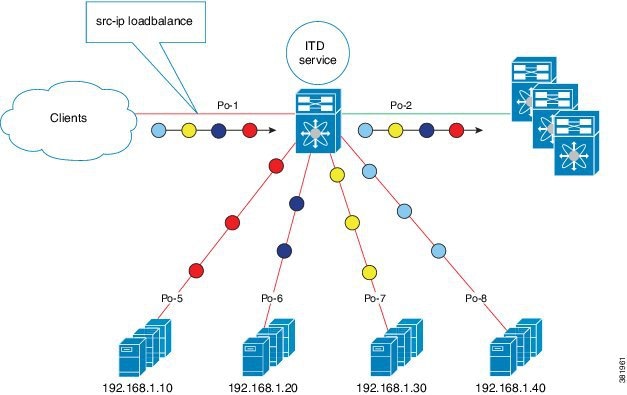
You can connect servers to the Cisco NX-OS device in one-arm deployment mode. In this topology, the server is not in the direct path of client or server traffic, which enables you to plug in a server into the network with no changes to the existing topology or network.
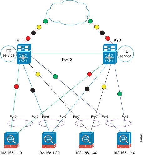
One-Arm Deployment Mode with VPC
The ITD feature supports an appliance cluster connected to a virtual port channel (vPC). The ITD service runs on each Cisco NX-OS switch and ITD programs each switch to provide flow coherent traffic passing through the nodes.
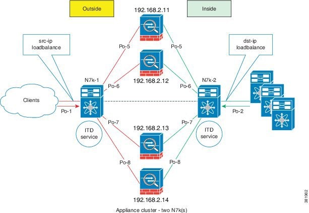
Sandwich Deployment Mode
The sandwich deployment mode uses two Cisco NX-OS 7000 Series switches to provide stateful handling of traffic.
The main requirement in this mode is that both forward and reverse traffic of a flow must go through the same appliance. Examples include firewalls and load balancer deployments, where traffic between client and server must flow through the same appliance.
The key features are:
-
An ITD service for each network segment—one for outside network and another for inside network.
-
A source-IP load balancing scheme where the ITD service operates on the interface that connects to the outside world in an ingress direction.
-
A destination-IP load balancing scheme where the ITD service operates on the interface that connects to the servers in the ingress direction.
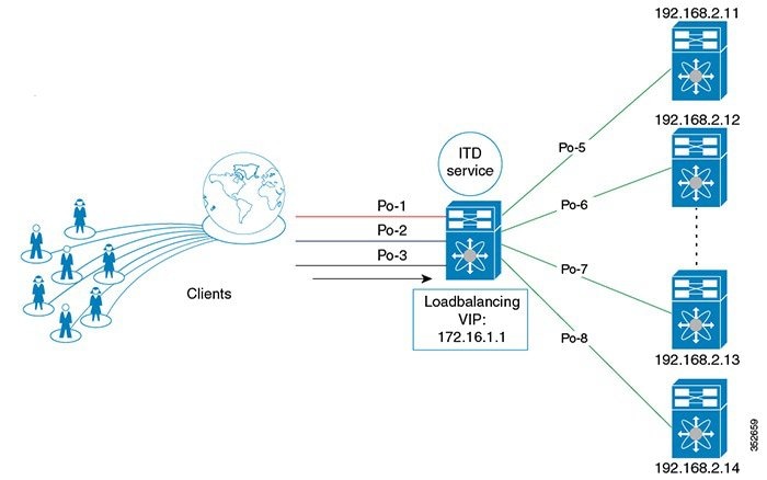
Server Load-Balancing Deployment Mode
The ITD service can be configured to host a virtual IP (VIP) on a Cisco NX-OS 7000 Series switch. Internet traffic destined for the VIP will be load balanced to the active nodes. Unlike traditional server load balancers, source NAT is not needed as the ITD service is not a stateful load balancer.
 Note | You need to configure ITD service similarly on each Cisco NX-OS 7000 Series switch. The ITD service configuration needs to be done manually on each switch. |
Device Groups
The ITD feature supports device groups. When you configure a device group you can specify the following:
VRF Support
The ITD service can be configured in the default VRF as well as non-default VRFs.
Ingress interface(s) and device-group nodes must all belong to the same VRF for the ITD service to redirect traffic. You must ensure that all ingress interface(s) and node members of the associated device group are all reachable in the configured VRF.
Load Balancing
The ITD feature enables you to configure specific load-balancing options by using the loadbalance command.
The optional keywords for the loadbalance command are as follows:
-
buckets—Specifies the number of buckets to create. Buckets must be configured in powers of two. One or more buckets are mapped to a node in the cluster. If you configure more buckets than the number of nodes, the buckets are applied in round robin fashion across all the nodes.
-
mask-position— Specifies the mask position of the load balancing. This keyword is useful when a packet classification has to be made based on specific octets or bits of an IP addresses. By default the system uses the last octet's starting most significant bits (MSBs).
If you prefer to use nondefault bits/octets, you can use the mask-position keyword to provide the starting point at which bits the traffic classification is to be made. For example, you can start at the 8th bit for the second octet and the 16th bit for the third octet of an IP address.
-
src or dst ip— Specifies load balancing based on source or destination IP address.
-
src ip or src ip-l4port— Specifies load balancing based on source IP address, or source IP address and source L4 port.
-
dst ip or dst ip-l4port— Specifies load balancing based on destination IP address, or destination IP address and destination L4 port.
Hot Standby
ITD supports N+1 redundancy where M nodes can act as standby nodes for N active nodes.
When an active node fails, ITD looks for an operational standby node and selects the first available standby node to replace the failed node. ITD reconfigures the switch to redirect the traffic segment that was originally headed toward the failed node to the newly active node. The service does not impose any fixed mapping of standby nodes to active nodes.
When the failed node becomes operational again, it is reinstated as an active node and traffic from the acting standby node is redirected back to the original node and the standby node reverts to the pool of standby nodes.
When multiple nodes fail, traffic destined to all failed nodes gets redirected to the first available standby node.
A node can be configured as a standby at the node-level or device-group-level. A node-level standby receives traffic only if its associated active node fails. A device-group-level standby receives traffic if any of the active nodes fail.
Multiple Ingress Interfaces
You can configure the ITD service to apply traffic redirection policies on multiple ingress interfaces. This feature allows you to use a single ITD service to redirect traffic arriving on different interfaces to a group of nodes. The ingress interface command enables you to configure multiple ingress interfaces.
The same ingress interface can be configured in two ITD services, allowing one IPv4 ITD service and one IPv6 ITD service.
Configuring the same ingress interface in both IPv4 and IPv6 ITD services allows both IPv4 and IPv6 traffic to arrive on the same ingress interface. An IPv4 ITD policy is applied to redirect IPv4 traffic and an IPv6 ITD policy is applied to redirect IPv6 traffic.
Note | Make sure the ingress interface is not configured in more than one IPv4 ITD service and/or more than one IPv6 ITD service. The system does not automatically check this. |
System Health Monitoring
Monitor Node
The ITD health monitoring module periodically monitors nodes to detect any failure and to handle failure scenarios.
ICMP, TCP, UDP, DNS and HTTP probes are supported to probe each node periodically for health monitoring. A probe can be configured at the device-group level or at node-level. A probe configured at the device-group level is sent to each node member of the device-group. A probe configured at a node-level is sent only to the node it is associated with. If a node-specific probe is configured, only that probe is sent to the node. For all the nodes that do not have node-specific probe configuration, the device-group level probe (if configured) is sent.
Note | HTTPS probe is not supported on ITD. |
IPv4 Control Probe for IPv6 Data Nodes
For an IPv6 node (in an IPv6 device-group), if the node is a dual-homed node (that is, it supports IPv4 and IPv6 network interfaces), an IPv4 probe can be configured to monitor the health. Since IPv6 probes are not supported, this provides a way to monitor health of IPv6 data nodes using a IPv4 probe.
Note | IPv6 probes are not supported. |
Health of an Interface Connected to a Node
ITD leverages the IP service level agreement (IP SLA) feature to periodically probe each node. The probes are sent at a one second frequency and sent simultaneously to all nodes. You can configure the probe as part of the cluster group configuration. A probe is declared to have failed after retrying three times.
Node Failure Handling
Upon marking a node as down, the ITD performs the following tasks automatically to minimize traffic disruption and to redistribute the traffic to remaining operational nodes:
-
Determines if a standby node is configured to take over from the failed node.
-
Identifies the node as a candidate node for traffic handling, if the standby node is operational.
-
Redefines the standby node as active for traffic handling, if an operational standby node is available.
-
Programs automatically to reassign traffic from the failed node to the newly active standby node.
Monitor Peer ITD Service
For sandwich mode cluster deployments, the ITD service runs on each Cisco NX-OS 7000 series switch. The health of the ITD channel is crucial to ensure flow coherent traffic passing through cluster nodes in both directions.
Each ITD service probes its peer ITD service periodically to detect any failure. A ping is sent every second to the peer ITD service. If a reply is not received it is retried three times. The frequency and retry count are not configurable.
Note | Since only a single instance of the ITD service is running on the switch in one-arm mode deployment, monitoring of the peer ITD is not applicable. |
ITD channel failure handling
If the heartbeat signal is missed three times in a row, then the ITD channel is considered to be down.
While the ITD channel is down, traffic continues to flow through cluster nodes. However, since the ITD service on each switch is not able to exchange information about its view of the cluster group, this condition requires immediate attention. A down ITD channel can lead to traffic loss in the event of a node failure.
Failaction Reassignment
Failaction for ITD enables traffic on the failed nodes to be reassigned to the first available active node. Once the failed node comes back, it automatically resumes serving the connections. The failaction command enables this feature.
When the node is down, the traffic bucket associated with the node is reassigned to the first active node found in the configured set of nodes. If the newly reassigned node also fails, traffic is reassigned to the next available active node. Once the failed node becomes active again, traffic is diverted back to the new node and resumes serving connections.
Note | You must configure probe under an ITD device group, before enabling the failaction feature. |
- Failaction Reassignment Without a Standby Node
- Failaction Reassignment with a Standby Node
- No Failaction Reassignment
Failaction Reassignment Without a Standby Node
When the node is down, the traffic bucket associated with the node is reassigned to the first active node found in the configured set of nodes. If the newly reassigned node also fails, the traffic bucket is reassigned to the next available active node. Once the failed node comes back and becomes active, the traffic is diverted back to the new node and starts serving the connections.
If all the nodes are down, the packets get routed automatically.
Failaction Reassignment with a Standby Node
When the node is down and if the standby is active, the traffic serves the connections and there is no change in the bucket assignment. When both the active and standby nodes are down, the traffic bucket associated with the node is reassigned to the first active node found in the configured set of nodes. If the newly reassigned node also fails, the traffic bucket is reassigned to the next available active node. Once the failed node comes back up and becomes active, the traffic is diverted back to the new node and begins serving connections.
-
When the node goes down (probe failed) and when there is a working standby node, traffic is directed to the first available standby node.
-
When all nodes are down including the standby node, the traffic is reassigned to the first available active node.
-
When the node comes up (probe success) from failed state, the node that came up starts handling the connections.
-
If all the nodes are down, the packets are routed automatically.
No Failaction Reassignment
When failaction node reassignment is not configured, there are two possible scenarios:
- No Failaction Reassignment with a Probe Configured
- No Failaction Reassignment without a Probe Configured
No Failaction Reassignment with a Probe Configured
The ITD probe can detect the node failure or the lack of service reachability.
-
If the node fails and a standby is configured, the standby node takes over the connections.
-
If the node fails and there is no standby configuration, the traffic gets routed and does not get reassigned, as failaction is not configured. Once the node recovers, the recovered node starts handling the traffic.
No Failaction Reassignment without a Probe Configured
Without a probe configuration, ITD cannot detect the node failure. When the node is down, ITD does not reassign or redirect the traffic to an active node.
Licensing Requirements for ITD
Prerequisites for ITD
ITD has the following prerequisites:
Guidelines and Limitations for ITD
ITD has the following configuration guidelines and limitations:
-
When ITD service is enabled, access-lists, route-maps, tracks, and IP SLA are auto-configured. Ensure that you do not modify or remove these configurations. Modifying these configurations disrupts ITD functionality.
-
Virtual IP type and the ITD device group nodes type should be either IPv4 or IPv6, but not both.
-
Configuration rollback is only supported when the ITD service is in shut mode in both target and source configurations.
-
IPv6 probes are not supported for a device group with IPv6 nodes, however IPv4 probes can be configured to monitor an IPv6 data node if the node is dual-homed (that is. it has both IPv6 and IPv4 networks interfaces).
-
The failaction command is supported only for IPv4.
-
SNMP is not supported for ITD.
-
IPv6 is supported on F3 (on Nexus 7000 Series and Nexus 7700) and F2E (Nexus 7700) modules only.
-
ITD does not support FEX, either with ingress or egress traffic.
The Optimized Node Insertion/Removal feature is supported:
-
Without standby nodes and backup nodes
-
Not supported with weights
-
Not supported with NAT (Cisco NX-OS 7000 Series switch)
-
Not supported with the Include ACL feature configured
-
Not supported with Node level probes.
In the Cisco NX-OS Release 7.3(0)D1(1), the Include ACL feature is supported for IPv4 only.
Configuring ITD
The server can be connected to the switch through a routed interface or port-channel, or via a switchport port with SVI configured.
Enabling ITD
Before you configure the feature itd command you must enter the feature pbr and feature ipsla commands.
| Command or Action | Purpose |
|---|
Configuring a Device Group
Enable the ITD feature.
Configuring an ITD Service
| Command or Action | Purpose | |||
|---|---|---|---|---|
| Step 1 | switch# configure terminal |
Enters global configuration mode. | ||
| Step 2 | switch(config)# itd service-name |
Configures an ITD service and enters into ITD configuration mode. | ||
| Step 3 | switch(config-itd)# device-group device-group-name |
Adds an existing device group to the ITD service. The device-group-name specifies the name of the device group. You can enter up to 32 alphanumeric characters. | ||
| Step 4 | switch(config-itd)# virtual ip ipv4-address ipv4-network-mask device-group device-group-name [advertise {enable |disable} ] |
Allows you to configure a VIP for ITD device group with route creation based on health of device group node. | ||
| Step 5 | switch(config-itd)# ingress interface interface |
Adds an ingress interface or multiple interfaces to an ITD service. | ||
| Step 6 | switch(config-itd)# load-balance {method {src {ip | ip-l4port [tcp | udp] range x y} | dst {ip | ip-l4port [tcp | udp] range x y}} | buckets bucket-number | mask-position position} |
Configures the load-balancing options for the ITD service. The keywords are as follows:
| ||
| Step 7 | switch(config-itd)# virtual ip ipv4-address ipv4-network-mask [tcp | udp {port-number | any}] [advertise {enable | disable}] |
Configures the virtual IPv4 address of the ITD service. Configure a single VIP address for an ITD service serving a group of nodes (or device group).
The advertise enable keywords specify that the virtual IP route is advertised to neighboring devices. The tcp, udp, and ip keywords specify that the virtual IP address will accept flows from the specified protocol. | ||
| Step 8 | switch(config-itd)# failaction node reassign |
Enables traffic to be reassigned, following a node failure. The traffic to the failed node gets reassigned to the first available active node. | ||
| Step 9 | switch(config-itd)# vrf vrf-name |
Specifies the VRF for the ITD service. | ||
| Step 10 | switch(config-itd)# no shutdown |
Enables the ITD service. | ||
| Step 11 | switch(config-itd)# exclude access-list acl-name |
Excludes traffic from redirection. The acl-name specifies the matching traffic that should be excluded from ITD redirection. |
Verifying the ITD Configuration
To display the ITD configuration, perform one of the following tasks:
|
Command |
Purpose |
||
|---|---|---|---|
|
show itd [itd-name] [brief] |
Displays the status and configuration for all or specified ITD instances. |
||
|
show itd [itd-name | all] {src | dst} ip-address] statistics [brief] |
Displays the statistics for ITD instances.
|
||
|
show running-config services |
Displays the configured ITD device-group and services. |
||
|
show itd session device-group |
Lists all the sessions configured. |
||
|
show itd session device-groupdevice-group-name |
Lists the ITD session matching the name of the device-group. |
These examples show how to verify the ITD configuration:
switch# show itd

Name           Probe LB Scheme  Status   Buckets
-------------- ----- ---------- -------- -------
WEB            ICMP  src-ip     ACTIVE   2

Exclude ACL
-------------------------------
 exclude-smtp-traffic

Device Group                                         VRF-Name
-------------------------------------------------- -------------
WEB-SERVERS


Pool                           Interface    Status Track_id
------------------------------ ------------ ------ ---------
WEB_itd_pool                   Po-1       UP       3

Virtual IP                              Netmask/Prefix Protocol     Port
------------------------------------------------------ ------------ ----------
10.10.10.100 / 255.255.255.255                        IP           0

  Node  IP                  Config-State Weight Status     Track_id  Sla_id
  ------------------------- ------------ ------ ---------- --------- ---------
  1     10.10.10.11        Active       1      OK           1         10001

        Bucket List
        -----------------------------------------------------------------------
        WEB_itd_vip_1_bucket_1


  Node  IP                  Config-State Weight Status     Track_id  Sla_id
  ------------------------- ------------ ------ ---------- --------- ---------
  2     10.10.10.12        Active       1      OK           2         10002

        Bucket List
        -----------------------------------------------------------------------
        WEB_itd_vip_1_bucket_2
switch# show itd brief

Name           Probe LB Scheme  Interface  Status   Buckets
-------------- ----- ---------- ---------- -------- --------
WEB            ICMP  src-ip     Eth3/3     ACTIVE   2

Device Group                                         VRF-Name
-------------------------------------------------- -------------
WEB-SERVERS


Virtual IP                              Netmask/Prefix Protocol     Port
------------------------------------------------------ ------------ ----------
10.10.10.100 / 255.255.255.255                        IP           0

  Node  IP                  Config-State Weight Status     Track_id  Sla_id
  ------------------------- ------------ ------ ---------- --------- ---------
  1     10.10.10.11        Active       1      OK           1         10001
  2     10.10.10.12        Active       1      OK           2         10002
switch(config)# show itd statistics

Service        Device Group             VIP/mask               #Packets
--------------------------------------------------------------------------------
test            dev              9.9.9.10 / 255.255.255.0	      114611  (100.00%)

Traffic Bucket        Assigned to      Mode       Original Node   #Packets
--------------------------------------------------------------------------------
test_itd_vip_0_acl_0  10.10.10.9       Redirect    10.10.10.9      57106  (49.83%)

Traffic Bucket        Assigned to      Mode       Original Node   #Packets
--------------------------------------------------------------------------------
test_itd_vip_0_acl_1  12.12.12.9       Redirect    12.12.12.9      57505  (50.17%)
switch (config)# show running-config services

version 6.2(10)
feature itd

itd device-group WEB-SERVERS
probe icmp
node ip 10.10.10.11
node ip 10.10.10.12

itd WEB
device-group WEB-SERVERS
virtual ip 10.10.10.100 255.255.255.255
ingress interface po-1
no shut
Warnings and Error Messages for ITD
The following warnings and error messages are displayed for ITD:
Already reached maximum nodes per service
This IP is already configured, please try another IP
Probe configuration is not allowed, service is enabled
Ingress interface configuration is not allowed, service is enabled
Node configuration is not allowed, service is enabled
In service already enabled case
In service already disabled case
Failaction configuration is not allowed, service is enabled.
Configuration Examples for ITD
switch(config)# feature itd
switch(config)# itd device-group dg
switch(config-device-group)# probe icmp
switch(config-device-group)# node ip 192.168.2.11
switch(config-device-group)# node ip 192.168.2.12
switch(config-device-group)# node ip 192.168.2.13
switch(config-device-group)# node ip 192.168.2.14
switch(config)# feature itd
switch(config)# itd test
switch(config-itd)# device-group dg
switch(config-itd)# ingress interface Po-1
switch(config-itd)# virtual ip  172.16.1.10 255.255.255.255 advertise enable tcp any
switch(config)# feature itd
switch(config)# itd test
switch(config-itd)# device-group dg
switch(config-itd)# ingress interface Po-1
switch(config-itd)# virtual ipv6 ffff:eeee::cccc:eeee dddd:efef::fefe:dddd tcp 10 advertise enable
switch(config)# feature itd
switch(config)# itd device-group dg
switch(config-device-group)# probe icmp
switch(config-device-group)# node ip 192.168.2.11
switch(config-device-group)# node ip 192.168.2.12
switch(config-device-group)# node ip 192.168.2.13
switch(config-device-group)# node ip 192.168.2.14
switch(config-device-group)# node ip 192.168.2.15
switch(config-dg-node)# mode hot standby
switch(config-dg-node)# exit
switch(config)# feature itd
switch(config)# itd device-group dg
switch(config-device-group)# probe icmp
switch(config-device-group)# node ip 192.168.2.11
switch(config-dg-node)# standby ip 192.168.2.15
switch(config-device-group)# node ip 192.168.2.12
switch(config-device-group)# node ip 192.168.2.13
switch(config-device-group)# node ip 192.168.2.14
switch(config-dg-node)# exit
switch(config)# feature itd
switch(config)# itd device-group dg
switch(config-device-group)# probe icmp
switch(config-device-group)# node ip 192.168.2.11
switch(config-dg-node)# weight 3
switch(config-device-group)# node ip 192.168.2.12
switch(config-dg-node)# weight 3
switch(config-device-group)# node ip 192.168.2.13
switch(config-device-group)# node ip 192.168.2.14
switch(config-dg-node)# exit
switch(config)# feature itd
switch(config)# itd device-group dg
switch(config-device-group)# probe icmp
switch(config-device-group)# node ip 192.168.2.11
switch(config-device-group)# node ip 192.168.2.12
switch(config-device-group)# node ip 192.168.2.13
switch(config-device-group)# node ip 192.168.2.14
switch(config-dg-node)# probe tcp port 80
switch(config-dg-node)# exit
switch(config)# feature itd
switch(config)# itd device-group dg
switch(config-dg-node)# probe icmp
switch(config-device-group)# node ip 192.168.2.11
switch(config-device-group)# standby ip 192.168.2.15
switch(config-dg-node-standby)# probe tcp port 80
switch(config-dg-node)# node ip 192.168.2.12
switch(config-device-group)# node ip 192.168.2.13
switch(config-device-group)# node ip 192.168.2.14
switch(config-dg-node)# exit
switch(config)# feature itd
switch(config)# itd device-group dg-v6
switch(config-device-group)#  node ipv6 210::10:10:11
switch(config-device-group)#  node ipv6 210::10:10:12
switch(config-device-group)# node ipv6 210::10:10:13
switch(config-device-group)# node ipv6 210::10:10:14
switch(config-dg-node)# probe tcp port 80 ip 192.168.2.11
switch(config-dg-node)# exit
switch(config)# feature itd
switch(config)# itd test
switch(config-device-group)# device-group dg
switch(config-itd)# ingress interface Po-1
switch(config-itd)# vrf RED
switch(config-itd)# exclude access-list exclude-SMTP-traffic
switch(config-idt)# no shut
switch(config)# feature itd
switch(config)# itd test
switch(config-itd)# device-group dg
switch(config-itd)# ingress interface Po-1
switch(config-itd)# vrf RED
switch(config-idt)# no shut
Note | You must enable statistics collection for 'show itd statistics' to show the packet counters.
|
switch(config)# itd statistics test
switch(config)# no itd statistics test
- Configuration Example: One-Arm Deployment Mode
- Configuration Example: One-Arm Deployment Mode with VPC
- Configuration Example: Sandwich Deployment Mode
- Configuration Example: Server Load-Balancing Deployment Mode
Configuration Example: One-Arm Deployment Mode
The configuration below uses the topology in the following figure:
Step 1: Define device group
switch(config)# itd device-group DG
switch(config-device-group)# probe icmp
switch(config-device-group)# node ip 192.168.2.11
switch(config-device-group)# node ip 192.168.2.12
switch(config-device-group)# node ip 192.168.2.13
switch(config-device-group)# node ip 192.168.2.14
Step 2: Define ITD service
switch(config)# itd Service1
switch(config-itd)# ingress interface port-channel 1
switch(config-itd)# device-group DG
switch(config-itd)# no shutdown
Configuration Example: One-Arm Deployment Mode with VPC
The configuration below uses the topology in the following figure:
Device 1
Step 1: Define device group
N7k-1(config)# itd device-group DG
N7k-1s(config-device-group)# probe icmp
N7k-1(config-device-group)# node ip 192.168.2.11
N7k-1(config-device-group)# node ip 192.168.2.12
N7k-1(config-device-group)# node ip 192.168.2.13
N7k-1(config-device-group)# node ip 192.168.2.14
Step 2: Define ITD service
N7k-1(config)# itd Service1
N7k-1(config-itd)# ingress interface port-channel 1
N7k-1(config-itd)# device-group DG
N7k-1(config-itd)# no shutdown
Device 2
Step 1: Define device group
N7k-2(config)# itd device-group DG
N7k-2(config-device-group)# probe icmp
N7k-2(config-device-group)# node ip 192.168.2.11
N7k-2(config-device-group)# node ip 192.168.2.12
N7k-2(config-device-group)# node ip 192.168.2.13
N7k-2(config-device-group)# node ip 192.168.2.14
Step 2: Define ITD service
N7k-2(config)# itd Service1
N7k-2(config-itd)# ingress interface port-channel 2
N7k-2(config-itd)# device-group DG
N7k-2(config-itd)# no shutdown
Configuration Example: Sandwich Deployment Mode
The configuration below uses the topology in the following figure:
Device 1
Step 1: Define device group
N7k-1(config)# itd device-group DG
N7k-1s(config-device-group)# probe icmp
N7k-1(config-device-group)# node ip 192.168.2.11
N7k-1(config-device-group)# node ip 192.168.2.12
N7k-1(config-device-group)# node ip 192.168.2.13
N7k-1(config-device-group)# node ip 192.168.2.11
Step 2: Define ITD service
N7k-1(config)# itd HTTP
N7k-1(config-itd)# ingress interface port-channel 1
N7k-1(config-itd)# device-group DG
N7k-1(config-itd)# load-balance method src ip
N7k-1(config-itd)# no shutdown
Device 2
Step 1: Define device group
N7k-2(config)# itd device-group DG
N7k-2(config-device-group)# probe icmp
N7k-2(config-device-group)# node ip 192.168.2.11
N7k-2(config-device-group)# node ip 192.168.2.12
N7k-2(config-device-group)# node ip 192.168.2.13
N7k-2(config-device-group)# node ip 192.168.2.14
Step 2: Define ITD service
N7k-2(config)# itd HTTP
N7k-2(config-itd)# ingress interface port-channel 2
N7k-2(config-itd)# device-group DG
N7k-2(config-itd)# load-balance method dst ip
N7k-2(config-itd)# no shutdown
Configuration Example: Server Load-Balancing Deployment Mode
The configuration below uses the topology in the following figure:
switch(config)# itd device-group DG
switch(config-device-group)# probe icmp
switch(config-device-group)# node ip 192.168.2.11
switch(config-device-group)# node ip 192.168.2.12
switch(config-device-group)# node ip 192.168.2.13
switch(config-device-group)# node ip 192.168.2.14
Step 2: Define ITD service
switch(config)# itd Service2
switch(config-itd)# ingress interface port-channel 1
switch(config-itd)# ingress interface port-channel 2
switch(config-itd)# ingress interface port-channel 3
switch(config-itd)# device-group DG
Switch(config-itd)# virtual ip  172.16.1.1 255.255.255.255
switch(config-itd)# no shutdown
Related Documents for ITD
|
Related Topic |
Document Title |
|---|---|
|
Intelligent Traffic Director commands |
Cisco Nexus 7000 Series NX-OS Intelligent Traffic Director Command Reference |
Standards for ITD
No new or modified standards are supported by this feature, and support for existing standards has not been modified by this feature.
Feature History for ITD
This table includes only the updates for those releases that have resulted in additions or changes to the feature.
|
Feature Name |
Release |
Feature Information |
|---|---|---|
|
ITD |
6.2(10) |
Added the following enhancements: |
|
Intelligent Traffic Director (ITD) |
6.2(8) |
This feature was introduced. |
 Feedback