Cisco Nexus 9000 Series NX-OS Multicast Routing Configuration Guide, Release 6.x
Bias-Free Language
The documentation set for this product strives to use bias-free language. For the purposes of this documentation set, bias-free is defined as language that does not imply discrimination based on age, disability, gender, racial identity, ethnic identity, sexual orientation, socioeconomic status, and intersectionality. Exceptions may be present in the documentation due to language that is hardcoded in the user interfaces of the product software, language used based on RFP documentation, or language that is used by a referenced third-party product. Learn more about how Cisco is using Inclusive Language.
- Updated:
- June 19, 2015
Chapter: Configuring PIM
- About PIM
- Licensing Requirements for PIM
- Prerequisites for PIM
- Guidelines and Limitations for PIM
- Default Settings
- Configuring PIM
- Configuring RPF Routes for Multicast
- Configuring Route Maps to Control RP Information Distribution
- Configuring Message Filtering
- Restarting the PIM Processes
- Configuring BFD for PIM in VRF Mode
Configuring PIM
This chapter describes how to configure the Protocol Independent Multicast (PIM) features on Cisco NX-OS devices in your IPv4 network.
- About PIM
- Licensing Requirements for PIM
- Prerequisites for PIM
- Guidelines and Limitations for PIM
- Default Settings
- Configuring PIM
- Verifying the PIM Configuration
- Displaying Statistics
- Configuration Examples for PIM
- Related Documents
- Standards
- MIBs
About PIM
PIM, which is used between multicast-capable routers, advertises group membership across a routing domain by constructing multicast distribution trees. PIM builds shared distribution trees on which packets from multiple sources are forwarded, as well as source distribution trees on which packets from a single source are forwarded.
Cisco NX-OS supports PIM sparse mode for IPv4 networks (PIM). In PIM sparse mode, multicast traffic is sent only to locations of the network that specifically request it. You can configure PIM to run simultaneously on a router. You can use PIM global parameters to configure rendezvous points (RPs), message packet filtering, and statistics. You can use PIM interface parameters to enable multicast, identify PIM borders, set the PIM hello message interval, and set the designated router (DR) priority.
 Note | Cisco NX-OS does not support PIM dense mode. |
In Cisco NX-OS, multicast is enabled only after you enable the PIM feature on each router and then enable PIM sparse mode on each interface that you want to participate in multicast. You can configure PIM for an IPv4 network. In an IPv4 network, if you have not already enabled IGMP on the router, PIM enables it automatically.
You use the PIM global configuration parameters to configure the range of multicast group addresses to be handled by these distribution modes:
- Hello Messages
- Join-Prune Messages
- State Refreshes
- Rendezvous Points
- PIM Register Messages
- Designated Routers
- ASM Switchover from Shared Tree to Source Tree
- Administratively Scoped IP Multicast
- PIM Graceful Restart
- High Availability
Hello Messages
The PIM process begins when the router establishes PIM neighbor adjacencies by sending PIM hello messages to the multicast address 224.0.0.13. Hello messages are sent periodically at the interval of 30 seconds. When all neighbors have replied, the PIM software chooses the router with the highest priority in each LAN segment as the designated router (DR). The DR priority is based on a DR priority value in the PIM hello message. If the DR priority value is not supplied by all routers, or the priorities match, the highest IP address is used to elect the DR.
The hello message also contains a hold-time value, which is typically 3.5 times the hello interval. If this hold time expires without a subsequent hello message from its neighbor, the device detects a PIM failure on that link.
For added security, you can configure an MD5 hash value that the PIM software uses to authenticate PIM hello messages with PIM neighbors.
Join-Prune Messages
When the DR receives an IGMP membership report message from a receiver for a new group or source, the DR creates a tree to connect the receiver to the source by sending a PIM join message out the interface toward the rendezvous point (ASM mode). The rendezvous point (RP) is the root of a shared tree, which is used by all sources and hosts in the PIM domain in the ASM mode.
When the DR determines that the last host has left a group or source, it sends a PIM prune message to remove the path from the distribution tree.
The routers forward the join or prune action hop by hop up the multicast distribution tree to create (join) or tear down (prune) the path.
Note | In this publication, the terms “PIM join message” and “PIM prune message” are used to simplify the action taken when referring to the PIM join-prune message with only a join or prune action. |
Join-prune messages are sent as quickly as possible by the software. You can filter the join-prune messages by defining a routing policy.
State Refreshes
PIM requires that multicast entries are refreshed within a 3.5-minute timeout interval. The state refresh ensures that traffic is delivered only to active listeners, and it keeps routers from using unnecessary resources.
To maintain the PIM state, the last-hop DR sends join-prune messages once per minute. State creation applies to both (*, G) and (S, G) states as follows:
(*, G) state creation example—An IGMP (*, G) report triggers the DR to send a (*, G) PIM join message toward the RP.
(S, G) state creation example—An IGMP (S, G) report triggers the DR to send an (S, G) PIM join message toward the source.
If the state is not refreshed, the PIM software tears down the distribution tree by removing the forwarding paths in the multicast outgoing interface list of the upstream routers.
Rendezvous Points
A rendezvous point (RP) is a router that you select in a multicast network domain that acts as a shared root for a multicast shared tree. You can configure as many RPs as you like, and you can configure them to cover different group ranges.
Static RP
You can statically configure an RP for a multicast group range. You must configure the address of the RP on every router in the domain.
BSRs
The bootstrap router (BSR) ensures that all routers in the PIM domain have the same RP cache as the BSR. You can configure the BSR to help you select an RP set from BSR candidate RPs. The function of the BSR is to broadcast the RP set to all routers in the domain. You select one or more candidate BSRs to manage the RPs in the domain. Only one candidate BSR is elected as the BSR for the domain.
 Caution | Do not configure both Auto-RP and BSR protocols in the same network. |
This figure shows the BSR mechanism. Router A, the software-elected BSR, sends BSR messages out all enabled interfaces (shown by the solid lines in the figure). The messages, which contain the RP set, are flooded hop by hop to all routers in the network. Routers B and C are candidate RPs that send their candidate-RP advertisements directly to the elected BSR (shown by the dashed lines in the figure).
The elected BSR receives candidate-RP messages from all the candidate RPs in the domain. The bootstrap message sent by the BSR includes information about all of the candidate RPs. Each router uses a common algorithm to select the same RP address for a given multicast group.

In the RP selection process, the RP address with the best priority is determined by the software. If the priorities match for two or more RP addresses, the software might use the RP hash in the selection process. Only one RP address is assigned to a group.
By default, routers are not enabled to listen or forward BSR messages. You must enable the BSR listening and forwarding feature so that the BSR mechanism can dynamically inform all routers in the PIM domain of the RP set assigned to multicast group ranges.
For more information about bootstrap routers, see RFC 5059.
Note | The BSR mechanism is a nonproprietary method of defining RPs that can be used with third-party routers. |
Auto-RP
Auto-RP is a Cisco protocol that was introduced prior to the Internet standard bootstrap router mechanism. You configure Auto-RP by selecting candidate mapping agents and RPs. Candidate RPs send their supported group range in RP-Announce messages to the Cisco RP-Announce multicast group 224.0.1.39. An Auto-RP mapping agent listens for RP-Announce messages from candidate RPs and forms a Group-to-RP mapping table. The mapping agent multicasts the Group-to-RP mapping table in RP-Discovery messages to the Cisco RP-Discovery multicast group 224.0.1.40.
Caution | Do not configure both Auto-RP and BSR protocols in the same network. |
This figure shows the Auto-RP mechanism. Periodically, the RP mapping agent multicasts the RP information that it receives to the Cisco-RP-Discovery group 224.0.1.40 (shown by the solid lines in the figure).
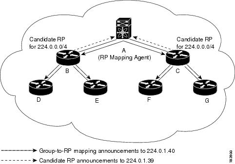
By default, routers are not enabled to listen or forward Auto-RP messages. You must enable the Auto-RP listening and forwarding feature so that the Auto-RP mechanism can dynamically inform routers in the PIM domain of the group-to-RP mapping.
Multiple RPs Configured in a PIM Domain
This section describes the election process rules when multiple RPs are configured in a PIM domain.
Anycast-RP
Anycast-RP has two implementations: one uses Multicast Source Discovery Protocol (MSDP) and the other is based on RFC 4610, Anycast-RP Using Protocol Independent Multicast (PIM). This section describes how to configure PIM Anycast-RP.
You can use PIM Anycast-RP to assign a group of routers, called the Anycast-RP set, to a single RP address that is configured on multiple routers. The set of routers that you configure as Anycast-RPs is called the Anycast-RP set. This method is the only RP method that supports more than one RP per multicast group, which allows you to load balance across all RPs in the set. The Anycast RP supports all multicast groups.
PIM register messages are sent to the closest RP, and PIM join-prune messages are sent in the direction of the closest RP as determined by the unicast routing protocols. If one of the RPs goes down, unicast routing ensures these messages will be sent in the direction of the next-closest RP.
You must configure PIM on the loopback interface that is used for the PIM Anycast RP.
PIM Register Messages
PIM register messages are unicast to the RP by designated routers (DRs) that are directly connected to multicast sources. The PIM register message has the following functions:
-
To notify the RP that a source is actively sending to a multicast group.
-
To deliver multicast packets sent by the source to the RP for delivery down the shared tree.
The DR continues to send PIM register messages to the RP until it receives a Register-Stop message from the RP. The RP sends a Register-Stop message in either of the following cases:
-
The RP has no receivers for the multicast group being transmitted.
-
The RP has joined the SPT to the source but has not started receiving traffic from the source.
You can use the ip pim register-source command to configure the IP source address of register messages when the IP source address of a register message is not a uniquely routed address to which the RP can send packets. This situation might occur if the source address is filtered so that the packets sent to it are not forwarded or if the source address is not unique to the network. In these cases, the replies sent from the RP to the source address will fail to reach the DR, resulting in Protocol Independent Multicast sparse mode (PIM-SM) protocol failures.
The following example shows how to configure the IP source address of the register message to the loopback 3 interface of a DR:
ip pim register-source loopback 3
Note | In Cisco NX-OS, PIM register messages are rate limited to avoid overwhelming the RP. |
You can filter PIM register messages by defining a routing policy.
Designated Routers
In PIM ASM mode, the software chooses a designated router (DR) from the routers on each network segment. The DR is responsible for forwarding multicast data for specified groups and sources on that segment.
The DR for each LAN segment is determined as described in the Hello messages.
In ASM mode, the DR is responsible for unicasting PIM register packets to the RP. When a DR receives an IGMP membership report from a directly connected receiver, the shortest path is formed to the RP, which may or may not go through the DR. The result is a shared tree that connects all sources transmitting on the same multicast group to all receivers of that group.
ASM Switchover from Shared Tree to Source Tree
Note | Cisco NX-OS puts the RPF interface into the OIF-list of the MRIB but not into the OIF-list of the MFIB. |
In ASM mode, the DR that is connected to a receiver switches over from the shared tree to the shortest-path tree (SPT) to a source unless you configure the PIM parameter to use shared trees only.
During the switchover, messages on the SPT and shared tree might overlap. These messages are different. The shared tree messages are propagated upstream toward the RP, while SPT messages go toward the source.
For information about SPT switchovers, see the “Last-Hop Switchover to the SPT" section in RFC 4601.
Administratively Scoped IP Multicast
The administratively scoped IP multicast method allows you to set boundaries on the delivery of multicast data. For more information, see RFC 2365.
You can configure an interface as a PIM boundary so that PIM messages are not sent out on that interface.
You can use the Auto-RP scope parameter to set a time-to-live (TTL) value.
PIM Graceful Restart
Protocol Independent Multicast (PIM) graceful restart is a multicast high availability (HA) enhancement that improves the convergence of multicast routes (mroutes) after a route processor (RP) switchover. In the event of an RP switchover, the PIM graceful restart feature utilizes the generation ID (GenID) value (defined in RFC 4601) as a mechanism to trigger adjacent PIM neighbors on an interface to send PIM join messages for all (*, G) and (S, G) states that use that interface as a reverse path forwarding (RPF) interface. This mechanism enables PIM neighbors to immediately reestablish those states on the newly active RP.
Generation IDs
A generation ID (GenID) is a randomly generated 32-bit value that is regenerated each time Protocol Independent Multicast (PIM) forwarding is started or restarted on an interface. In order to process the GenID value in PIM hello messages, PIM neighbors must be running Cisco software with an implementation of PIM that is compliant with RFC 4601.
Note | PIM neighbors that are not compliant with RFC 4601 and are unable to process GenID differences in PIM hello messages will ignore the GenIDs. |
PIM Graceful Restart Operations
This figure illustrates the operations that occur after a route processor (RP) switchover on devices that support the PIM graceful restart feature.
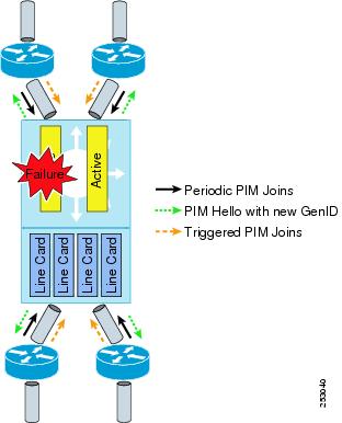
The PIM graceful restart operations are as follows:
- In steady state, PIM neighbors exchange periodic PIM hello messages.
- An active RP receives PIM joins periodically to refresh multicast route (mroute) states.
- When an active RP fails, the standby RP takes over to become the new active RP.
- The new active RP then modifies the generation ID (GenID) value and sends the new GenID in PIM hello messages to adjacent PIM neighbors.
- Adjacent PIM neighbors that receive PIM hello messages on an interface with a new GenID send PIM graceful restart for all (*, G) and (S, G) mroutes that use that interface as an RPF interface.
- Those mroute states are then immediately reestablished on the newly active RP.
PIM Graceful Restart and Multicast Traffic Flow
Multicast traffic flow on PIM neighbors is not affected if the multicast traffic detects support for PIM graceful restart PIM or PIM hello messages from a node with the failing RP within the default PIM hello hold-time interval. Multicast traffic flow on a failing RP is not affected if it is non-stop forwarding (NSF) capable.
Caution | The default PIM hello hold-time interval is 3.5 times the PIM hello period. Multicast high availability (HA) operations might not function as per design if you configure the PIM hello interval with a value lower than the default value of 30 seconds. |
High Availability
For information about high availability, see the Cisco Nexus 9000 Series NX-OS High Availability and Redundancy Guide.
Licensing Requirements for PIM
|
PIM requires an Enterprise Services license. For a complete explanation of the Cisco NX-OS licensing scheme and how to obtain and apply licenses, see the Cisco NX-OS Licensing Guide. |
Prerequisites for PIM
Guidelines and Limitations for PIM
PIM has the following guidelines and limitations:
-
For most Cisco Nexus devices, RPF failure traffic is dropped and sent to the CPU at a very low rate to trigger PIM asserts. For the Cisco Nexus 9000 Series switches, RPF failure traffic is always copied to the CPU in order to learn multicast sources.
-
For first-hop source detection in most Cisco Nexus devices, traffic coming from the first hop is detected based on the source subnet check, and multicast packets are copied to the CPU only if the source belongs to the local subnet. The Cisco Nexus 9000 Series switches cannot detect the local source, so multicast packets are sent to the supervisor to learn the local multicast source.
-
Cisco NX-OS PIM does not interoperate with any version of PIM dense mode or PIM sparse mode version 1.
-
Do not configure both Auto-RP and BSR protocols in the same network.
-
Configure candidate RP intervals to a minimum of 15 seconds.
-
If a device is configured with a BSR policy that should prevent it from being elected as the BSR, the device ignores the policy. This behavior results in the following undesirable conditions:
-
If a device receives a BSM that is permitted by the policy, the device, which incorrectly elected itself as the BSR, drops that BSM so that routers downstream fail to receive it. Downstream devices correctly filter the BSM from the incorrect BSR so that these devices do not receive RP information.
-
A BSM received by a BSR from a different device sends a new BSM but ensures that downstream devices do not receive the correct BSM.
-
-
Default values for the PIM hello interval are recommended and should not be modified.
-
Cisco NX-OS PIM does not support SSM on vPCs, but Cisco NX-OS PIM supports ASM on vPCs.
Note
PIM SSM commands might be visible in the software even though the Cisco Nexus 9000 Series switches do not support PIM SSM. If you try to configure PIM SSM, the configuration will not be activated.
-
Cisco Nexus 9000 Series switches do not support PIMv6 ASM, SSM, or BFD.
Default Settings
This table lists the default settings for PIM parameters.
Configuring PIM
You can configure PIM for each interface.
Note | Cisco NX-OS supports only PIM sparse mode version 2. In this publication, “PIM” refers to PIM sparse mode version 2. |
You can configure separate ranges of addresses in the PIM domain using the multicast distribution modes described in the table below.
- PIM Configuration Tasks
- Enabling the PIM Feature
- Configuring PIM Sparse Mode Parameters
- Configuring ASM
- Configuring RPF Routes for Multicast
- Configuring Route Maps to Control RP Information Distribution
- Configuring Message Filtering
- Restarting the PIM Processes
- Configuring BFD for PIM in VRF Mode
PIM Configuration Tasks
The following steps configure PIM.
-
Select the range of multicast groups that you want to configure in each multicast distribution mode.
-
Enable PIM.
-
Follow the configuration steps for the multicast distribution modes that you selected in Step 1.
-
Configure message filtering.
Note | The CLI commands used to configure PIM are as follows: |
Note | If you are familiar with the Cisco IOS CLI, be aware that the Cisco NX-OS commands for this feature might differ from the Cisco IOS commands that you would use. |
Enabling the PIM Feature
Before you can access the PIM commands, you must enable the PIM feature.
Ensure that you have installed the Enterprise Services license.
Configuring PIM Sparse Mode Parameters
You configure PIM sparse mode on every device interface that you want to participate in a sparse mode domain. You can configure the sparse mode parameters described in the table below.
|
Enables listening for and forwarding of Auto-RP messages. The default is disabled, which means that the router does not listen for or forward Auto-RP messages unless it is configured as a candidate RP or mapping agent. |
|||
|
Enables listening for and forwarding of BSR messages. The default is disabled, which means that the router does not listen for or forward BSR messages unless it is configured as a candidate RP or BSR candidate. |
|||
|
Configures the IPv4 register rate limit in packets per second. The range is from 1 to 65,535. The default is no limit. |
|||
|
Configures the IPv4 initial holddown period in seconds. This holddown period is the time it takes for the MRIB to come up initially. If you want faster convergence, enter a lower value. The range is from 90 to 210. Specify 0 to disable the holddown period. The default is 210. |
|||
|
Sets the designated router (DR) priority that is advertised in PIM hello messages on this interface. On a multi-access network with multiple PIM-enabled routers, the router with the highest DR priority is elected as the DR router. If the priorities match, the software elects the DR with the highest IP address. The DR originates PIM register messages for the directly connected multicast sources and sends PIM join messages toward the rendezvous point (RP) for directly connected receivers. Values range from 1 to 4294967295. The default is 1. |
|||
|
Designated router delay |
Delays participation in the designated router (DR) election by setting the DR priority that is advertised in PIM hello messages to 0 for a specified period. During this delay, no DR changes occur, and the current switch is given time to learn all of the multicast states on that interface. After the delay period expires, the correct DR priority is sent in the hello packets, which retriggers the DR election. Values range from 3 to 0xffff seconds. |
||
|
Enables an MD5 hash authentication key, or password, in PIM hello messages on the interface so that directly connected neighbors can authenticate each other. The PIM hello messages are IPsec encoded using the Authentication Header (AH) option. You can enter an unencrypted (cleartext) key or one of these values followed by a space and the MD5 authentication key: The authentication key can be up to 16 characters. The default is disabled. |
|||
|
Configures the interval at which hello messages are sent in milliseconds. The range is from 1000 to 18724286. The default is 30000.
|
|||
|
Enables the interface to be on the border of a PIM domain so that no bootstrap, candidate-RP, or Auto-RP messages are sent or received on the interface. The default is disabled. |
|||
|
Configures which PIM neighbors to become adjacent to based on a route-map policy1 where you can specify IP addresses to become adjacent to with the match ip address command. If the policy name does not exist or no IP addresses are configured in a policy, adjacency is established with all neighbors. The default is to become adjacent with all PIM neighbors.
|
|||
Configuring PIM Sparse Mode Parameters
Configuring ASM
Any Source Multicast (ASM) is a multicast distribution mode that requires the use of RPs to act as a shared root between sources and receivers of multicast data.
To configure ASM mode, you configure sparse mode and the RP selection method, where you indicate the distribution mode and assign the range of multicast groups.
- Configuring Static RPs
- Configuring BSRs
- Configuring Auto-RP
- Configuring a PIM Anycast-RP Set
- Configuring Shared Trees Only for ASM
Configuring Static RPs
You can configure an RP statically by configuring the RP address on every router that will participate in the PIM domain.
You can specify a route-map policy name that lists the group prefixes to use with the match ip multicast command.
The ip pim rp-address command has been enhanced with the following functionalities:
-
Added prefix-list method of configuration in addition to existing route-map method.
-
Added support for policy actions (route-map or prefix-list).
Note
Cisco NX-OS always uses the longest-match prefix to find the RP, so the behavior is the same irrespective of the position of the group prefix in the route map or in the prefix list.
The following example configuration produces the same output using Cisco NX-OS (231.1.1.0/24 is always denied irrespective of the sequence number):
ip prefix-list plist seq 10 deny 231.1.1.0/24 ip prefix-list plist seq 20 permit 231.1.0.0/16 ip prefix-list plist seq 10 permit 231.1.0.0/16 ip prefix-list plist seq 20 deny 231.1.1.0/24
Configuring Static RPs
Ensure that you have installed the Enterprise Services license and enabled PIM.
| Command or Action | Purpose | |
|---|---|---|
| Step 1 | configure terminal
Example: switch# configure terminal switch(config)# |
Enters global configuration mode. |
| Step 2 | ip pim rp-address
rp-address [group-list
ip-prefix |
route-map
policy-name]
Example: switch(config)# ip pim rp-address 192.0.2.33 group-list 224.0.0.0/9 |
Configures a PIM static RP address for a multicast group range. You can specify a route-map policy name that lists the group prefixes to use with the match ip multicast command. The mode is ASM. The default group range is ff00::0/8. The example configures PIM ASM mode for the specified group range. |
| Step 3 | show ip pim group-range
[ip-prefix |
vrf
vrf-name]
Example: switch(config)# show ip pim group-range | (Optional)
Displays PIM RP information, including BSR listen and forward states. |
| Step 4 | copy running-config startup-config
Example: switch(config)# copy running-config startup-config | (Optional)
Copies the running configuration to the startup configuration. |
Configuring BSRs
You configure BSRs by selecting candidate BSRs and RPs.
Caution | Do not configure both Auto-RP and BSR protocols in the same network. |
You can configure a candidate BSR with the arguments described in the table below.
|
Interface type and number used to derive the BSR source IP address used in bootstrap messages. |
|
|
Number of high order 1s used to form a mask that is ANDed with group address ranges of candidate RPs to form a hash value. The mask determines the number of consecutive addresses to assign across RPs with the same group range. This value ranges from 0 to 32 and has a default of 30. |
|
|
Priority assigned to this BSR. The software elects the BSR with the highest priority, or if the BSR priorities match, the software elects the BSR with the highest IP address. This value ranges from 0, the lowest priority, to 255 and has a default of 64. |
Configuring BSRs Candidate RP Arguments and Keywords
You can configure a candidate RP with the arguments and keywords described in this table.
|
Interface type and number used to derive the BSR source IP address used in bootstrap messages. |
|||
|
Multicast groups handled by this RP specified in a prefix format. |
|||
|
Number of seconds between sending candidate-RP messages. This value ranges from 1 to 65,535 and has a default of 60 seconds.
|
|||
|
Priority assigned to this RP. The software elects the RP with the highest priority for a range of groups or, if the priorities match, the highest IP address. (The highest priority is the lowest numerical value.) This value ranges from 0, the highest priority, to 255 and has a default of 192.
|
|||
|
Route-map policy name that defines the group prefixes where this feature is applied. |
 Tip | You should choose the candidate BSRs and candidate RPs that have good connectivity to all parts of the PIM domain. |
You can configure the same router to be both a BSR and a candidate RP. In a domain with many routers, you can select multiple candidate BSRs and RPs to automatically fail over to alternates if a BSR or an RP fails.
To configure candidate BSRs and RPs, follow these steps:
-
Configure whether each router in the PIM domain should listen for and forward BSR messages. A router configured as either a candidate RP or a candidate BSR will automatically listen for and forward all bootstrap router protocol messages, unless an interface is configured with the domain border feature.
-
Configure each candidate BSR and candidate RP as described in this section.
Configuring BSRs
Ensure that you have installed the Enterprise Services license and enabled PIM.
| Command or Action | Purpose | |||
|---|---|---|---|---|
| Step 1 | configure terminal
Example: switch# configure terminal switch(config)# |
Enters global configuration mode. | ||
| Step 2 | ip pim bsr {forward [listen] |
listen [forward]}
Example: switch(config)# ip pim bsr listen forward |
Configures listen and forward. Ensure that you have entered this command in each VRF on the remote PE. | ||
| Step 3 | ip pim
bsr
[bsr-candidate]
interface [hash-len
hash-length] [priority
priority]
Example: switch(config)# ip pim bsr-candidate ethernet 2/1 hash-len 24 |
Configures a candidate bootstrap router (BSR). The source IP address used in a bootstrap message is the IP address of the interface. The hash length ranges from 0 to 32 and has a default of 30. The priority ranges from 0 to 255 and has a default of 64. | ||
| Step 4 | ip [bsr]
rp-candidate
interface
group-list
ip-prefix
route-map
policy-name
priority
priority
interval
interval
Example: switch(config)# ip pim rp-candidate ethernet 2/1 group-list 239.0.0.0/24 | (Optional)
Configures a candidate RP for BSR. The priority ranges from 0, the highest priority, to 65,535 and has a default of 192. The interval ranges from 1 to 65,535 seconds and has a default of 60.
The example configures an ASM candidate RP. | ||
| Step 5 | show ip pim group-range
[ip-prefix |
vrf
vrf-name]
Example: switch(config)# show ip pim group-range | (Optional)
Displays PIM modes and group ranges. | ||
| Step 6 |
copy running-config
startup-config
Example: switch(config)# copy running-config startup-config | (Optional)
Copies the running configuration to the startup configuration. |
Configuring Auto-RP
You can configure Auto-RP by selecting candidate mapping agents and RPs. You can configure the same router to be both a mapping agent and a candidate RP.
Caution | Do not configure both Auto-RP and BSR protocols in the same network. |
You can configure an Auto-RP mapping agent with the arguments described in this table.
|
Interface type and number used to derive the IP address of the Auto-RP mapping agent used in bootstrap messages. |
|
|
Time-to-Live (TTL) value that represents the maximum number of hops that RP-Discovery messages are forwarded. This value can range from 1 to 255 and has a default of 32. |
If you configure multiple Auto-RP mapping agents, only one is elected as the mapping agent for the domain. The elected mapping agent ensures that all candidate RP messages are sent out. All mapping agents receive the candidate RP messages and advertise the same RP cache in their RP-discovery messages.
You can configure a candidate RP with the arguments and keywords described in this table.
|
Interface type and number used to derive the IP address of the candidate RP used in bootstrap messages. |
|||
|
Multicast groups handled by this RP. It is specified in a prefix format. |
|||
|
Time-to-Live (TTL) value that represents the maximum number of hops that RP-Discovery messages are forwarded. This value can range from 1 to 255 and has a default of 32. |
|||
|
Number of seconds between sending RP-Announce messages. This value can range from 1 to 65,535 and has a default of 60.
|
|||
|
Route-map policy name that defines the group prefixes where this feature is applied. |
Tip | You should choose mapping agents and candidate RPs that have good connectivity to all parts of the PIM domain. |
To configure Auto-RP mapping agents and candidate RPs, follow these steps:
-
For each router in the PIM domain, configure whether that router should listen for and forward Auto-RP messages. A router configured as either a candidate RP or an Auto-RP mapping agent will automatically listen for and forward all Auto-RP protocol messages, unless an interface is configured with the domain border feature.
-
Select the routers to act as mapping agents and candidate RPs.
-
Configure each mapping agent and candidate RP as described in this section.
Ensure that you have installed the Enterprise Services license and enabled PIM.
Configuring Auto RP
Ensure that you have installed the Enterprise Services license and enabled PIM.
| Command or Action | Purpose | |||
|---|---|---|---|---|
| Step 1 | configure terminal
Example: switch# configure terminal switch(config)# |
Enters global configuration mode. | ||
| Step 2 | ip pim {send-rp-discovery |
auto-rp
mapping-agent}
interface [scope
ttl]
Example: switch(config)# ip pim auto-rp mapping-agent ethernet 2/1 | Configures an Auto-RP mapping agent. The source IP address used in Auto-RP Discovery messages is the IP address of the interface. The default scope is 32. | ||
| Step 3 | ip pim {send-rp-announce |
auto-rp
rp-candidate}
interface {group-list
ip-prefix |
route_map
policy-name} [scope
ttl]
interval
interval]
Example: switch(config)# ip pim auto-rp rp-candidate ethernet 2/1 group-list 239.0.0.0/24 |
Configures an Auto-RP candidate RP. The default scope is 32. The default interval is 60 seconds. By default, the command creates an ASM candidate RP.
The example configures an ASM candidate RP. | ||
| Step 4 | show ip pim group-range
[ip-prefix |
vrf
vrf-name]
Example: switch(config)# show ip pim group-range | (Optional)
Displays PIM modes and group ranges. | ||
| Step 5 | copy running-config startup-config
Example: switch(config)# copy running-config startup-config | (Optional)
Copies the running configuration to the startup configuration. |
Configuring a PIM Anycast-RP Set
Configuring a PIM Anycast RP Set
Ensure that you have installed the Enterprise Services license and enabled PIM.
| Command or Action | Purpose | |
|---|---|---|
| Step 1 | configure terminal
Example: switch# configure terminal switch(config)# |
Enters global configuration mode. |
| Step 2 | interface loopback
number
Example: switch(config)# interface loopback 0 |
Configures an interface loopback. This example configures interface loopback 0. |
| Step 3 | ip address
ip-prefix
Example: switch(config-if)# ip address 192.0.2.3/32 |
Configures an IP address for this interface. This example configures an IP address for the Anycast-RP. |
| Step 4 | ip pim sparse-mode
Example: switch(config)# ip pim sparse-mode |
Enables PIM. |
| Step 5 |
ip pim anycast-rp
anycast-rp-address anycast-rp-peer-address
Example: switch(config)# ip pim anycast-rp 192.0.2.3 192.0.2.31 |
Configures a PIM Anycast-RP peer address for the specified Anycast-RP address. Each command with the same Anycast-RP address forms an Anycast-RP set. The IP addresses of RPs are used for communication with RPs in the set. |
| Step 6 | Repeat Step 5 using the same Anycast-RP address for each RP in the RP set (including the local router). |
— |
| Step 7 |
show ip
pim group-range [ip-prefix |
vrf
vrf-name]
Example: switch(config)# show ip pim group-range | (Optional)
Configures a PIM Anycast-RP peer address for the specified Anycast-RP address. Each command with the same Anycast-RP address forms an Anycast-RP set. The IP addresses of RPs are used for communication with RPs in the set. |
| Step 8 |
copy running-config
startup-config
Example: switch(config)# copy running-config startup-config | (Optional)
Copies the running configuration to the startup configuration. |
Configuring Shared Trees Only for ASM
You can configure shared trees only on the last-hop router for Any Source Multicast (ASM) groups, which means that the router never switches over from the shared tree to the SPT when a receiver joins an active group. You can specify a group range where the use of shared trees is to be enforced with the match ip multicast command. This option does not affect the normal operation of the router when a source tree join-prune message is received.
Note | The Cisco NX-OS software does not support the shared-tree feature on vPCs. For more information about vPCs, see the Cisco Nexus 9000 Series NX-OS Interfaces Configuration Guide. |
The default is disabled, which means that the software can switch over to source trees.
Note | In ASM mode, only the last-hop router switches from the shared tree to the SPT. |
Configuring Shared Trees Only for ASM
Ensure that you have installed the Enterprise Services license and enabled PIM.
| Command or Action | Purpose | |
|---|---|---|
| Step 1 | configure terminal
Example: switch# configure terminal switch(config)# |
Enters global configuration mode. |
| Step 2 | ip pim use-shared-tree-only group-list
policy-name
Example: switch(config)# ip pim use-shared-tree-only group-list my_group_policy | Builds only shared trees, which means that the software never switches over from the shared tree to the SPT. You specify a route-map policy name that lists the groups to use with the match ip multicast command. By default, the software triggers a PIM (S, G) join toward the source when it receives multicast packets for a source for which it has the (*, G) state. |
| Step 3 | show ip pim group-range
[ip-prefix |
vrf
vrf-name]
Example: switch(config)# show ip pim group-range | (Optional)
Displays PIM modes and group ranges. |
| Step 4 | copy running-config startup-config
Example: switch(config-if)# copy running-config startup-config | (Optional)
Copies the running configuration to the startup configuration. |
Configuring RPF Routes for Multicast
You can define reverse path forwarding (RPF) routes for multicast when you want multicast data to diverge from the unicast traffic path. You can define RPF routes for multicast on border routers to enable RPF to an external network.
Multicast routes are used not to directly forward traffic but to make RPF checks. RPF routes for multicast cannot be redistributed.
Note | IPv6 static multicast routes are not supported. |
Ensure that you have installed the Enterprise Services license and enabled PIM.
| Command or Action | Purpose | |
|---|---|---|
| Step 1 | configure terminal
Example: switch# configure terminal switch(config)# |
Enters global configuration mode. |
| Step 2 | ip mroute {ip-addr mask |
ip-prefix} {next-hop |
nh-prefix |
interface} [route-preference] [vrf
vrf-name]
Example: switch(config)# ip mroute 192.0.2.33/1 224.0.0.0/1 | Configures an RPF route for multicast for use in RPF calculations. Route preference values range from 1 to 255. The default preference is 1. |
| Step 3 | show ip static-route
[multicast] [vrf
vrf-name]
Example: switch(config)# show ip static-route multicast | (Optional) Displays configured static routes. |
| Step 4 | copy running-config startup-config
| (Optional)
Copies the running configuration to the startup configuration. |
Configuring Multicast Multipath
By default, the RPF interface for multicast is chosen automatically when multiple ECMP paths are available. Disabling the automatic selection allows you to specify a single RPF interface for multicast.
| Command or Action | Purpose | |
|---|---|---|
| Step 1 | configure terminal
Example: switch# configure terminal switch(config)# |
Enters global configuration mode. |
| Step 2 |
ip
multicast multipath {none |
s-g-hash
next-hop-based}
Example: switch(config)# ip multicast multipath none |
Configures multicast multipath using the following options:
|
| Step 3 | clear ip mroute
*
Example: switch(config)# clear ip mroute * |
Clears multipath routes and activates multicast multipath suppression. |
Configuring Route Maps to Control RP Information Distribution
You can configure route maps to help protect against some RP configuration errors and malicious attacks.
By configuring route maps, you can control distribution of RP information that is distributed throughout the network. You specify the BSRs or mapping agents to be listened to on each client router and the list of candidate RPs to be advertised (listened to) on each BSR and mapping agent to ensure that what is advertised is what you expect.
Ensure that you have installed the Enterprise Services license and enabled PIM.
Configuring Route Maps to Control RP Information Distribution
| Command or Action | Purpose | |||
|---|---|---|---|---|
| Step 1 | configure terminal
Example: switch# configure terminal switch(config)# |
Enters global configuration mode. | ||
| Step 2 | route-map
map-name [permit |
deny]
[sequence-number]
Example: switch(config)# route-map ASM_only permit 10 switch(config-route-map)# |
Enters route-map configuration mode. | ||
| Step 3 | match ip multicast
{rp
ip-address [rp-type
rp-type]} {{group-range {gadrr_start
to
gadrr_end} | {group ip-prefix}} {source
source-ip-address}
Example: switch(config-route-map)# match ip multicast group 224.0.0.0/4 rp 0.0.0.0/0 rp-type ASM |
Matches the group, RP, and RP type specified. You can specify the RP type (ASM). This configuration method requires the group and RP specified as shown in the example.
| ||
| Step 4 | show route-map
Example: switch(config-route-map)# show route-map | (Optional)
Displays configured route maps. | ||
| Step 5 | copy running-config startup-config
Example: switch(config-route-map)# copy running-config startup-config | (Optional)
Copies the running configuration to the startup configuration. |
Configuring Message Filtering
Note | Prefix matches in the rp-candidate-policy must be exact relative to what the c-rp is advertising. Subset matches are not possible. |
You can configure filtering of the PIM messages described in the table below.
|
Enables syslog messages that list the neighbor state changes to be generated. The default is disabled. |
|
|
Enables PIM register messages to be filtered based on a route-map policy2 where you can specify group or group and source addresses with the match ip multicast command. This policy applies to routers that act as an RP. The default is disabled, which means that the software does not filter PIM register messages. |
|
|
Enables BSR candidate RP messages to be filtered by the router based on a route-map policy where you can specify the RP and group addresses with the match ip command. This command can be used on routers that are eligible for BSR election. The default is no filtering of BSR messages. |
|
|
Enables BSR messages to be filtered by the BSR client routers based on a route-map policy where you can specify BSR source addresses with the match ip command. This command can be used on client routers that listen to BSR messages. The default is no filtering of BSR messages. |
|
|
Enables Auto-RP announce messages to be filtered by the Auto-RP mapping agents based on a route-map policy where you can specify the RP and group addresses with the match ip multicast command. This command can be used on a mapping agent. The default is no filtering of Auto-RP messages. |
|
|
Enables Auto-RP discover messages to be filtered by client routers based on a route-map policy where you can specify mapping agent source addresses with the match ip multicast command. This command can be used on client routers that listen to discover messages. The default is no filtering of Auto-RP messages. |
|
|
Enables join-prune messages to be filtered based on a route-map policy where you can specify group, group and source, or group and RP addresses with the match ip command. The default is no filtering of join-prune messages. |
|
Route maps as a filtering policy can be used (either permit or deny for each statement) for the following commands:
Route maps as containers can be used for the following commands, where the route-map action (permit or deny) is ignored:
Configuring Message Filtering (PIM)
Ensure that you have installed the Enterprise Services license and enabled PIM.
| Command or Action | Purpose | |
|---|---|---|
| Step 1 | configure terminal
Example: switch# configure terminal switch(config)# |
Enters global configuration mode. |
| Step 2 | ip pim log-neighbor-changes
Example: switch(config)# ip pim log-neighbor-changes | (Optional) Enables syslog messages that list the neighbor state changes to be generated. The default is disabled. |
| Step 3 | ip pim register-policy
policy-name
Example: switch(config)# ip pim register-policy my_register_policy | (Optional)
Enables PIM register messages to be filtered based on a route-map policy. You can specify group or group and source addresses with the match ip multicast command. |
| Step 4 | ip pim bsr rp-candidate-policy
policy-name
Example: switch(config)# ip pim bsr rp-candidate-policy my_bsr_rp_candidate_policy | (Optional)
Enables BSR candidate RP messages to be filtered by the router based on a route-map policy where you can specify the RP and group addresses with the match ip multicast command. This command can be used on routers that are eligible for BSR election. The default is no filtering of BSR messages. |
| Step 5 | ip pim bsr bsr-policy
policy-name
Example: switch(config)# ip pim bsr bsr-policy my_bsr_policy | (Optional)
Enables BSR messages to be filtered by the BSR client routers based on a route-map policy where you can specify BSR source addresses with the match ip multicast command. This command can be used on client routers that listen to BSR messages. The default is no filtering of BSR messages. |
| Step 6 |
ip pim auto-rp
rp-candidate-policy
policy-name
Example: switch(config)# ip pim auto-rp rp-candidate-policy my_auto_rp_candidate_policy | (Optional)
Enables Auto-RP announce messages to be filtered by the Auto-RP mapping agents based on a route-map policy where you can specify the RP and group addresses with the match ip multicast command. This command can be used on a mapping agent. The default is no filtering of Auto-RP messages. |
| Step 7 | ip pim auto-rp mapping-agent-policy
policy-name
Example: switch(config)# ip pim auto-rp mapping-agent-policy my_auto_rp_mapping_policy | (Optional)
Enables Auto-RP discover messages to be filtered by client routers based on a route-map policy where you can specify mapping agent source addresses with the match ip multicast command. This command can be used on client routers that listen to discover messages. The default is no filtering of Auto-RP messages. |
| Step 8 | interface
interface
Example: switch(config)# interface ethernet 2/1 switch(config-if)# |
Enters interface mode on the specified interface. |
| Step 9 | ip pim jp-policy
policy-name [in |
out]
Example: switch(config-if)# ip pim jp-policy my_jp_policy | (Optional)
Enables join-prune messages to be filtered based on a route-map policy where you can specify group, group and source, or group and RP addresses with the match ip multicast command. The default is no filtering of join-prune messages. |
| Step 10 | show run pim
Example: switch(config-if)# show run pim | (Optional)
Displays PIM configuration commands. |
| Step 11 | copy running-config startup-config
Example: switch(config-if)# copy running-config startup-config | (Optional)
Copies the running configuration to the startup configuration. |
Restarting the PIM Processes
You can restart the PIM processes and optionally flush all routes. By default, routes are not flushed.
When routes are flushed, they are removed from the Multicast Routing Information Base (MRIB) and the Multicast Forwarding Information Base (MFIB).
Restarting the PIM Process
Ensure that you have installed the Enterprise Services license and enabled PIM.
| Command or Action | Purpose | |
|---|---|---|
| Step 1 | restart pim
Example: switch# restart pim |
Restarts the PIM process. |
| Step 2 | configure terminal
Example: switch# configure terminal switch(config)# |
Enters global configuration mode. |
| Step 3 | ip pim flush-routes
Example: switch(config)# ip pim flush-routes | Removes routes when the PIM process is restarted. By default, routes are not flushed. |
| Step 4 | show running-configuration pim
Example: switch(config)# show running-configuration pim | (Optional)
Displays the PIM running-configuration information, including the flush-routes command. |
| Step 5 | copy running-config startup-config
Example: switch(config)# copy running-config startup-config | (Optional)
Copies the running configuration to the startup configuration. |
Configuring BFD for PIM in VRF Mode
Note | You can configure Bidirectional Forwarding Detection (BFD) for PIM by either VRF or interface. |
Ensure that you have installed the Enterprise Services license, enabled PIM, and enabled BFD.
| Command or Action | Purpose | |||
|---|---|---|---|---|
| Step 1 | configure terminal
Example: switch# configure terminal switch(config)# | |||
| Step 2 | vrf context
vrf-name
Example: switch# vrf context test switch(config-vrf)# | |||
| Step 3 | ip pim bfd
Example: switch(config-vrf)# ip pim bfd |
Enables BFD on the specified VRF.
|
Configuring BFD for PIM in Interface Mode
Ensure that you have installed the Enterprise Services license, enabled PIM, and enabled BFD.
| Command or Action | Purpose | |
|---|---|---|
| Step 1 | configure terminal
Example: switch# configure terminal switch(config)# | |
| Step 2 | interface
interface-type
Example: switch(config)# interface ethernet 7/40 switch(config-if)# |
Enters interface configuration mode. |
| Step 3 | ip pim bfd instance
Example: switch(config-if)# ip pim bfd instance |
Enables BFD on the specified interfaces. You can enable or disable BFD on PIM interfaces irrespective of whether BFD is enabled on the VRF. |
| Step 4 | show running-configuration pim
Example: switch(config-if)# show running-configuration pim | (Optional)
Displays the PIM running-configuration information. |
| Step 5 | copy running-config startup-config
Example: switch(config-if)# copy running-config startup-config | (Optional)
Copies the running configuration to the startup configuration. |
Verifying the PIM Configuration
To display the PIM configuration information, perform one of the following tasks:
|
Command |
|
|---|---|
|
Displays the designated forwarder (DF) information for each RP by interface. |
|
|
Displays the learned or configured group ranges and modes. For similar information, see the show ip pim rp command. |
|
|
Displays all the interfaces in the outgoing interface (OIF) list. |
|
|
show ip pim route [source group | group [source]][vrf vrf-name] |
Displays information for each multicast route, including interfaces on which a PIM join for that (S, G) has been received. |
|
Displays rendezvous points (RPs) known to the software, how they were learned, and their group ranges. For similar information, see the show ip pim group-range command. |
|
|
Displays the bootstrap router (BSR) RP hash information. For information about the RP hash, see RFC 5059. |
|
Displaying Statistics
You can display and clear PIM statistics by using the commands in this section.
Displaying PIM Statistics
You can display the PIM statistics and memory usage using these commands.
|
Command |
|
|---|---|
|
Displays policy statistics for register, RP, and join-prune message policies. |
|
Clearing PIM Statistics
You can clear the PIM statistics using these commands.
|
Command |
|
|---|---|
|
Clears policy counters for register, RP, and join-prune message policies. |
|
Configuration Examples for PIM
This section describes how to configure PIM using different data distribution modes and RP selection methods.
- BSR Configuration Example
- PIM Anycast RP Configuration Example
- Prefix-Based and Route-Map-Based Configurations
BSR Configuration Example
To configure PIM in ASM mode using the BSR mechanism, follow these steps for each router in the PIM domain:
-
Configure PIM sparse mode parameters on the interfaces that you want to participate in the domain. We recommend that you enable PIM on all interfaces.
switch# configure terminal switch(config)# interface ethernet 2/1 switch(config-if)# ip pim sparse-mode
-
Configure whether that router should listen and forward BSR messages.
switch# configure terminal switch(config)# ip pim bsr forward listen
-
Configure the BSR parameters for each router that you want to act as a BSR.
switch# configure terminal switch(config)# ip pim bsr-candidate ethernet 2/1 hash-len 30
-
Configure the RP parameters for each router that you want to act as a candidate RP.
switch# configure terminal switch(config)# ip pim rp-candidate ethernet 2/1 group-list 239.0.0.0/24
-
Configure message filtering.
switch# configure terminal switch(config)# ip pim log-neighbor-changes
The following example shows how to configure PIM ASM mode using the BSR mechanism and how to configure the BSR and RP on the same router:
configure terminal interface ethernet 2/1 ip pim sparse-mode exit ip pim bsr forward listen ip pim bsr-candidate ethernet 2/1 hash-len 30 ip pim rp-candidate ethernet 2/1 group-list 239.0.0.0/24 ip pim log-neighbor-changes
PIM Anycast RP Configuration Example
To configure ASM mode using the PIM Anycast-RP method, follow these steps for each router in the PIM domain:
-
Configure PIM sparse mode parameters on the interfaces that you want to participate in the domain. We recommend that you enable PIM on all interfaces.
switch# configure terminal switch(config)# interface ethernet 2/1 switch(config-if)# ip pim sparse-mode
-
Configure the RP address that you configure on all routers in the Anycast-RP set.
switch# configure terminal switch(config)# interface loopback 0 switch(config-if)# ip address 192.0.2.3/32
-
Configure a loopback with an address to use in communication between routers in the Anycast-RP set for each router that you want to be in the Anycast-RP set.
switch# configure terminal switch(config)# interface loopback 1 switch(config-if)# ip address 192.0.2.31/32
-
Configure the Anycast-RP parameters and repeat with the IP address of each Anycast-RP for each router that you want to be in the Anycast-RP set. This example shows two Anycast-RPs.
switch# configure terminal switch(config)# ip pim anycast-rp 192.0.2.3 193.0.2.31 switch(config)# ip pim anycast-rp 192.0.2.3 193.0.2.32
-
Configure message filtering.
switch# configure terminal switch(config)# ip pim log-neighbor-changes
The following example shows how to configure PIM ASM mode using two Anycast-RPs:
configure terminal
interface ethernet 2/1
ip pim sparse-mode
exit
interface loopback 0
ip address 192.0.2.3/32
exit
ip pim anycast-rp 192.0.2.3 192.0.2.31
ip pim anycast-rp 192.0.2.3 192.0.2.32
ip pim log-neighbor-changes
Prefix-Based and Route-Map-Based Configurations
ip prefix-list plist11 seq 10 deny 231.129.128.0/17
ip prefix-list plist11 seq 20 deny 231.129.0.0/16
ip prefix-list plist11 seq 30 deny 231.128.0.0/9
ip prefix-list plist11 seq 40 permit 231.0.0.0/8

ip prefix-list plist22 seq 10 deny 231.129.128.0/17
ip prefix-list plist22 seq 20 deny 231.129.0.0/16
ip prefix-list plist22 seq 30 permit 231.128.0.0/9
ip prefix-list plist22 seq 40 deny 231.0.0.0/8

ip prefix-list plist33 seq 10 deny 231.129.128.0/17
ip prefix-list plist33 seq 20 permit 231.129.0.0/16
ip prefix-list plist33 seq 30 deny 231.128.0.0/9
ip prefix-list plist33 seq 40 deny 231.0.0.0/8

ip pim rp-address 172.21.0.11 prefix-list plist11
ip pim rp-address 172.21.0.22 prefix-list plist22
ip pim rp-address 172.21.0.33 prefix-list plist33
route-map rmap11 deny 10
 match ip multicast group 231.129.128.0/17
route-map rmap11 deny 20
 match ip multicast group 231.129.0.0/16
route-map rmap11 deny 30
 match ip multicast group 231.128.0.0/9
route-map rmap11 permit 40
 match ip multicast group 231.0.0.0/8

route-map rmap22 deny 10
 match ip multicast group 231.129.128.0/17
route-map rmap22 deny 20
 match ip multicast group 231.129.0.0/16
route-map rmap22 permit 30
 match ip multicast group 231.128.0.0/9
route-map rmap22 deny 40
 match ip multicast group 231.0.0.0/8

route-map rmap33 deny 10
 match ip multicast group 231.129.128.0/17
route-map rmap33 permit 20
 match ip multicast group 231.129.0.0/16
route-map rmap33 deny 30
 match ip multicast group 231.128.0.0/9
route-map rmap33 deny 40
 match ip multicast group 231.0.0.0/8

ip pim rp-address 172.21.0.11 route-map rmap11
ip pim rp-address 172.21.0.22 route-map rmap22
ip pim rp-address 172.21.0.33 route-map rmap33
Output
dc3rtg-d2(config-if)# show ip pim rp
PIM RP Status Information for VRF "default"
BSR disabled
Auto-RP disabled
BSR RP Candidate policy: None
BSR RP policy: None
Auto-RP Announce policy: None
Auto-RP Discovery policy: None

RP: 172.21.0.11, (0), uptime: 00:12:36, expires: never,
  priority: 0, RP-source: (local), group-map: rmap11, group ranges:
      231.0.0.0/8  231.128.0.0/9 (deny)
      231.129.0.0/16 (deny) 231.129.128.0/17 (deny)
RP: 172.21.0.22, (0), uptime: 00:12:36, expires: never,
  priority: 0, RP-source: (local), group-map: rmap22, group ranges:
      231.0.0.0/8 (deny) 231.128.0.0/9
      231.129.0.0/16 (deny) 231.129.128.0/17 (deny)
RP: 172.21.0.33, (0), uptime: 00:12:36, expires: never,
  priority: 0, RP-source: (local), group-map: rmap33, group ranges:
      231.0.0.0/8 (deny) 231.128.0.0/9 (deny)
      231.129.0.0/16  231.129.128.0/17 (deny)

dc3rtg-d2(config-if)# show ip mroute
IP Multicast Routing Table for VRF "default"

(*, 231.1.1.1/32), uptime: 00:07:20, igmp pim ip
  Incoming interface: Ethernet2/1, RPF nbr: 10.165.20.1
  Outgoing interface list: (count: 1)
    loopback1, uptime: 00:07:20, igmp

(*, 231.128.1.1/32), uptime: 00:14:27, igmp pim ip
  Incoming interface: Ethernet2/1, RPF nbr: 10.165.20.1
  Outgoing interface list: (count: 1)
    loopback1, uptime: 00:14:27, igmp

(*, 231.129.1.1/32), uptime: 00:14:25, igmp pim ip
  Incoming interface: Ethernet2/1, RPF nbr: 10.165.20.1
  Outgoing interface list: (count: 1)
    loopback1, uptime: 00:14:25, igmp

(*, 231.129.128.1/32), uptime: 00:14:26, igmp pim ip
  Incoming interface: Null, RPF nbr: 10.0.0.1
  Outgoing interface list: (count: 1)
    loopback1, uptime: 00:14:26, igmp

(*, 232.0.0.0/8), uptime: 1d20h, pim ip
  Incoming interface: Null, RPF nbr: 10.0.0.1
  Outgoing interface list: (count: 0)

dc3rtg-d2(config-if)# show ip pim group-range
PIM Group-Range Configuration for VRF "default"
Group-range        Mode      RP-address       Shared-tree-only range
232.0.0.0/8        ASM       -                -
231.0.0.0/8        ASM       172.21.0.11      -
231.128.0.0/9      ASM       172.21.0.22      -
231.129.0.0/16     ASM       172.21.0.33      -
231.129.128.0/17   Unknown   -                -
Related Documents
Cisco Nexus 9000 Series NX-OS Unicast Routing Configuration Guide |
Standards
No new or modified standards are supported by this feature, and support for existing standards has not been modified by this feature. |
MIBs
|
MIBs related to PIM |
To locate and download supported MIBs, go to the following URL: ftp://ftp.cisco.com/pub/mibs/supportlists/nexus9000/Nexus9000MIBSupportList.html |
 Feedback