Cisco Nexus 9396PX NX-OS Mode Switch Hardware Installation Guide
Bias-Free Language
The documentation set for this product strives to use bias-free language. For the purposes of this documentation set, bias-free is defined as language that does not imply discrimination based on age, disability, gender, racial identity, ethnic identity, sexual orientation, socioeconomic status, and intersectionality. Exceptions may be present in the documentation due to language that is hardcoded in the user interfaces of the product software, language used based on RFP documentation, or language that is used by a referenced third-party product. Learn more about how Cisco is using Inclusive Language.
- Updated:
- June 3, 2015
Chapter: Overview
Contents
Overview
Overview
The Cisco Nexus 9396PX switch (N9K-C9396PX) is a 2-RU, fixed-port switch designed for Top-of-Rack (ToR), Middle-of-Rack (MoR), and End-of-Rack (EoR) deployment in data centers. This switch has 48 fixed 1- and 10-Gigabit Ethernet downlink ports and a choice of 4-, 6-, or 12-port uplink modules. The chassis for this switch includes the following user-replaceable components:
- Uplink modules (one of either of the following for uplink ports)
-
Fan modules (three—two for operations and one for redundancy [2+1]) with the following airflow choices:
-
Power supplies (two—one for operations and one for redundancy [1+1]) with the following airflow choices:
-
650-W port-side exhaust AC power supply with blue coloring (N9K-PAC-650W)
-
650-W port-side intake AC power supply with burgundy coloring (N9K-PAC-650W-B)
-
930-W port-side-intake DC power supply with burgundy latch handle (UCSC-PSU-930WDC)

Note
You can use 650-W AC power supplies and 930-W DC power supplies interchangeably so long as they have the same direction of airflow (if DC power supplies are used, all of the fan and power supply modules must have port-side intake airflow).
-
This switch supports connections to the following Fabric Extenders (FEXs):
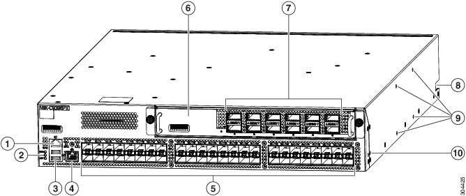
The following figure shows the hardware features seen from the port side of the chassis.
|
1 |
Console port (RS232 port) |
6 |
M4PC, M6PQ, or M12PQ uplink module (M12PQ uplink module shown). |
||
|
2 |
Chassis LEDs |
7 |
4-port 100-Gigabit Ethernet CFP2 optical ports, or 6- or 12-port 40-Gigabit Ethernet Quad Small Form-Factor Plugable (QSFP+) optical ports for connections to other devices (12-port uplink module shown) |
||
|
3 |
Two USB ports used for saving or copying functions
|
8 |
Notch in both sides of the chassis for locking the power supply end of the chassis to the bottom-support rails |
||
|
4 |
Out-of-band management port (RJ-45 port) |
9 |
Screw holes (4) for attaching a center-mount rack bracket for two-post racks (one bracket for each of two sides) |
||
|
5 |
48 1- and 10-Gigabit Ethernet Small Form-Factor Plugable (SFP+) optical ports (supporting 1-Gigabit and 10-Gigabit speeds) to switches or Fabric Extenders (FEXs) |
10 |
Screw holes (2) for attaching a front-mount bracket for four-post racks (one bracket on each of two sides) |
You can use the 1- and 10-Gigabit ports to connect this switch to up to 48 devices or to FEXs, which can be connected to additional servers (for the number of FEXs that can be supported, see the release notes for the NX-OS software that you are using). You can connect any of the following FEXs to the downlink ports:
-
Cisco Nexus B22DELL-P FEX
-
Cisco Nexus B22HP-P FEX
-
Cisco Nexus 2248PQ-10GE
-
Cisco Nexus 2248TP FEX
-
Cisco Nexus 2248TP-E FEX
-
Cisco Nexus 2232PP FEX
-
Cisco Nexus 2232TM FEX
For installation information on the Cisco Nexus 2000 Series FEXs, see the Cisco Nexus 2000 Series Hardware Installation Guide. For information on the Cisco Nexus B22-HP FEX, see the Cisco Nexus B22 Fabric Extender for HP Getting Started Guide.
To determine which transceivers, adapters, and cables are supported by this switch, see the Cisco Nexus 9000 Series (Fixed 9300) at http://www.cisco.com/c/en/us/support/interfaces-modules/transceiver-modules/products-device-support-tables-list.html.
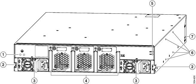
The following figure shows the hardware features seen from the fan side of the chassis.
|
1 |
Screw holes (2) for attaching the grounding lug. |
5 |
Chassis LEDs are as follows: |
||
|
2 |
Notch in both sides of the chassis for locking the fan end of the chassis to the bottom-support rails. |
6 |
Screw holes (4) for attaching a center-mount rack bracket for two-post racks (one bracket for each of two sides). |
||
|
3 |
Two power supply modules (AC power supply shown) Power supply slots are numbered 1 on the left and 2 on the right (as seen when looking at the power supplies). |
7 |
Screw holes (2) for attaching a front-mount bracket for four-post racks (one bracket on each of two sides). |
||
|
4 |
Three fan modules (two used for operations and one used for redundancy) of the following types:
Fan slots are numbered 1 (leftmost slot) to 3 (rightmost slot). |