Cisco Nexus 6000 Series NX-OS Interfaces Configuration Guide, Release 7.x
Bias-Free Language
The documentation set for this product strives to use bias-free language. For the purposes of this documentation set, bias-free is defined as language that does not imply discrimination based on age, disability, gender, racial identity, ethnic identity, sexual orientation, socioeconomic status, and intersectionality. Exceptions may be present in the documentation due to language that is hardcoded in the user interfaces of the product software, language used based on RFP documentation, or language that is used by a referenced third-party product. Learn more about how Cisco is using Inclusive Language.
- Updated:
- January 29, 2014
Chapter: Configuring Q-in-Q VLAN Tunnels
Configuring Q-in-Q VLAN Tunnels
This chapter contains the following sections:
- Information About Q-in-Q VLAN Tunnels
- Licensing Requirements for Q-in-Q Tunnels
- Guidelines and Limitations for Q-in-Q VLAN Tunnels
- Verifying the Q-in-Q Configuration
- Configuration Examples for Q-in-Q Tunneling
Information About Q-in-Q VLAN Tunnels
A Q-in-Q VLAN tunnel enables a service provider to segregate the traffic of different customers in their infrastructure, while still giving the customer a full range of VLANs for their internal use by adding a second 802.1Q tag to an already tagged frame.
Q-in-Q Tunneling
Business customers of service providers often have specific requirements for VLAN IDs and the number of VLANs to be supported. The VLAN ranges required by different customers in the same service-provider network might overlap, and the traffic of customers through the infrastructure might be mixed. Assigning a unique range of VLAN IDs to each customer would restrict customer configurations and could easily exceed the VLAN limit of 4096 of the 802.1Q specification.
 Note | Q-in-Q is supported on port channels and virtual port channels (vPCs). To configure a port channel as an asymmetrical link, all ports in the port channel must have the same tunneling configuration. |
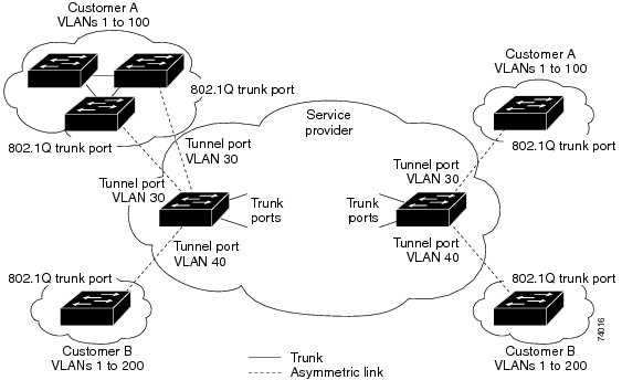
Using the 802.1Q tunneling feature, service providers can use a single VLAN to support customers who have multiple VLANs. Customer VLAN IDs are preserved and the traffic from different customers is segregated within the service-provider infrastructure even when they appear to be on the same VLAN.
The 802.1Q tunneling expands the VLAN space by using a VLAN-in-VLAN hierarchy and tagging the tagged packets. A port configured to support 802.1Q tunneling is called a tunnel port. When you configure tunneling, you assign a tunnel port to a VLAN that is dedicated to tunneling. Each customer requires a separate VLAN, but that VLAN supports all of the customer’s VLANs.
Customer traffic that is tagged in the normal way with appropriate VLAN IDs come from an 802.1Q trunk port on the customer device and into a tunnel port on the service-provider edge switch. The link between the customer device and the edge switch is an asymmetric link because one end is configured as an 802.1Q trunk port and the other end is configured as a tunnel port. You assign the tunnel port interface to an access VLAN ID that is unique to each customer.
Note | Selective Q-in-Q tunneling is not supported. All frames that enter the tunnel port are subject to Q-in-Q tagging. |
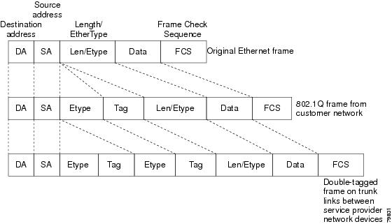
Packets that enter the tunnel port on the service-provider edge switch, which are already 802.1Q-tagged with the appropriate VLAN IDs, are encapsulated with another layer of an 802.1Q tag that contains a VLAN ID that is unique to the customer. The original 802.1Q tag from the customer is preserved in the encapsulated packet. Therefore, packets that enter the service-provider infrastructure are double-tagged.
The outer tag contains the customer’s access VLAN ID (as assigned by the service provider), and the inner VLAN ID is the VLAN of the incoming traffic (as assigned by the customer). This double tagging is called tag stacking, Double-Q, or Q-in-Q as shown in the following figure.
By using this method, the VLAN ID space of the outer tag is independent of the VLAN ID space of the inner tag. A single outer VLAN ID can represent the entire VLAN ID space for an individual customer. This technique allows the customer’s Layer 2 network to extend across the service provider network, potentially creating a virtual LAN infrastructure over multiple sites.
Note | Hierarchical tagging, or multi-level dot1q tagging Q-in-Q, is not supported. |
Native VLAN Hazard
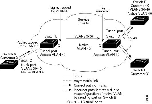
When configuring 802.1Q tunneling on an edge switch, you must use 802.1Q trunk ports for sending out packets into the service-provider network. However, packets that go through the core of the service-provider network might be carried through 802.1Q trunks, ISL trunks, or nontrunking links. When 802.1Q trunks are used in these core switches, the native VLANs of the 802.1Q trunks must not match any native VLAN of the dot1q-tunnel port on the same switch because traffic on the native VLAN is not tagged on the 802.1Q transmitting trunk port.
In the following figure, VLAN 40 is configured as the native VLAN for the 802.1Q trunk port from Customer X at the ingress edge switch in the service-provider network (Switch B). Switch A of Customer X sends a tagged packet on VLAN 30 to the ingress tunnel port of Switch B in the service-provider network that belongs to access VLAN 40. Because the access VLAN of the tunnel port (VLAN 40) is the same as the native VLAN of the edge-switch trunk port (VLAN 40), the 802.1Q tag is not added to tagged packets that are received from the tunnel port. The packet carries only the VLAN 30 tag through the service-provider network to the trunk port of the egress-edge switch (Switch C) and is misdirected through the egress switch tunnel port to Customer Y.
These are a couple ways to solve the native VLAN problem:
- Configure the edge switch so that all packets going out an 802.1Q trunk, including the native VLAN, are tagged by using the vlan dot1q tag native command. If the switch is configured to tag native VLAN packets on all 802.1Q trunks, the switch accepts untagged packets but sends only tagged packets.
Note | The vlan dot1q tag native command is a global command that affects the tagging behavior on all trunk ports. |
Licensing Requirements for Q-in-Q Tunnels
The following table shows the licensing requirements for this feature:
| Product | License Requirement |
|---|---|
|
Cisco NX-OS |
802.1Q-in-Q VLAN tunneling require no license. Any feature not included in a license package is bundled with the Cisco NX-OS system images and is provided at no extra charge to you. For a complete explanation of the Cisco NX-OS licensing scheme, see the Cisco NX-OS Licensing Guide. |
Guidelines and Limitations for Q-in-Q VLAN Tunnels
Q-in-Q tunnels have the following configuration guidelines and limitations:
-
Switches in the service-provider network must be configured to handle the increase in MTU size due to Q-in-Q tagging.
-
MAC address learning for Q-in-Q tagged packets is based on the outer VLAN (Service Provider VLAN) tag. Packet forwarding issues might occur in deployments where a single MAC address is used across multiple inner (customer) VLANs.
-
Layer 3 and higher parameters cannot be identified in tunnel traffic (for example, Layer 3 destination and source addresses). Tunneled traffic cannot be routed.
-
Cisco Nexus devices can provide only MAC-layer ACL/QoS for tunnel traffic (VLAN IDs and src/dest MAC addresses).
-
You should use MAC address-based frame distribution.
-
Asymmetrical links do not support the Dynamic Trunking Protocol (DTP) because only one port on the link is a trunk. You must configure the 802.1Q trunk port on an asymmetrical link to trunk unconditionally.
-
You cannot configure the 802.1Q tunneling feature on ports that are configured to support private VLANs. Private VLANs are not required in these deployments.
-
Control Plane Policing (CoPP) is not supported.
-
You should enter the vlan dot1Q tag native command on the trunk side of the service provider ports (not the dot1q-tunnel port) to prevent any native VLAN mis-configurations.
-
You must manually configure the 802.1Q interfaces to be edge ports.
-
Dot1x tunneling is not supported.
-
You should perform an EPLD upgrade to newer versions in order for EtherType configuration to take effect on some Cisco Nexus devices.
-
STP is not be supported on inner VLAN.
-
No loop detection mechanism in the fabric.
-
Cisco Discovery Protocol (CDP) is incompatible with Q-in-Q. When a port is configured as an 802.1Q tunnel port, CDP must be disabled on the interface.
-
Quality of Service (QoS) cannot detect the received Class of Service (CoS) value in the 802.1Q 2-byte Tag Control Information field.
-
On an asymmetrical link, CDP reports a native VLAN mismatch if the VLAN of the tunnel port does not match the native VLAN of the .1Q trunk. The .1Q tunnel feature does not require that the VLANs match. Ignore the messages in this configuration.
-
In break-out configurations, all the ports in the same forwarding instance are configured with dot1qtunnel on an all/none basis. Ports lacking a dot1q tunnel configuration are brought down and err-disabled.
-
All ports on a FEX are configured as all/none in dot1qtunnel. Those missing dot1qtunnel stay error disabled.
-
All ports in same forwarding instance (4x 10GEs or 1x QSFP+) are required to be in dot1q tunnel mode.
-
All members of a port-channel propagate runtime configurations to other ports belonging to same fwm block.
-
Configuring Dot1qtunnel on a FEX HIF on one switch of an AA FEX topology, resets that FEX on the other switch before bringing it online.
-
Q-in-Q VLAN tunnels are supported only on Cisco Nexus 6000 and Cisco Nexus 5600 platforms.
Creating an 802.1Q Tunnel Port
You must first configure the interface as a switchport.
This example shows how to create an 802.1Q tunnel port:
switch# configure terminal
switch(config)# interface ethernet 7/1
switch(config-if)# switchport
switch(config-if)# switchport mode dot1q-tunnel
switch(config-if)# exit
switch(config)# exit
switch# show dot1q-tunnel
Changing the EtherType for Q-in-Q
Note | You must set the EtherType only on the egress trunk interface that carries double tagged frames (the trunk interface that connects the service providers). If you change the EtherType on one side of the trunk, you must set the same value on the other end of the trunk (symmetrical configuration). This is an optional configuration. |
 Caution | The EtherType value you set affect all the tagged packets that go out on the interface (not just Q-in-Q packets). |
This example show how to create an 802.1Q tunnel port:
switch# configure terminal
switch(config)# interface ethernet 7/1
switch(config-if)# switchport
switch(config-if)# switchport dot1q ethertype 0x9100
switch(config-if)# exit
switch(config)# exit
switch# show dot1q-tunnel
Verifying the Q-in-Q Configuration
To display Q-in-Q tunnel configuration information, perform one of the following tasks:
| Command | Purpose |
|---|---|
|
show dot1q-tunnel [interface if-range] |
Displays a range of interfaces or all interfaces that are in dot1q-tunnel mode. |
Configuration Examples for Q-in-Q Tunneling
This example shows a service provider switch that is configured to process Q-in-Q for traffic coming in on Ethernet 7/1. The customer is allocated VLAN 10 (outer VLAN tag).
switch# configure terminal
Enter configuration commands, one per line. End with CNTL/Z.
switch(config)# vlan 10
switch(config-vlan)# no shutdown
switch(config-vlan)# no ip igmp snooping
switch(config-vlan)# exit
switch(config)# interface ethernet 7/1
switch(config-if)# switchport
switch(config-if)# switchport mode dot1q-tunnel
switch(config-if)# switchport access vlan 10
switch(config-if)# spanning-tree port type edge

switch(config-if)# no shutdown
switch(config-if)# exit
switch(config)# exit
switch#
 Feedback