Cisco Nexus 1010 Software Installation and Upgrade Guide, Release 4.2(1)SP1(4a)
Bias-Free Language
The documentation set for this product strives to use bias-free language. For the purposes of this documentation set, bias-free is defined as language that does not imply discrimination based on age, disability, gender, racial identity, ethnic identity, sexual orientation, socioeconomic status, and intersectionality. Exceptions may be present in the documentation due to language that is hardcoded in the user interfaces of the product software, language used based on RFP documentation, or language that is used by a referenced third-party product. Learn more about how Cisco is using Inclusive Language.
- Updated:
- May 10, 2012
Chapter: Installing Cisco Nexus 1010
- Information About Software Install
- Prerequisites
- Guidelines and Limitations
- CIMC And BIOS Information
- Gathering Information About the Management Software
Cisco Nexus 1010 Software Installation
This chapter describes how to install the Cisco Nexus 1010 and Cisco Nexus 1010-X software, and includes the following sections:
•![]() Information About Software Install
Information About Software Install
•![]() Gathering Information About the Management Software
Gathering Information About the Management Software
•![]() Setting up the Primary Cisco Nexus 1010 or Cisco Nexus 1010-X
Setting up the Primary Cisco Nexus 1010 or Cisco Nexus 1010-X
•![]() Setting up the Secondary Cisco Nexus 1010 or Cisco Nexus 1010-X
Setting up the Secondary Cisco Nexus 1010 or Cisco Nexus 1010-X
•![]() Example for Network Uplink Configuration
Example for Network Uplink Configuration
•![]() Verifying the Cisco Nexus 1010 Configuration
Verifying the Cisco Nexus 1010 Configuration
•![]() Getting Started With Cisco Nexus 1010
Getting Started With Cisco Nexus 1010
•![]() Feature History for Software Installation
Feature History for Software Installation

Note ![]() For information about upgrading Cisco Nexus 1000V software on a VSB, see the Cisco Nexus 1000V Software Installation and Upgrade Guide, Release 4.2(1)SV1(5.1).
For information about upgrading Cisco Nexus 1000V software on a VSB, see the Cisco Nexus 1000V Software Installation and Upgrade Guide, Release 4.2(1)SV1(5.1).
For an overview of the Cisco Nexus 1010 product family and procedures for configuring the software after it is installed, see the Cisco Nexus 1010 Software Configuration Guide, Release 4.2(1)SP1(4).
Information About Software Install
Cisco Nexus 1010 and Cisco Nexus 1010-X software is pre installed as an ISO image. Use this procedure to install the Cisco Nexus 1010 or Cisco Nexus 1010-X software. The installation involves the following steps:
Step 1 ![]() Verify that you have the correct Cisco Integrated Management Controller (CIMC) software installed. See CIMC And BIOS Information.
Verify that you have the correct Cisco Integrated Management Controller (CIMC) software installed. See CIMC And BIOS Information.
Step 2 ![]() Gather information about Management Software. See Gathering Information About the Management Software.
Gather information about Management Software. See Gathering Information About the Management Software.
Step 3 ![]() Set up primary Cisco Nexus 1010 or Cisco Nexus 1010-X. See Setting up the Primary Cisco Nexus 1010 or Cisco Nexus 1010-X
Set up primary Cisco Nexus 1010 or Cisco Nexus 1010-X. See Setting up the Primary Cisco Nexus 1010 or Cisco Nexus 1010-X
Step 4 ![]() Set up the secondary Cisco Nexus 1010 or Cisco Nexus 1010-X. See Setting up the Secondary Cisco Nexus 1010 or Cisco Nexus 1010-X.
Set up the secondary Cisco Nexus 1010 or Cisco Nexus 1010-X. See Setting up the Secondary Cisco Nexus 1010 or Cisco Nexus 1010-X.
Prerequisites
Before installing Cisco Nexus 1010 Release 4.2(1)SP1(4a), you must know or do the following:
•![]() You must have the latest firmware release. For more information, see the CIMC And BIOS Information.
You must have the latest firmware release. For more information, see the CIMC And BIOS Information.
•![]() You must have Cisco Integrated Management Controller (CIMC) software Version 1.2.1(b) or higher installed. For more information, see the CIMC And BIOS Information.
You must have Cisco Integrated Management Controller (CIMC) software Version 1.2.1(b) or higher installed. For more information, see the CIMC And BIOS Information.
•![]() Use the "Verifying the CIMC Software Version" procedure to verify you have this CIMC version installed. For more information, see the CIMC Firmware Management on UCS C-Series Servers document.
Use the "Verifying the CIMC Software Version" procedure to verify you have this CIMC version installed. For more information, see the CIMC Firmware Management on UCS C-Series Servers document.
The install fails if an earlier version of CIMC is installed.
•![]() Use N1010 CIMC GUI to update the CIMC, and BIOS firmware individually using the manual procedure. For more information, see the CIMC And BIOS Information.
Use N1010 CIMC GUI to update the CIMC, and BIOS firmware individually using the manual procedure. For more information, see the CIMC And BIOS Information.
Guidelines and Limitations
Follow these guidelines and limitations when setting up the Cisco Nexus 1010 product family:
•![]() The domain ID must be unique within the VLAN.
The domain ID must be unique within the VLAN.
•![]() If other Cisco Nexus 1010s or Cisco Nexus 1000Vs are in the same VLAN, then the domain ID must also be unique across all of them.
If other Cisco Nexus 1010s or Cisco Nexus 1000Vs are in the same VLAN, then the domain ID must also be unique across all of them.
•![]() When setting up the software, you configure the uplink type for your system. Once you configure an uplink type, the only way to modify it is to reload the software.
When setting up the software, you configure the uplink type for your system. Once you configure an uplink type, the only way to modify it is to reload the software.
•![]() The HA standalone role is not supported for the Cisco Nexus 1010.
The HA standalone role is not supported for the Cisco Nexus 1010.
•![]() Cisco Nexus 1010 is not supported in the non HA mode.
Cisco Nexus 1010 is not supported in the non HA mode.
•![]() It is a recommended Cisco best practice to configure a primary Cisco Nexus 1010 with a secondary backup. Although you can configure a primary Cisco Nexus 1010 without a secondary backup, this configuration in a production environment is not supported.
It is a recommended Cisco best practice to configure a primary Cisco Nexus 1010 with a secondary backup. Although you can configure a primary Cisco Nexus 1010 without a secondary backup, this configuration in a production environment is not supported.
•![]() It is recommended to configure the same domain ID, uplink type, control VLAN, management VLAN, control uplink, management uplink for both primary and secondary 1010s.
It is recommended to configure the same domain ID, uplink type, control VLAN, management VLAN, control uplink, management uplink for both primary and secondary 1010s.
•![]() The pairing of the Cisco Nexus 1010 must match the hardware platform.You cannot pair a Cisco Nexus 1010 with Cisco Nexus 1010-X.
The pairing of the Cisco Nexus 1010 must match the hardware platform.You cannot pair a Cisco Nexus 1010 with Cisco Nexus 1010-X.
CIMC And BIOS Information
Use the following guidelines for installing the latest software version of CIMC and for updating the CIMC and BIOS firmware.
•![]() You must have CIMC software Version 1.2.1(b) or higher installed. It is recommended to have the latest firmware release.
You must have CIMC software Version 1.2.1(b) or higher installed. It is recommended to have the latest firmware release.
•![]() Use the "Verifying the CIMC Software Version" procedure to verify you have this CIMC version installed. For more information, see the CIMC Firmware Management on UCS C-Series Servers document.
Use the "Verifying the CIMC Software Version" procedure to verify you have this CIMC version installed. For more information, see the CIMC Firmware Management on UCS C-Series Servers document.
The upgrade or install fails if an earlier version of CIMC is installed.
•![]() Use the following procedure to download the latest software version of CIMC:
Use the following procedure to download the latest software version of CIMC:
–![]() Access the Cisco software download page from the following location: http://www.cisco.com/cisco/software/navigator.html
Access the Cisco software download page from the following location: http://www.cisco.com/cisco/software/navigator.html
–![]() The Download Software page appears. In the products section, click on Unified Computing and Servers.
The Download Software page appears. In the products section, click on Unified Computing and Servers.
–![]() Click on Cisco UCS C-Series Rack-Mount Standalone Server Software.
Click on Cisco UCS C-Series Rack-Mount Standalone Server Software.
–![]() Click on Cisco UCS C200 M2 Rack-Mount Server Software
Click on Cisco UCS C200 M2 Rack-Mount Server Software
–![]() Click on Unified Computing System (UCS) Server Firmware to select the software type. The Download Software page appears.
Click on Unified Computing System (UCS) Server Firmware to select the software type. The Download Software page appears.
–![]() Select the latest release.
Select the latest release.
–![]() Click Download to download the latest CIMC software version.
Click Download to download the latest CIMC software version.
•![]() For firmware release 1.4(3) or higher, the Cisco UCS Host Upgrade Utility tool supports Cisco Nexus 1010 and Cisco Nexus 1010-X.
For firmware release 1.4(3) or higher, the Cisco UCS Host Upgrade Utility tool supports Cisco Nexus 1010 and Cisco Nexus 1010-X.
For more information on the Cisco UCS Host Upgrade Utility tool documentation, see
http://www.cisco.com/en/US/partner/products/ps10493/products_user_guide_list.html
•![]() For firmware releases prior to 1.4(3), use N1010 CIMC GUI to update the CIMC, and BIOS firmware individually using the manual procedure.
For firmware releases prior to 1.4(3), use N1010 CIMC GUI to update the CIMC, and BIOS firmware individually using the manual procedure.
–![]() Upgrade to the latest CIMC version using the following manual procedure: http://www.cisco.com/en/US/products/ps10493/products_configuration_example09186a0080b07b7c.shtml#gui-firmware-browser
Upgrade to the latest CIMC version using the following manual procedure: http://www.cisco.com/en/US/products/ps10493/products_configuration_example09186a0080b07b7c.shtml#gui-firmware-browser
•![]() The CIMC binary file for manual upgrade is upd-pkg-c200-m1-cimc.full.x.x.x.bin file. It can be extracted from the HUU iso image or a from a zip file containing BIOS and CIMC firmware in earlier versions.
The CIMC binary file for manual upgrade is upd-pkg-c200-m1-cimc.full.x.x.x.bin file. It can be extracted from the HUU iso image or a from a zip file containing BIOS and CIMC firmware in earlier versions.
Verifying the CIMC Software Version
Use this procedure to verify that you have CIMC software Version 1.2.1(b) or higher installed on your Cisco Nexus 1010 or Cisco Nexus 1010-X.
BEFORE YOU BEGIN
Before beginning this procedure, you must know or do the following:
•![]() You must have CIMC software Version 1.2.1(b) or higher installed.
You must have CIMC software Version 1.2.1(b) or higher installed.
•![]() If CIMC software Version 1.2.1(b) or higher is installed, you will see the product ID N1K-C1010 on Cisco Nexus 1010 or the product ID N1K-C1010-X on Cisco Nexus 1010-X in the output of the show hardware command. This procedure includes steps for this verification.
If CIMC software Version 1.2.1(b) or higher is installed, you will see the product ID N1K-C1010 on Cisco Nexus 1010 or the product ID N1K-C1010-X on Cisco Nexus 1010-X in the output of the show hardware command. This procedure includes steps for this verification.
•![]() You are logged in to the Cisco Nexus 1010 or Cisco Nexus 1010-X from the CLI or a Web browser.
You are logged in to the Cisco Nexus 1010 or Cisco Nexus 1010-X from the CLI or a Web browser.
Step 1 ![]() From the Cisco Nexus 1010 or Cisco Nexus 1010-X do one of the following to display the product ID (PID):
From the Cisco Nexus 1010 or Cisco Nexus 1010-X do one of the following to display the product ID (PID):
•![]() From the CLI, view the output of the show hardware command.
From the CLI, view the output of the show hardware command.
Look in the Switch Hardware ID information for the PID.
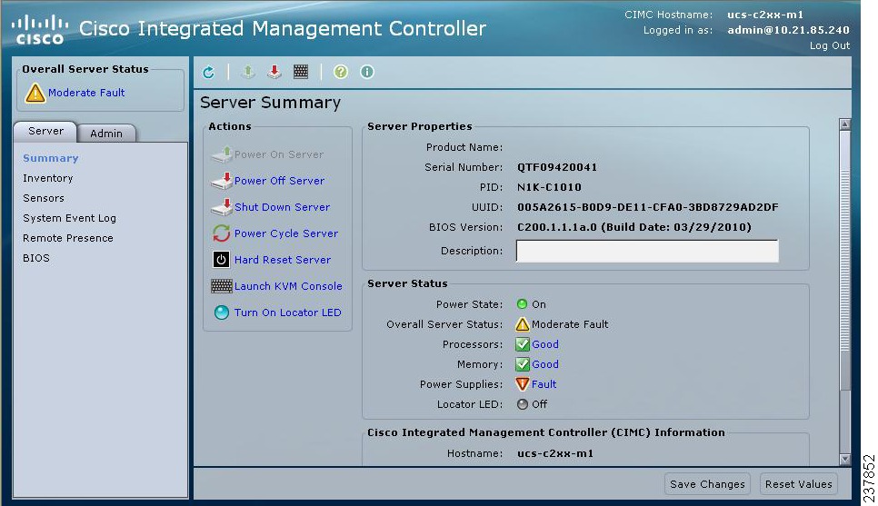
•![]() From a WEB browser, open the Server Summary window and view the server properties. See Figure 2-1 for an example.
From a WEB browser, open the Server Summary window and view the server properties. See Figure 2-1 for an example.
Example:
DOCS-CPPA# show hardware
switch# show hardware
unset
Software
loader: version unset
kickstart: version unset
system: version unset
kickstart image file is: unset
kickstart compile time: unset [unset]
system image file is: unset
system compile time: unset [unset]
Hardware
cisco unset ("unset")
unset with unset unset of memory.
Processor Board ID unset
Device name: unset
bootflash: unset kB
Disk Storage capacity for VM virtual disks: 346264 MB
Number of physical 1Gbps ethernet ports: 6
Number of CPU Cores: 12
CPU Cores details:
model name : Intel(R) Xeon(R) CPU X5650 @ 2.67GHz
model name : Intel(R) Xeon(R) CPU X5650 @ 2.67GHz
model name : Intel(R) Xeon(R) CPU X5650 @ 2.67GHz
model name : Intel(R) Xeon(R) CPU X5650 @ 2.67GHz
model name : Intel(R) Xeon(R) CPU X5650 @ 2.67GHz
model name : Intel(R) Xeon(R) CPU X5650 @ 2.67GHz
model name : Intel(R) Xeon(R) CPU X5650 @ 2.67GHz
model name : Intel(R) Xeon(R) CPU X5650 @ 2.67GHz
model name : Intel(R) Xeon(R) CPU X5650 @ 2.67GHz
model name : Intel(R) Xeon(R) CPU X5650 @ 2.67GHz
model name : Intel(R) Xeon(R) CPU X5650 @ 2.67GHz
model name : Intel(R) Xeon(R) CPU X5650 @ 2.67GHz
Kernel uptime is unset day(s), unset hour(s), unset minute(s), unset second(s)
plugin
Core Plugin, Ethernet Plugin, Virtualization Plugin
--------------------------------
Switch hardware ID information
--------------------------------
Switch is booted up
Switch type is : Nexus 1010 (Virtual Services Appliance) 2 slot Chassis
Model number is Nexus 1010
PID-VID-SN: N1K-C1010-A-1939956678133462692
--------------------------------
Chassis has 2 Module slots
--------------------------------
Module1 ok
Module type is : Nexus 1010 (Virtual Services Appliance)
0 submodules are present
Model number is Nexus 1010
H/W version is A
UUID is 03BB2905-E130-DF11-68A1-68EFBDF61D42
Manufacture date is 03/29/2010
Serial number is QCI1410A4WG
Module2 ok
Module type is : Nexus 1010 (Virtual Services Appliance)
0 submodules are present
Model number is Nexus 1010
H/W version is A
UUID is 62ED8405-7031-DF11-4DA5-68EFBDF62300
Manufacture date is 03/29/2010
Serial number is QCI1410A4LP
Figure 2-1 CIMC Window with Product ID (PID)
Step 2 ![]() Do one of the following:
Do one of the following:
•![]() If the PID displayed is N1K-C1010 on Cisco Nexus 1010 or N1K-C1010-X on Cisco Nexus 1010-X, you can proceed with the install or upgrade to Cisco Nexus 1010 Release 4.2(1)SP1(4a).
If the PID displayed is N1K-C1010 on Cisco Nexus 1010 or N1K-C1010-X on Cisco Nexus 1010-X, you can proceed with the install or upgrade to Cisco Nexus 1010 Release 4.2(1)SP1(4a).
•![]() If the PID displayed is not N1K-C1010 on Cisco Nexus 1010 or N1K-C1010-X on Cisco Nexus 1010-X, do not install or upgrade to Release 4.2(1)SP1(4a). Instead you must replace the Cisco Nexus 1010 using the RMA process.
If the PID displayed is not N1K-C1010 on Cisco Nexus 1010 or N1K-C1010-X on Cisco Nexus 1010-X, do not install or upgrade to Release 4.2(1)SP1(4a). Instead you must replace the Cisco Nexus 1010 using the RMA process.
Gathering Information About the Management Software
Before you begin the installation, you will need the following information for your Cisco Nexus 1010 or Cisco Nexus 1010-X:
Administrator Credentials
When you set up the system software, you are required to create an administrator password. Table 2-1 lists password strength guidelines:
HA Redundancy Role
The Cisco Nexus 1010 product family is provided in redundant pairs for high availability. When setting up the device, you configure a high availability role—primary or secondary. Table 2-2 describes these roles.
Note ![]() The HA standalone role is not supported for the Cisco Nexus 1010 product family. Cisco Nexus 1010 is not supported in a non HA mode.
The HA standalone role is not supported for the Cisco Nexus 1010 product family. Cisco Nexus 1010 is not supported in a non HA mode.
HA Redundancy States
Table 2-3 describes the HA redundancy states.
Domain ID
The primary and secondary Cisco Nexus 1010s use the domain ID to identify each other. The Cisco Nexus 1010s must be in the same switching domain, and share the same management IP address.
Network Uplinks
Cisco Nexus 1010 product family supports two types of network uplink configurations to connect to the network.
•![]() Flexible Network Uplink: Flexible network configuration offers complete flexibility to connect the Cisco Nexus 1010 product family to the network and allows you to achieve a maximum of six uplinks.
Flexible Network Uplink: Flexible network configuration offers complete flexibility to connect the Cisco Nexus 1010 product family to the network and allows you to achieve a maximum of six uplinks.
•![]() Static Network Uplink :In a static network configuration, the Cisco Nexus 1010 product family is connected to the network using four fixed network uplink configurations. See Network Uplink Types.
Static Network Uplink :In a static network configuration, the Cisco Nexus 1010 product family is connected to the network using four fixed network uplink configurations. See Network Uplink Types.
As a result you can connect your system to the network using one of the following five supported uplink types.
•![]() One uplink
One uplink
•![]() Two uplinks with common management and control traffic
Two uplinks with common management and control traffic
•![]() Two uplinks with common control and data traffic
Two uplinks with common control and data traffic
•![]() Three uplinks
Three uplinks
•![]() Flexible network uplink
Flexible network uplink
Note ![]() Once you configure an uplink type, the only way to modify it is to reload the software.
Once you configure an uplink type, the only way to modify it is to reload the software.
See the Cisco Nexus 1010 Software Configuration Guide, Release 4.2(1)SP1(4) for more information about network uplink types.
During the installation of Cisco Nexus 1010 product family you can setup the flexible network uplink type or the static network uplink uplink type. After you set up the uplink type, you can change the uplink type only once. See the Cisco Nexus 1010 Software Configuration Guide, Release 4.2(1)SP1(4) for information about migrating the network uplink types.
Table 2-4 Table 2-4shows the four supported network uplink types and the ports that carry each type of VLAN traffic.
VLANs
Control, and management VLANs are used by the Cisco Nexus 1010 product family for management and communication with its virtual service blades. These VLANs are added as a part of the initial setup of the management software. Control and packet VLANs are also added to each virtual service blade when it is created. The management VLAN is inherited from the Cisco Nexus 1010 product family by each virtual service blade.
If you modify a control, packet, or management VLAN on the Cisco Nexus 1010 product family , the change is effective immediately. A reload is required to effect the change of control and management VLAN on Cisco Nexus 1010. However, for service continuity, you must configure the same control and packet VLANs on the hosted VSMs. Otherwise the Cisco Nexus 1010 loses communication with its VSMs.
This section includes the following additional topics:
Management VLAN
The management VLAN is the VLAN that forwards traffic for the management port of the Cisco Nexus 1010. If your virtual service blade uses the management class of traffic, it inherits the management VLAN from the Cisco Nexus 1010.
The management VLAN is used by the outside world to reach the Cisco Nexus 1010 management 0 interface. The Cisco Nexus 1010 and its hosted Cisco Nexus 1000V VSMs share the same management VLAN. Unlike the control and packet VLANs which are set when a virtual service blade is created, the management VLAN is inherited from the Cisco Nexus 1010 by all virtual service blades it hosts.
Control VLAN
The control VLAN is a Layer 2 interface used for communication between the redundant Cisco Nexus 1010s. This interface handles low-level control packets such as heartbeats as well as any configuration data that needs to be exchanged between the Cisco Nexus 1010s.
Setting up the Primary Cisco Nexus 1010 or Cisco Nexus 1010-X
You can use this procedure to set up the management software for the following:
•![]() The primary Cisco Nexus 1010 or Cisco Nexus 1010-X in a redundant HA pair
The primary Cisco Nexus 1010 or Cisco Nexus 1010-X in a redundant HA pair
It is a recommended Cisco best practice to configure a primary Cisco Nexus 1010 or Cisco Nexus 1010-X with a secondary backup. Although you can configure a primary Cisco Nexus 1010 without a secondary backup, this configuration in a production environment is not supported.
BEFORE YOU BEGIN
•![]() You have the following information available for this Cisco Nexus 1010:
You have the following information available for this Cisco Nexus 1010:
–![]() Administrator password
Administrator password
–![]() HA role (primary or secondary)
HA role (primary or secondary)
If you do not specify an HA role, then the role is configured as primary.
–![]() Network uplink type
Network uplink type
–![]() Control VLAN ID
Control VLAN ID
–![]() Domain ID
Domain ID
–![]() Management VLAN ID
Management VLAN ID
–![]() Management 0 IP address
Management 0 IP address
This is the IP address of the management interface that appears as the mgmt0 port on the appliance.
–![]() Default gateway IP address
Default gateway IP address
–![]() SSH service key type and number of key bits
SSH service key type and number of key bits
DETAILED STEPS
Step 1 ![]() Use one of the following methods to log in to the Cisco Nexus 1010 or Cisco Nexus 1010-X CLI.
Use one of the following methods to log in to the Cisco Nexus 1010 or Cisco Nexus 1010-X CLI.
The setup wizard starts automatically.
•![]() Login from a terminal server:
Login from a terminal server:
Example:
telnet 172.25.182.99 2005
Trying 172.25.182.99...
Connected to 172.25.182.99.
Escape character is '^]'
switch#
---- System Admin Account Setup ---- Enter the password for "admin":Confirm the password for"admin":
•![]() Login from a serial over LAN connection through CIMC:
Login from a serial over LAN connection through CIMC:
Example:
ssh admin@172.25.182.230
admin@172.25.182.230's password:
switch# connect host
CISCO Serial Over LAN:
Close Network Connection to Exit
---- System Admin Account Setup ---- Enter the password for "admin":Confirm the password for"admin":
Step 2 ![]() When asked, enter and confirm the Administrator password.
When asked, enter and confirm the Administrator password.
Example:
---- System Admin Account Setup ----Confirm the password for
Enter the password for "admin": "admin":
Step 3 ![]() When asked, enter the HA role. If you do not specify a role, then primary is assigned.
When asked, enter the HA role. If you do not specify a role, then primary is assigned.
Example:
Enter HA role[primary/secondary]: primary
Note ![]() The HA standalone role is not supported for the Cisco Nexus 1010 product family. Cisco Nexus 1010 is not supported in a non HA mode
The HA standalone role is not supported for the Cisco Nexus 1010 product family. Cisco Nexus 1010 is not supported in a non HA mode
Step 4 ![]() When asked, enter the uplink type.To specify static network uplink, enter a value from 1-4. To specify flexible network uplink, enter the value 5.
When asked, enter the uplink type.To specify static network uplink, enter a value from 1-4. To specify flexible network uplink, enter the value 5.
Note ![]() Once you configure an uplink type, the only way to modify it is to reload the software.
Once you configure an uplink type, the only way to modify it is to reload the software.
Example:
Enter network-uplink type <1-5>:
1. Ports 1-2 carry all management, control and data vlans
2. Ports 1-2 management and control, ports 3-6 data
3. Ports 1-2 management, ports 3-6 control and data
4. Ports 1-2 management, ports 3-4 control, ports 5-6 data
5. Flexible
5
Step 5 ![]() When asked, enter the VLAN ID for the control VLAN.
When asked, enter the VLAN ID for the control VLAN.
Example:
Enter control vlan <1-3967, 4048-4093>: 347
Step 6 ![]() When asked, enter control uplink type.
When asked, enter control uplink type.
Example:
Enter control uplink <1-6>: 1
Step 7 ![]() When asked, enter the domain ID.
When asked, enter the domain ID.
Example:
Enter the domain id<1-4095>: 3477
Step 8 ![]() When asked, enter the VLAN ID for the management VLAN.
When asked, enter the VLAN ID for the management VLAN.
Example:
Enter management vlan<1-3967,4048-4093>: 180
Step 9 ![]() When asked, enter management uplink type.
When asked, enter management uplink type.
Example:
Enter management uplink <1-6>: 2
Step 10 ![]() When you have completed this process, the Cisco Nexus 1010 software saves the configuration and automatically reboots to configure the network uplinks.
When you have completed this process, the Cisco Nexus 1010 software saves the configuration and automatically reboots to configure the network uplinks.
The new configuration is saved into nonvolatile storage, after which the running and the startup copies of the configuration are identical.
Saving boot configuration. Please wait...
[########################################] 100%
System is going to reboot to configure network uplinks
After reboot, the default static or flexible topology will be configured. See Figure 2-2 for default flexible network uplink configuration. For more information, see the Cisco Nexus 1010 Software Configuration Guide, Release 4.2(1)SP1(4).
Figure 2-2
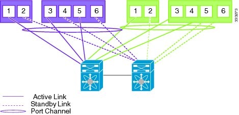
Default Flexible Network Uplink Configuration without vPC /VSS
Figure 2-3
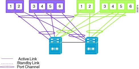
Default Flexible Network Uplink Configuration with vPC /VSS
Step 11 ![]() When asked if you want to enter the basic configuration dialog, respond yes.
When asked if you want to enter the basic configuration dialog, respond yes.
Example:
Would you like to enter the basic configuration dialog (yes/no): yes
---- Basic System Configuration Dialog ----
This setup utility will guide you through the basic configuration of
the system. Setup configures only enough connectivity for management
of the system.
*Note: setup is mainly used for configuring the system initially,
when no configuration is present. So setup always assumes system
defaults and not the current system configuration values.
Press Enter at anytime to skip a dialog. Use ctrl-c at anytime
to skip the remaining dialogs.
Step 12 ![]() When asked to create another Login account, answer no.
When asked to create another Login account, answer no.
Example:
Create another login account (yes/no) [n]: no
Step 13 ![]() When asked to configure a read-only SNMP community string, answer no.
When asked to configure a read-only SNMP community string, answer no.
Example:
Configure read-only SNMP community string (yes/no) [n]: no
Step 14 ![]() When asked to configure a read-write SNMP community string, answer no.
When asked to configure a read-write SNMP community string, answer no.
Example:
Configure read-write SNMP community string (yes/no) [n]:
Step 15 ![]() Enter a name for the appliance.
Enter a name for the appliance.
Example:
Enter the VSA name [Nexus1010]:
Step 16 ![]() When asked to configure out-of-band management, answer yes and then enter the management 0 IPv4/IPv6 address.
When asked to configure out-of-band management, answer yes and then enter the management 0 IPv4/IPv6 address.
This is the IP address of the management interface that appears as the mgmt0 port on the appliance.
Example:
Continue with Out-of-band (mgmt0) management configuration? [yes/no] [y]: yes
Mgmt0 IP address type V4/V6? (V4): V6
Mgmt0 IPv6 address: 1:a:0::2
Mgmt0 IPv6 netmask prefix (1-128): 64
Step 17 ![]() When asked to configure the default gateway, answer yes.
When asked to configure the default gateway, answer yes.
Example:
Configure the default-gateway: (yes/no) [y]: yes
IPv6 address of the default gateway: 1:a:0::1
Step 18 ![]() When asked to configure advanced IP options, answer no.
When asked to configure advanced IP options, answer no.
Example:
Configure Advanced IP options (yes/no)? [n]: no
Step 19 ![]() When asked to enable the Telnet service, answer yes.
When asked to enable the Telnet service, answer yes.
Example:
Enable the telnet service? (yes/no) [y]: yes
Step 20 ![]() When asked to enable the SSH service, answer yes and then enter the key type and number of key bits.
When asked to enable the SSH service, answer yes and then enter the key type and number of key bits.
Example:
Enable the ssh service? (yes/no) [y]: yes
Type of ssh key you would like to generate (dsa/rsa) : rsa
Number of key bits <768-2048> : 1024
Step 21 ![]() When asked to configure the NTP server, answer no.
When asked to configure the NTP server, answer no.
The configuration is summarized.
Example:
Configure NTP server? (yes/no) [n]: no
The following configuration will be applied:
Switchname n1010
interface Mgmt0
ip address 172.28.15.152 255.255.255.0
no shutdown
telnet server enable
ssh key rsa 1024 force
ssh server enable
svs-domain
control vlan 260
domain id 152
Step 22 ![]() Do one of the following:
Do one of the following:
•![]() If you do not want to edit the configuration answer no and continue with the next step.
If you do not want to edit the configuration answer no and continue with the next step.
•![]() If you want to edit the configuration, answer yes and return to Step 12 to revisit each command.
If you want to edit the configuration, answer yes and return to Step 12 to revisit each command.
Example:
Would you like to edit the configuration? (yes/no) [n]:no
Step 23 ![]() When asked to use and save this configuration, answer yes.
When asked to use and save this configuration, answer yes.

Example:
Use this configuration and save it? (yes/no) [y]: yes
[########################################] 100%
The new configuration is saved into nonvolatile storage, after which the running and the startup copies of the configuration are identical.
Note ![]() You can use the setup routine to update the configuration done in Step 12 through Step 23 at any time by entering the setup command in EXEC mode. Once setup begins, press Enter to skip a command. Use ctrl-c to skip the remaining commands.
You can use the setup routine to update the configuration done in Step 12 through Step 23 at any time by entering the setup command in EXEC mode. Once setup begins, press Enter to skip a command. Use ctrl-c to skip the remaining commands.
Step 24 ![]() You have completed this procedure. You can verify the configuration using the following command:
You have completed this procedure. You can verify the configuration using the following command:
show running configuration
!Command: show running-config
!Time: Wed Mar 7 17:10:17 2012
version 4.2(1)SP1(4)
no feature telnet
username admin password 5 $1$SeEBgc65$mXwtmD2lscaAbznFLkIRu0 role network-admin
banner motd #Nexus 1010#
ip domain-lookup
ip domain-lookup
hostname switch
snmp-server user admin network-admin auth md5 0xb64ad6879970f0e57600c443287a79f0 priv 0xb64ad6879970f0e57600c443287a79f0 localizedkey
vrf context management
vlan 1,231,423
port-channel load-balance ethernet source-mac
port-profile default max-ports 32
vdc switch id 1
limit-resource vlan minimum 16 maximum 2049
limit-resource monitor-session minimum 0 maximum 2
limit-resource vrf minimum 16 maximum 8192
limit-resource port-channel minimum 0 maximum 768
limit-resource u4route-mem minimum 32 maximum 32
limit-resource u6route-mem minimum 16 maximum 16
limit-resource m4route-mem minimum 58 maximum 58
limit-resource m6route-mem minimum 8 maximum 8
network-uplink type 1
interface GigabitEthernet1
interface GigabitEthernet2
interface GigabitEthernet3
interface GigabitEthernet4
interface GigabitEthernet5
interface GigabitEthernet6
shutdown
interface PortChannel1
virtual-service-blade vsm-1
virtual-service-blade-type name VSM-1.1
interface control vlan 423
interface packet vlan 423
ramsize 2048
disksize 3
numcpu 1
cookie 522855478
no shutdown
interface VsbEthernet1/1
interface VsbEthernet1/2
interface VsbEthernet1/3
virtual-service-blade vsm-2
virtual-service-blade-type name VSM-1.1
interface control vlan 423
interface packet vlan 423
ramsize 2048
disksize 3
numcpu 1
cookie 824895200
no shutdown
interface mgmt0
interface control0
line console
boot kickstart bootflash:/nexus-1010-kickstart-mz.4.2.1.SP1.3.41.bin
boot system bootflash:/nexus-1010-mz.4.2.1.SP1.3.41.bin
boot kickstart bootflash:/nexus-1010-kickstart-mz.4.2.1.SP1.3.41.bin
boot system bootflash:/nexus-1010-mz.4.2.1.SP1.3.41.bin
svs-domain
domain id 1900
control vlan 423
management vlan 231
svs mode L2
vnm-policy-agent
registration-ip 0.0.0.0
shared-secret **********
log-level info
Setting up the Secondary Cisco Nexus 1010 or Cisco Nexus 1010-X
You can use this procedure to set up the management software for the secondary Cisco Nexus 1010 or Cisco Nexus 1010-X in a redundant pair.
It is recommended to configure the same domain ID, uplink type, control VLAN, management VLAN, control uplink, management uplink for both primary and secondary 1010s.
DETAILED STEPS
Step 1 ![]() When asked, enter and confirm the Administrator password.
When asked, enter and confirm the Administrator password.
Example:
---- System Admin Account Setup ----Confirm the password for
Enter the password for "admin": "admin":
Step 2 ![]() When asked, enter the HA role.
When asked, enter the HA role.
Example:
Enter HA role[primary/secondary]: secondary
Step 3 ![]() When asked, enter the uplink type.
When asked, enter the uplink type.
Note ![]() Once you configure an uplink type, the only way to modify it is to reload the software.
Once you configure an uplink type, the only way to modify it is to reload the software.
Example:
Enter network-uplink type <1-5>:
1. Ports 1-2 carry all management, control and data vlans
2. Ports 1-2 management and control, ports 3-6 data
3. Ports 1-2 management, ports 3-6 control and data
4. Ports 1-2 management, ports 3-4 control, ports 5-6 data
5. Flexible
5
Step 4 ![]() When asked, enter the VLAN ID for the control VLAN.
When asked, enter the VLAN ID for the control VLAN.
Example:
Enter control vlan <1-3967, 4048-4093>: 347
Step 5 ![]() When asked, enter control uplink type.
When asked, enter control uplink type.
Example:
Enter control uplink <1-6>: 1
Step 6 ![]() When asked, enter the domain ID.
When asked, enter the domain ID.
Example:
Enter the domain id<1-4095>: 3477
Step 7 ![]() When asked, enter the VLAN ID for the management VLAN.
When asked, enter the VLAN ID for the management VLAN.
Example:
Enter management vlan<1-3967,4048-4093>: 180
Step 8 ![]() When asked, enter management uplink type.
When asked, enter management uplink type.
Example:
Enter management uplink <1-6>: 2
The following things occur on the switch:
•![]() The new configuration is saved into nonvolatile storage, after which the running and the startup copies of the configuration are identical.
The new configuration is saved into nonvolatile storage, after which the running and the startup copies of the configuration are identical.
•![]() The system reboots to configure the network uplinks.
The system reboots to configure the network uplinks.
•![]() The system restarts and synchronizes its configuration with the primary Cisco Nexus 1000V.
The system restarts and synchronizes its configuration with the primary Cisco Nexus 1000V.
Example:
Saving boot configuration. Please wait...
[########################################] 100%
System is going to reboot to configure network uplinks
HA mode set to secondary. Rebooting now...
Step 9 ![]() You have completed this procedure. You can verify the configuration using the following command:
You have completed this procedure. You can verify the configuration using the following command:
show running configuration.
Example for Network Uplink Configuration
The following example shows how to configure flexible network uplink configuration during installation:
---- System Admin Account Setup ----
Enter the password for "admin":
Confirm the password for "admin":
Enter HA role[primary/secondary]: secondary
_
Enter network-uplink type <1-5>:
1. Ports 1-2 carry all management, control and data vlans
2. Ports 1-2 management and control, ports 3-6 data
3. Ports 1-2 management, ports 3-6 control and data
4. Ports 1-2 management, ports 3-4 control, ports 5-6 data
5. Flexible
5
_
Enter control vlan <1-3967, 4048-4093>: 347
Enter control uplink <1-6>: 1
_
Enter the domain id<1-4095>: 3477
_
Enter management vlan <1-3967, 4048-4093>: 180
Enter management uplink <1-6>: 2
_
Saving boot configuration. Please wait...
[########################################] 100%
System is going to reboot to configure network uplinks
The following example shows how to configure static network uplink configuration during installation:
---- System Admin Account Setup ----
Enter the password for "admin":
Confirm the password for "admin":
Enter HA role[primary/secondary]: secondary
_
Enter network-uplink type <1-5>:
1. Ports 1-2 carry all management, control and data vlans
2. Ports 1-2 management and control, ports 3-6 data
3. Ports 1-2 management, ports 3-6 control and data
4. Ports 1-2 management, ports 3-4 control, ports 5-6 data
5. Flexible
1
_
Enter control vlan <1-3967, 4048-4093>: 300
_
Enter the domain id<1-4095>: 300
_
Enter management vlan <1-3967, 4048-4093>: 233
_
Saving boot configuration. Please wait...
[########################################] 100%
System is going to reboot to configure network uplinks
Verifying the Cisco Nexus 1010 Configuration
To verify the Cisco Nexus 1010 configuration, use the following commands:
|
|
|
|---|---|
show running-configuration |
Displays the Cisco Nexus 1010 running configuration. See Example 2-1. |
show system redundancy status |
Displays the redundancy state (active or standby) and the redundancy role (primary or secondary) for the Cisco Nexus 1010s. See Example 2-2. |
show svs domain |
Displays the domain information for the Cisco Nexus 1010: See Example 2-3. |
show network cdp neighbors |
Displays uplink connectivity for the active or standby Cisco Nexus 1010. See Example 2-4. |
Example 2-1 Setup Configuration
This example shows how to display and verify the Cisco Nexus 1010 setup configuration:
Nexus1010# show running-config
version 4.2(1)SV1(4)
username adminbackup password 5 $1$Oip/C5Ci$oOdx7oJSlBCFpNRmQK4na. role network-operato
r
username admin password 5 $1$ZMouammW$56jYJfpQuDJjDen5MABcW/ role network-admin
telnet server enable
ip domain-lookup
ip host Nexus1010 172.23.231.113
kernel core target 0.0.0.0
kernel core limit 1
system default switchport
snmp-server user admin network-admin auth md5 0xb64ad6879970f0e57600c443287a79f0 priv 0x
b64ad6879970f0e57600c443287a79f0 localizedkey
snmp-server enable traps license
vrf context management
ip route 0.0.0.0/0 172.23.231.1
switchname Nexus1010
vlan 1,231,233,280,300
vdc Nexus1010 id 1
limit-resource vlan minimum 16 maximum 513
limit-resource monitor-session minimum 0 maximum 64
limit-resource vrf minimum 16 maximum 8192
limit-resource port-channel minimum 0 maximum 256
limit-resource u4route-mem minimum 32 maximum 80
limit-resource u6route-mem minimum 16 maximum 48
network-uplink type 1
interface mgmt0
ip address 172.23.231.113/24
interface control0
boot kickstart bootflash:/nexus-1010-kickstart-mzg.4.2.1.SP1.3.bin
boot system bootflash:/nexus-1010-mzg.4.2.1.SP1.2.bin
boot kickstart bootflash:/nexus-1010-kickstart-mzg.4.2.1.SP1.3.bin
boot system bootflash:/nexus-1010-mzg.4.2.1.SP1.3.bin
svs-domain
domain id 2801
control vlan 300
management vlan 233
svs mode L2
Example 2-2 Redundancy Status
n1010# show system redundancy status
Redundancy role
---------------
administrative: primary
operational: primary
Redundancy mode
---------------
administrative: HA
operational: None
This supervisor (sup-1)
-----------------------
Redundancy state: Active
Supervisor state: Active
Internal state: Active with no standby
Other supervisor (sup-2)
------------------------
Redundancy state: Not present
---- ----
n1010#
Example 2-3 Domain
n1010# show svs domain
SVS domain config:
Domain id: 3555
Control vlan: 305
Management vlan: 233
L2/L3 Control mode: L2
L3 control interface: NA
Status: Config not pushed to VC.
n1010#
Example 2-4 CDP neighbors (standby)
switch# n1010# show network cdp neighbors
....
Device-ID Local Intrfce Hldtme Capability Platform Port ID
sfish-cat3k-K5-stack2 eth2 166 R T B S I r cisco WS-C375 GigabitEthernet1/0/23
switch#
Getting Started With Cisco Nexus 1010
After you complete the software installation, you can configure the Cisco Nexus 1010 product family. See the Cisco Nexus 1010 Software Configuration Guide, Release 4.2(1)SP1(4) for more information
The following are the basic steps in the software configuration process.
Step 1 ![]() Configuring port channels for flexible network uplink. Use this procedure to configure port channels after you set up the flexible network uplink type.
Configuring port channels for flexible network uplink. Use this procedure to configure port channels after you set up the flexible network uplink type.
Step 2 ![]() Setting up remote management. Use this procedure to set up remote management in your startup configuration for use in recovering an unreachable Cisco Nexus 1010 or Cisco Nexus 1010-X.
Setting up remote management. Use this procedure to set up remote management in your startup configuration for use in recovering an unreachable Cisco Nexus 1010 or Cisco Nexus 1010-X.
Step 3 ![]() Do one of the following to add a service blades to the new Cisco Nexus 1010 or Cisco Nexus 1010-X:
Do one of the following to add a service blades to the new Cisco Nexus 1010 or Cisco Nexus 1010-X:
•![]() Create a new virtual service blade.
Create a new virtual service blade.
•![]() Migrate an existing VSM from a VM to the Cisco Nexus 1010.
Migrate an existing VSM from a VM to the Cisco Nexus 1010.
Feature History for Software Installation
This section provides the software installation and upgrade release history.
 Feedback