Configuring IOA
In this chapter, all configuration steps relate to a reference topology shown in Figure 5-1 where SJC and RTP represent two sites connected through the WAN or MAN ISLs. In this example, sjc-sw2 and rtp-sw2 represent the core switches where IOA is deployed. sjc-sw1 and rtp-sw1 are edge switches that has the hosts or targets connected to them.
Figure 5-1 IOA CLI Reference Topology
The process of configuring IOA involves a number of configuration tasks that should be completed in order.
On each IOA switch, complete the following configurations:
On the master IOA switch, complete the following configurations:
Enabling Clustering
The first step in the process of configuring IOA is to enable clustering in all of the IOA switches.
To enable or disable the IOA cluster on sjc-sw2, perform this task:
| |
|
|
Step 1 |
sjc-sw2# conf t sjc-sw2(config)# |
Enters configuration mode. |
| Step 2 |
sjc-sw2(config)# feature cluster |
Enables clustering. |
sjc-sw2(config)# no feature cluster |
Disables clustering. |
To complete the configuration for the reference topology, enable clustering in rtp-sw2.
Enabling the IOA Service
After enabling the IOA cluster, the second step in the process of configuring IOA is to enable the IOA service on each of the IOA switches.
To enable the IOA service on sjc-sw2, perform this task:
| |
|
|
Step 1 |
sjc-sw2# config t |
Enters configuration mode. |
| Step 2 |
sjc-sw2(config)# feature ioa |
Enables IOA feature. |
sjc-sw2(config)# no feature ioa |
Disables IOA feature. |
To complete the configuration for the reference topology, enable the IOA service in rtp-sw2.
Classifying the Switch to IOA Site
Each of the IOA switches need to be classified into a site. Make sure that you classify only the IOA switches within the physical site into an IOA site.
To classify an IOA switch into the SJC site, perform this task:
| |
|
|
Step 1 |
sjc-sw2# config t sjc-sw2(config)# |
Enters configuration mode. |
Step 2 |
sjc-sw2(config)# ioa site-local SJC |
Configures the site to which the switch belongs. The maximum name length is restricted to 31 alphabetical characters.
Note This command configures the site to which the switch belongs across all the IOA clusters that the switch participates in. This command configures the site to which the switch belongs across all the IOA clusters that the switch participates in.
|
To complete the configuration for the reference topology, classify rtp-sw2 into the RTP site.
Configuring IOA Interfaces
After enabling the cluster and enabling IOA, configure the IOA interfaces on the switch.
To provision an IOA interface, perform this task:
| |
|
|
Step 1 |
sjc-sw2# config t sjc-sw2(config)# |
Enters configuration mode. |
Step 2 |
sjc-sw2(config)# interface ioa 2/1 |
Configures IOA on service engine 1 in slot 2. |
Step 3 |
sjc-sw2(config)# interface ioa 2/1 |
Configures IOA on service engine 2 in slot 2.
Note Service engines 2, 3, and 4 are available only on the SSN-16 module. The appropriate IOA license is checked out as a part of the creation of the interface.
A standard MDS notation is used to denote the IOA interfaces: ioa slot / service engine. For example, ioa2/1 refers to Slot 2, Service Engine 1. In the case of the MSM-18/4 Module and 9222i Switch, only one service engine exists and so only ioa2/1 is valid. In the case of the SSN-16 Module, four service engines exist and so ioa2/1, ioa2/2, ioa2/3, and ioa2/4 are valid interfaces. |
Step 4 |
sjc-sw2(config)# no interface ioa 2/2 |
Deletes the IOA interface.
Note Before deleting an IOA interface, you must remove the IOA interface from the cluster.
|
Step 5 |
sjc-sw2(config-if)# no shutdown |
Enables the IOA interface. |
Step 6 |
sjc-sw2(config-if)# shutdown |
Disables the IOA interface. |

Note FCIP and IOA are not supported on the same engine.
To complete the configuration for the reference topology, configure the interfaces in rtp-sw2.
Displaying IOA Interface Status
After configuring the IOA interface, use the show int command to show whether the IOA interface is down. The interface is down until the interface is added to a cluster.
sjc-sw2# show interface ioa 2/1
ioa2/1 is down (Not in any Cluster)
0 device packets in, 0 device packets out
0 device bytes in, 0 device bytes out
0 peer packets in, 0 peer packets out
0 peer bytes in, 0 peer bytes out
0 i-t create request, 0 i-t create destroy
0 i-t activate request, 0 i-t deactivate request
Possible reasons for the interface being down are as follows:
- Administratively down—The interface is shut down.
- Not in any cluster—The interface is not part of any IOA cluster.
- Port software failure—A software failure has occured causing a reset of the IOA service engine.
- No license—The interface does not have a valid IOA license. The license is either not installed or all the available licenses are in use.
Configuring an IOA Cluster
To configure a cluster, start with a switch and create a cluster and add the remaining IOA switches into the cluster. From this point on, all cluster parameters can be configured from this switch.
To create an IOA cluster, perform this task:
| |
|
|
Step 1 |
sjc-sw2# config t sjc-sw2(config)# |
Enters configuration mode. |
| Step 2 |
sjc-sw2(config)# ioa cluster tape_vault sjc-sw2(config-ioa-cl)# |
Assigns a user-specified name (tape_vault) to the IOA cluster. The maximum length of the name is 31 alphabetical characters. Enters the cluster configuration submode. The local switch is implicitly added to the cluster as part of this command. |
sjc-sw2(config)# no ioa cluster tape_vault |
Deletes the specified IOA cluster. |
Note You need to select a switch that you want to be the master switch as the seed switch when you create the IOA cluster. If you have multiple switches in a site, you may add all the switches in a site that you want to manage the cluster before adding the switches from the remote site.
This section includes the following topics:
Displaying IOA Cluster Status
The following examples display the cluster information:
Note You must configure at least one IOA interface on each site for the cluster to be online.
sjc-sw2# show ioa cluster
IOA Cluster is tape_vault
Cluster ID is 0x213a000dec3ee782
Is between sites SJC and RTP
Cluster Infra Status : Operational
Cluster is Administratively Up
Cluster Config Version : 26
SSL for ICN : Not Configured
sjc-sw2# show ioa cluster tape_vault
IOA Cluster is tape_vault
Cluster ID is 0x213a000dec3ee782
Is between sites SJC and RTP
Cluster Infra Status : Operational
Cluster is Administratively Up
Cluster Config Version : 26
SSL for ICN : Not Configured
A cluster can have the following statuses:
- Pending—An IOA interface needs to be added to the cluster.
- Online—The cluster is online. IOA services can be run on the cluster.
- Offline—The cluster is offline. Check the infrastructure status for more information.
The infrastructure status has the following values:
- Operational—The cluster infrastructure is operational on this switch. The IOA service will be able to use the cluster on this switch.
- Not Operational—The cluster infrastructure is not operational on this node. The IOA service will not run on this cluster on this switch.
The administrative status has the following values:
- Administratively Up—If the cluster is not online, check this status to make sure that the cluster is administratively up.
- Administratively Shutdown—The cluster was shut down.
Adding Nodes to an IOA Cluster
To add nodes to an IOA cluster, perform this task:
|
|
|
Step 1 |
sjc-sw2# config t sjc-sw2(config)# |
Enters configuration mode. |
Step 2 |
sjc-sw2(config)# ioa cluster tape_vault sjc-sw2(config-ioa-cl)# |
Enters the cluster configuration submode and adds the local switch where this command is executed into the IOA cluster. |
Step 3 |
sjc-sw2(config-ioa-cl)# node local |
Enters the node configuration submode for the local switch. The local keyword denotes the switch where the CLI command is executed.
Note You may also specify the node name of the local switch to enter submode. The node name could be either the IP address or the DNS name of the local switch.
|
|
sjc-sw2(config-ioa-cl)# node sjc-sw2 sjc-sw2(config-ioa-cl-node)# end |
Includes the switch as part of the cluster. Enters the node configuration submode. |
|
sjc-sw2(config-ioa-cl)# node rtp-sw2 sjc-sw2(config-ioa-cl-node)# end |
Includes the remote switch as part of the cluster. Alternatively, use an IPv4 or IPv6 address. Enters the node configuration submode. |
|
sjc-sw2(config-ioa-cl)# no node rtp-sw2 |
Removes the local or the remote node from the cluster. |
The following examples display the nodes information:
sjc-sw2# show ioa cluster summary
-------------------------------------------------------------------------------
Cluster Sites Status Master Switch
-------------------------------------------------------------------------------
tape_vault SJC, online 172.23.144.97
sjc-sw2# show ioa cluster tape_vault node summary
-------------------------------------------------------------------------------
Switch Site Status Master
-------------------------------------------------------------------------------
172.23.144.97(L) SJC online yes
172.23.144.98 RTP online no
sjc-sw2# show ioa cluster tape_vault node
Node 172.23.144.97 is local switch
Node is the master switch
Node 172.23.144.98 is remote switch
Node is not master switch
Adding Interfaces to an IOA Cluster
To add IOA interfaces to an IOA cluster, perform this task:
| |
|
|
Step 1 |
sjc-sw2# config t switch(config)# |
Enters configuration mode. |
Step 2 |
sjc-sw2(config)# ioa cluster tape_vault sjc-sw2(config-ioa-cl)# |
Enters the cluster configuration submode. |
| Step 3 |
sjc-sw2(config-ioa-cl)# node local |
Includes the local switch as part of the cluster. Enters the node configuration submode for the local switch. The local keyword denotes the switch where the CLI command is executed.
Note You may also specify the node name of the local switch to enter submode. The node name could be either the IP address or the DNS name of the local switch.
|
sjc-sw2(config-ioa-cl-node)# interface ioa 2/1 sjc-sw2(config-ioa-cl-node)# interface ioa 2/2 |
Adds the interfaces to the IOA cluster. |
sjc-sw2(config-ioa-cl-node)# no interface ioa 2/2 |
Removes the interface from the IOA cluster. |
| Step 4 |
sjc-sw2(config-ioa-cl)# node rtp-sw2 |
Includes the remote switch as part of the cluster. Alternatively, use a IPv4 or IPv6 address. Enters the node configuration submode. |
sjc-sw2(config-ioa-cl-node)# interface ioa 2/1 sjc-sw2(config-ioa-cl-node)# interface ioa 2/2 |
Adds the interfaces to the IOA cluster. |
sjc-sw2(config-ioa-cl-node)# no interface ioa 2/2 |
Removes the interface from the IOA cluster. |
The following examples display IOA interfaces information:
sjc-sw2# show interface ioa2/1
Member of cluster tape_vault
0 device packets in, 0 device packets out
0 device bytes in, 0 device bytes out
0 peer packets in, 0 peer packets out
0 peer bytes in, 0 peer bytes out
303 i-t create request, 300 i-t create destroy
300 i-t activate request, 0 i-t deactivate request
sjc-sw2# show ioa cluster tape_vault interface summary
-------------------------------------------------------------------------------
Switch Interface Status Flows
-------------------------------------------------------------------------------
172.23.144.97(L) ioa2/1 up --
172.23.144.97(L) ioa2/2 up --
172.23.144.98 ioa2/1 up --
172.23.144.98 ioa2/2 up --
sjc-sw2# show ioa cluster tape_vault interface
Interface ioa2/1 belongs to 172.23.144.97(L)(M)
Interface ioa2/2 belongs to 172.23.144.97(L)(M)
Interface ioa2/1 belongs to 172.23.144.98
Interface ioa2/2 belongs to 172.23.144.98
Note ( L) indicates the Local switch.
(M) indicates the Master switch.
Adding N Ports to an IOA Cluster
To add N ports to the IOA cluster, perform this task:
| |
|
|
Step 1 |
sjc-sw2# config t switch(config)# |
Enters configuration mode. |
Step 2 |
switch(config)# ioa cluster tape_vault |
Enters the cluster configuration submode. |
| Step 3 |
sjc-sw2(config-ioa-cl)# nport pwwn 10:0:0:0:0:0:0:1 site SJC vsan 100 sjc-sw2(config-ioa-cl)# nport pwwn 11:0:0:0:0:0:0:1 site RTP vsan 100 sjc-sw2(config-ioa-cl)# nport pwwn 10:0:0:0:0:0:0:2 site SJC vsan 100 sjc-sw2(config-ioa-cl)# nport pwwn 11:0:0:0:0:0:0:2 site RTP vsan 100 sjc-sw2(config-ioa-cl)# end |
Configures the site and VSAN ID of the N ports that will be a part of accelerated flows. |
sjc-sw2(config-ioa-cl)# no nport pwwn 10:0:0:0:0:0:0:1 |
Removes the N port from the IOA cluster. |
This example shows how to display N ports configuration:
sjc-sw2# show ioa cluster tape_vault nports
-------------------------------------------------------------------------------
-------------------------------------------------------------------------------
10:00:00:00:00:00:00:01 SJC 100
11:00:00:00:00:00:00:01 RTP 100
10:00:00:00:00:00:00:02 SJC 100
11:00:00:00:00:00:00:02 RTP 100
Configuring the IOA Flows
Before configuring the IOA flows, flow groups must be created.
To create a new IOA flow group and add flows, perform this task:
| |
|
|
Step 1 |
sjc-sw2# config t switch(config)# |
Enters configuration mode. |
Step 2 |
switch(config)# ioa cluster tape_vault |
Enters the cluster configuration submode. |
| Step 3 |
switch(config-ioa-cl)# flowgroup tsm |
Creates an IOA flow group. |
switch(config-ioa-cl)# no flowgroup tsm |
Deletes an IOA flow group. |
| Step 4 |
sjc-sw2(config-ioa-cl-flgrp)#
host 10:0:0:0:0:0:0:1 target 11:0:0:0:0:0:0:1
|
Creates a flow with write acceleration. |
|
sjc-sw2(config-ioa-cl-flgrp)#
host 10:0:0:0:0:0:0:2 target 11:0:0:0:0:0:0:2 tape
|
Creates a flow with tape acceleration. |
|
sjc-sw2(config-ioa-cl-flgrp)#
host 10:0:0:0:0:0:0:3 target 11:0:0:0:0:0:0:3 compression
|
Creates a flow with write acceleration and compression. |
|
sjc-sw2(config-ioa-cl-flgrp)# host 10:0:0:0:0:0:0:4 target 11:0:0:0:0:0:0:4 tape compression
|
Creates a flow with tape acceleration, and compression. |
|
sjc-sw2(config-ioa-cl-flgrp)#
no host 10:0:0:0:0:0:0:1 target 11:0:0:0:0:0:0:1
|
Removes the configured flow. |
Note We recommend that you suspend the traffic while enabling IOA for a given flow.
The following examples display the configured flow information without device alias:
sjc-sw2# show ioa cluster tape_vault flows
-------------------------------------------------------------------------------
Host WWN, VSAN WA TA Comp Status Switch,Interface
-------------------------------------------------------------------------------
10:00:00:00:00:00:00:01, 100 Y Y N online 172.23.144.97, ioa2/1
11:00:00:00:00:00:00:01, 100 172.23.144.98, ioa2/1
10:00:00:00:00:00:00:02, 100 Y Y Y online 172.23.144.97, ioa2/2
11:00:00:00:00:00:00:02, 100 172.23.144.98, ioa2/2
The following examples display the configured flow information with device alias:
sjc-sw2# show ioa cluster tape_vault flows
-------------------------------------------------------------------------------
Host WWN, VSAN WA TA Comp Status Switch,Interface
-------------------------------------------------------------------------------
host-1, 100 Y Y N online 172.23.144.97, ioa2/1
target-1, 100 172.23.144.98, ioa2/1
host-2, 100 Y Y Y online 172.23.144.97, ioa2/2
target-2, 100 172.23.144.98, ioa2/2
sjc-sw2# show ioa cluster tape_vault flows detail
Host 10:00:00:00:00:00:00:01, Target 11:00:00:00:00:00:00:01, VSAN 100
Switch 172.23.144.97 Interface ioa2/1 (Host Site)
Switch 172.23.144.98 Interface ioa2/1 (Target Site)
Host 10:00:00:00:00:00:00:02, Target 11:00:00:00:00:00:00:02, VSAN 100
Is enabled for WA, TA, Compression
Switch 172.23.144.97 Interface ioa2/2 (Host Site)
Switch 172.23.144.98 Interface ioa2/2 (Target Site)
IOA Flow Setup Wizard
You can use the IOA Flow Setup Wizard to simplify the provisioning of flows especially when there are many flows to provision, and when you add, remove, or replace host HBAs, tape drives or storage controllers.
This section includes the following topics:
Prerequisites for IOA Flow Setup Wizard
The following prerequisites must be met before you can invoke the IOA Flow Setup Wizard:
- All of the N ports of both initiators and targets that need to be accelerated must be online.
- The zoning configuration must already be in place to permit the flows that need to communicate with each other. If you are replacing a host HBA, you must update the zoning configuration to remove the faulty HBA and to add the new HBA before you invoke the IOA Flow Setup Wizard.
Using the IOA Flow Setup Wizard
To configure flows using the Flow Setup Wizard, follow these steps:
Step 1 Invoke the Flow Setup Wizard on a specific VSAN.
sjc-sw1# ioa flow-setup cluster tape_vault flowgroup repln-fg vsan 100
In the case of an IVR deployment, you can enter the following CLI command on an IVR border switch where IOA is deployed:
sjc-sw1# ioa ivr flow-setup cluster tape_vault flowgroup repln-fg
The wizard processes the active zone set for the VSAN and creates a set of candidate flows. When you use the ivr flow-setup command, the active IVR zone set is considered. The zone set may have local flows as well as flows that traverse across sites. The IOA Flow Setup Wizard runs through a series of steps as listed in this procedure to prune the list to capture only the flows that traverse across the sites that need to be accelerated.
Step 2 Classify the switches in the candidate switch list into appropriate sites.
This step is only for those switches where none of the hosts or targets have been configured yet for acceleration. From the flows in the active zone set, a candidate switch list is prepared based on where the hosts and targets are logged into.
The following switches need to be classified into appropriate sites
-------------------------------------------------------------------------------
Do you want to classify sjc-sw1 into site sjc or rtp [sjc]
Do you want to classify 172.23.144.96 into site sjc or rtp [sjc] rtp
The candidate flow list is now pruned to contain only the inter-site flows that need to be accelerated.
Step 3 The wizard displays all of the N ports that need to be classified into sites. Enter yes to classify the N ports into sites.
The following nport to site mapping needs to be configured
-------------------------------------------------------------------------------
N-Port PWWN: 10:00:00:00:00:00:00:00 Site: sjc
N-Port PWWN: 10:00:00:00:00:00:01:00 Site: sjc
N-Port PWWN: 10:00:00:00:00:00:02:00 Site: sjc
N-Port PWWN: 10:00:00:00:00:00:03:00 Site: sjc
N-Port PWWN: 10:00:00:00:00:00:04:00 Site: sjc
N-Port PWWN: 11:00:00:00:00:00:00:00 Site: rtp
N-Port PWWN: 11:00:00:00:00:00:01:00 Site: rtp
N-Port PWWN: 11:00:00:00:00:00:02:00 Site: rtp
N-Port PWWN: 11:00:00:00:00:00:03:00 Site: rtp
N-Port PWWN: 11:00:00:00:00:00:04:00 Site: rtp
Do you want to configure the n-port to site mappings? (yes/no) [yes] yes
Step 4 (Optional) Use this step only when some of the N ports such as those used in remote replication are represented as scsi-fcp(both) in the FCNS database. Enter the primary direction of the traffic that will be used by IOA to decide on what should be configured as host and target in IOA.
Replication traffic can flow in either direction.
Certain N-ports in this VSAN can act as both initiator and targets
Is the traffic flow primarily from sjc to rtp? (yes/no) [yes] yes
Step 5 The wizard configures the list of flows that are not already configured in IOA and attempts to delete the IOA flows that are not part of the zone set. This operation specifically handles removing HBAs or storage controllers. Enter yes to accept the flows that need to be accelerated. New flows that need to be accelerated are displayed.
The following flows will be configured
-------------------------------------------------------------------------------
Host: 10:00:00:00:00:00:00:00 VSAN: 100 Target: 11:00:00:00:00:00:00:00 VSAN:100
Host: 10:00:00:00:00:00:00:00 VSAN: 100 Target: 11:00:00:00:00:00:01:00 VSAN:100
Host: 10:00:00:00:00:00:00:00 VSAN: 100 Target: 11:00:00:00:00:00:02:00 VSAN:100
Host: 10:00:00:00:00:00:00:00 VSAN: 100 Target: 11:00:00:00:00:00:03:00 VSAN:100
Host: 10:00:00:00:00:00:01:00 VSAN: 100 Target: 11:00:00:00:00:00:00:00 VSAN:100
Host: 10:00:00:00:00:00:01:00 VSAN: 100 Target: 11:00:00:00:00:00:01:00 VSAN:100
Host: 10:00:00:00:00:00:01:00 VSAN: 100 Target: 11:00:00:00:00:00:02:00 VSAN:100
Host: 10:00:00:00:00:00:01:00 VSAN: 100 Target: 11:00:00:00:00:00:03:00 VSAN:100
Host: 10:00:00:00:00:00:02:00 VSAN: 100 Target: 11:00:00:00:00:00:00:00 VSAN:100
Host: 10:00:00:00:00:00:02:00 VSAN: 100 Target: 11:00:00:00:00:00:01:00 VSAN:100
Host: 10:00:00:00:00:00:02:00 VSAN: 100 Target: 11:00:00:00:00:00:02:00 VSAN:100
Host: 10:00:00:00:00:00:02:00 VSAN: 100 Target: 11:00:00:00:00:00:03:00 VSAN:100
Host: 10:00:00:00:00:00:03:00 VSAN: 100 Target: 11:00:00:00:00:00:00:00 VSAN:100
Host: 10:00:00:00:00:00:03:00 VSAN: 100 Target: 11:00:00:00:00:00:01:00 VSAN:100
Host: 10:00:00:00:00:00:03:00 VSAN: 100 Target: 11:00:00:00:00:00:02:00 VSAN:100
Host: 10:00:00:00:00:00:03:00 VSAN: 100 Target: 11:00:00:00:00:00:03:00 VSAN:100
Host: 10:00:00:00:00:00:04:00 VSAN: 100 Target: 11:00:00:00:00:00:04:00 VSAN:100
Do you want to configure these flows? (yes/no) [yes] yes
You can display the configured flow information by using the following commands:
sjc-sw1# show ioa cluster tape_vault nports
-------------------------------------------------------------------------------
-------------------------------------------------------------------------------
10:00:00:00:00:00:00:00 sjc 100
10:00:00:00:00:00:01:00 sjc 100
10:00:00:00:00:00:02:00 sjc 100
10:00:00:00:00:00:03:00 sjc 100
10:00:00:00:00:00:04:00 sjc 100
11:00:00:00:00:00:00:00 rtp 100
11:00:00:00:00:00:01:00 rtp 100
11:00:00:00:00:00:02:00 rtp 100
11:00:00:00:00:00:03:00 rtp 100
11:00:00:00:00:00:04:00 rtp 100
sjc-sw1# show ioa cluster tape_vault flows
-------------------------------------------------------------------------------
Host WWN, VSAN WA TA Comp Status Switch,Interface
-------------------------------------------------------------------------------
10:00:00:00:00:00:00:00, 100 Y N N offline --, --
11:00:00:00:00:00:00:00 --, --
10:00:00:00:00:00:01:00, 100 Y N N offline --, --
11:00:00:00:00:00:00:00 --, --
10:00:00:00:00:00:02:00, 100 Y N N offline --, --
11:00:00:00:00:00:00:00 --, --
10:00:00:00:00:00:03:00, 100 Y N N offline --, --
11:00:00:00:00:00:00:00 --, --
10:00:00:00:00:00:00:00, 100 Y N N offline --, --
11:00:00:00:00:00:01:00 --, --
10:00:00:00:00:00:01:00, 100 Y N N offline --, --
11:00:00:00:00:00:01:00 --, --
10:00:00:00:00:00:02:00, 100 Y N N offline --, --
11:00:00:00:00:00:01:00 --, --
10:00:00:00:00:00:03:00, 100 Y N N offline --, --
11:00:00:00:00:00:01:00 --, --
10:00:00:00:00:00:00:00, 100 Y N N offline --, --
11:00:00:00:00:00:02:00 --, --
10:00:00:00:00:00:01:00, 100 Y N N offline --, --
11:00:00:00:00:00:02:00 --, --
10:00:00:00:00:00:02:00, 100 Y N N offline --, --
11:00:00:00:00:00:02:00 --, --
10:00:00:00:00:00:03:00, 100 Y N N offline --, --
11:00:00:00:00:00:02:00 --, --
10:00:00:00:00:00:00:00, 100 Y N N offline --, --
11:00:00:00:00:00:03:00 --, --
10:00:00:00:00:00:01:00, 100 Y N N offline --, --
11:00:00:00:00:00:03:00 --, --
10:00:00:00:00:00:02:00, 100 Y N N offline --, --
11:00:00:00:00:00:03:00 --, --
10:00:00:00:00:00:03:00, 100 Y N N offline --, --
11:00:00:00:00:00:03:00 --, --
10:00:00:00:00:00:04:00, 100 Y N N offline --, --
11:00:00:00:00:00:04:00 --, --
If data is currently being transmitted through the flow, it is considered to be online and active. A throughput number in megabytes per second is shown for each flow that is online and active. Use the following commands to display all flows assigned to a single interface, or to display all flows assigned to all interfaces:
switch# show ioa online flows interface ioa2/1
-------------------------------------------------------------------------------
FLOW ID FLOW HOST FLOW TARGET VSAN e e MBps
-------------------------------------------------------------------------------
0 10:00:00:00:00:00:00:10 11:00:00:00:00:00:00:10 1 N Y 0.00
17 42:00:00:00:00:00:00:11 41:00:00:00:00:00:00:11 1 N Y 0.00
18 42:00:00:00:00:00:00:12 41:00:00:00:00:00:00:12 1 N Y 0.00
switch# show ioa online flows interface all
-------------------------------------------------------------------------------
FLOW ID FLOW HOST FLOW TARGET VSAN e e MBps
-------------------------------------------------------------------------------
0 10:00:00:00:00:00:00:10 11:00:00:00:00:00:00:10 1 N Y 0.00
17 42:00:00:00:00:00:00:11 41:00:00:00:00:00:00:11 1 N Y 0.00
18 42:00:00:00:00:00:00:12 41:00:00:00:00:00:00:12 1 N Y 0.00
19 42:00:00:00:00:00:00:13 41:00:00:00:00:00:00:13 1 N Y 0.00
20 42:00:00:00:00:00:00:14 41:00:00:00:00:00:00:14 1 N Y 0.00
21 42:00:00:00:00:00:00:15 41:00:00:00:00:00:00:15 1 N Y 0.00
22 42:00:00:00:00:00:00:16 41:00:00:00:00:00:00:16 1 N Y 0.00
23 42:00:00:00:00:00:00:17 41:00:00:00:00:00:00:17 1 N Y 0.00
24 42:00:00:00:00:00:00:18 41:00:00:00:00:00:00:18 1 N Y 0.00
25 42:00:00:00:00:00:00:19 41:00:00:00:00:00:00:19 1 N Y 0.00
26 42:00:00:00:00:00:00:1a 41:00:00:00:00:00:00:1a 1 N Y 0.00
27 42:00:00:00:00:00:00:1b 41:00:00:00:00:00:00:1b 1 N Y 0.00
28 42:00:00:00:00:00:00:1c 41:00:00:00:00:00:00:1c 1 N Y 0.00
29 42:00:00:00:00:00:00:1d 41:00:00:00:00:00:00:1d 1 N Y 0.00
30 42:00:00:00:00:00:00:1e 41:00:00:00:00:00:00:1e 1 N Y 0.00
31 42:00:00:00:00:00:00:1f 41:00:00:00:00:00:00:1f 1 N Y 0.00
32 42:00:00:00:00:00:00:20 41:00:00:00:00:00:00:20 1 N Y 0.00
33 42:00:00:00:00:00:00:21 41:00:00:00:00:00:00:21 1 N Y 0.00
34 42:00:00:00:00:00:00:22 41:00:00:00:00:00:00:22 1 N Y 0.00
35 42:00:00:00:00:00:00:23 41:00:00:00:00:00:00:23 1 N Y 0.00
36 42:00:00:00:00:00:00:24 41:00:00:00:00:00:00:24 1 N Y 0.00
37 42:00:00:00:00:00:00:25 41:00:00:00:00:00:00:25 1 N Y 0.00
38 42:00:00:00:00:00:00:26 41:00:00:00:00:00:00:26 1 N Y 0.00
39 42:00:00:00:00:00:00:27 41:00:00:00:00:00:00:27 1 N Y 0.00
40 42:00:00:00:00:00:00:28 41:00:00:00:00:00:00:28 1 N Y 0.00
41 42:00:00:00:00:00:00:29 41:00:00:00:00:00:00:29 1 N Y 0.00
42 42:00:00:00:00:00:00:2a 41:00:00:00:00:00:00:2a 1 N Y 0.00
43 42:00:00:00:00:00:00:2b 41:00:00:00:00:00:00:2b 1 N Y 0.00
44 42:00:00:00:00:00:00:2c 41:00:00:00:00:00:00:2c 1 N Y 0.00
45 42:00:00:00:00:00:00:2d 41:00:00:00:00:00:00:2d 1 N Y 0.00
46 42:00:00:00:00:00:00:2e 41:00:00:00:00:00:00:2e 1 N Y 0.00
47 42:00:00:00:00:00:00:2f 41:00:00:00:00:00:00:2f 1 N Y 0.00
48 42:00:00:00:00:00:00:30 41:00:00:00:00:00:00:30 1 N Y 0.00
49 42:00:00:00:00:00:00:31 41:00:00:00:00:00:00:31 1 N Y 0.00
Creating Multiple IOA Clusters on a Single Switch
Figure 5-2 illustrates the IOA implementation where the IOA service is extended across multiple sites. In the illustration, Site-SJC consolidates the tape backup from Site-RTP and Site-SAC. Each IOA cluster represents a site pair, which means there are two unique clusters. This topology provides segregation and scalability of the IOA service across multiple sites. In the Site-SJC, a single switch can participate in multiple IOA clusters.
Figure 5-2 Extended Across Multiple Sites
Note Before creating another cluster on sjc-sw2, create a third site SAC with the sac-sw2 switch. Clustering and IOA service must be enabled, and IOA interfaces must have been provisioned on the sac-sw2 switch.
To create another IOA cluster on sjc-sw2 with SAC, follow these steps:
| |
|
|
Step 1 |
sjc-sw2# config t |
Enters configuration mode. |
Step 2 |
sjc-sw2(config)# ioa cluster tape_vault_site2 |
Specifies the cluster name and enters IOA cluster configuration submode. A cluster name can include a maximum of 31 alphabetical characters. |
| Step 3 |
sjc-sw2(config-ioa-cl)# node local |
Adds the local switch to the cluster. Enters the node configuration mode. |
sjc-sw2(config-ioa-cl-node) # interface ioa2/3 |
Adds the IOA interface to the cluster. |
| Step 4 |
sjc-sw2(config-ioa-cl)# node sac-sw2 |
Adds the remote node to the cluster and enters the node configuration mode. |
sjc-sw2(config-ioa-cl-node) # interface ioa2/3 |
Adds the IOA interface to the cluster. |
The following example displays the multiple clusters created using the SJC site:
sjc-sw2# show ioa cluster summary
-------------------------------------------------------------------------------
Cluster Sites Status Master Switch
-------------------------------------------------------------------------------
tape_vault SJC, online 172.25.231.19
tape_vault_site2 SAC, online 172.25.231.19
Note You need to select a switch that you want to be the master switch as the seed switch when you create the IOA cluster. If you have multiple switches in a site, you add all the switches in a site that you want to manage the cluster before adding the switches from the remote site.
Note In this example, the SJC site may be a natural consolidation point for management, and you may choose a switch from this site as the preferred master switch.
Configuring IOA with NPV
You can use the Cisco MDS 9000 Family I/O Accelerator (IOA) with N port virtualization (NPV) to reduce the number of Fibre Channel domain IDs in SANs. Switches operating in NPV mode does not join a fabric or exchange traffic between NPV core switch links and end devices. You can deploy multiple edge switches without any shortage of domain IDs. NPV is not available in switch mode. To make NPV available on a switch, you must turn on NPV mode.
You can use the Cisco MDS 9000 Family I/O Accelerator (IOA) with N port ID virtualization (NPIV). NPIV efficiently utilizes the HBA ports on the blade servers in a data center and reduces the number of FCIDs assigned to the HBA ports.
The switches are not in NPV mode by default. NPV is supported in the following Cisco MDS 9000 switches:
- Cisco MDS 9124 Multilayer Fabric Switch
- Cisco MDS 9134 Fabric Switch
- Cisco Fabric Switch for HP c-Class BladeSystem
- Cisco Fabric Switch for IBM BladeCenter
Note Configuring IOA with NPV is supported in Cisco NX-OS Release 5.2(2) and later.
Guidelines for Configuring IOA with NPV
Follow these guidelines to configure IOA with NPV:
- Enable NPV on Cisco MDS 9124 switch or Cisco MDS 9134 switch.
- Enable NPIV on the NPV core switch.
Note To enable NPV on the NPV device switch, follow the guidelines specified in Cisco MDS 9000 Family NX-OS Interfaces Configuration Guide, Release 5.0(1a).
- You must make sure that the NP link is active.
- You must configure NPV traffic map, F-port PortChannel and multiple NP links.
- Enable IOA and configure IOA cluster on the NPV core switch and on another node in the SAN. The IOA node can reside on any other Cisco MDS switches in the SAN other than the NPV core switch.
- Add IOA interfaces to the cluster.
- Add remote node and interface of the remote node.
- Activate the IOA flows with WA, TA, compression as per the requirement.
- You can activate multiple IOA flows and multiple IOA clusters.
- You must enable NPIV on NPV devices if you are using VMware hosts or servers for multiple FDISC, fabric discovery configuration over the same NP link.
- You can use up to 100 hosts with IOA active flows over a single NP link.
- You can use up to 100 hosts with IOA active flows over a FPC (F-port PortChannel)
- Beginning with Cisco MDS 9000 NX-OS Release 5.2(2), features such as FPC, TFPC, and FlexAttach virtual pWWN are supported.
- You can have an IOA node on the NPV core switch and also on any other switches.
Configuring NPIV on an NPV Core Switch, NPV on an NPV Device, and Activating NP Link
The following procedures are used to enable NPV and NPIV:
- Enabling NPIV on the NPV core switch
- Enabling NPV on the NPV device
- Configuring the interfaces connected to the NPV core switch as NP ports
- Configuring the port VSAN for the NP ports
- Configuring NPV link as an F port on the NPV core switch
- Configuring the port VSAN for the F ports
- Configuring the other server and target ports on the NPV device as F ports
Configuring NPIV on the NPV Core Switch
To enable NPIV and NPV, perform this task:
| |
|
|
Step 1 |
switch# config t |
Enters configuration mode. |
Step 2 |
switch(config)# feature npiv |
Enables NPIV mode on the NPV core switch. |
Step 3 |
switch(config)# interface fc 2/1 switch(config-if)# switchport mode F switch(config-if)# no shutdown |
Configures the NPV core switch port as a F port and enables the interface. |
Step 4 |
switch(config)# vsan database switch(config-vsan-db)# vsan 500 interface fc2/1 |
Configures the port VSANs for the F port on the NPV core switch. |
Configuring NPV on the NPV Device, Bringing Up the NP Port and NP Uplink
To configure NPV on an NPV device, perform this task:
| |
|
|
Step 1 |
switch# config t |
Enters configuration mode. |
Step 2 |
switch(config)# feature npv |
Enables NPV mode on an NPV device. The switch is rebooted, and when it comes back up it is in NPV mode. Note: A write-erase is performed during the reboot. |
Step 3 |
switch(config)# interface fc 2/1 switch(config-if)# switchport mode NP switch(config-if)# no shutdown |
On the NPV device, selects the interfaces that will be connected to the aggregator switch, configures them as NP port and enables the interface. |
Step 4 |
switch(config)# exit |
Exits interface mode for the port. |
Step 5 |
switch(config)# vsan database switch(config-vsan-db)# vsan 500 interface fc 1/1 |
Configures the port VSANs for the NP port on the NPV device. |
Step 6 |
switch(config)# exit |
Exits interface mode for the port. |
Step 7 |
switch(config)# interface fc 1/2 - 6 switch(config-if)# switchport mode F switch(config-if)# no shutdown |
Selects the remaining interfaces (2 through 6) which might be connected to end device such as hosts or targets on the NPV-enabled device, configures them as F ports and enables the interface. |
Verifying the NPV Configuration
To view all the NPV devices in all the VSANs on the NPV core switch, enter the show fcns database command.
switch# show fcns database
--------------------------------------------------------------------------
FCID TYPE PWWN (VENDOR) FC4-TYPE:FEATURE
--------------------------------------------------------------------------
0x010000 N 20:01:00:0d:ec:2f:c1:40 (Cisco) npv
0x010001 N 20:02:00:0d:ec:2f:c1:40 (Cisco) npv
0x010200 N 21:00:00:e0:8b:83:01:a1 (Qlogic) scsi-fcp:init
0x010300 N 21:01:00:e0:8b:32:1a:8b (Qlogic) scsi-fcp:init
Total number of entries = 4
To display a list of the NPV devices that are logged in, along with VSANs, source information, pWWNs, and FCIDs, on the NPV device, enter the show npv flogi-table command.
switch# show npv flogi-table
--------------------------------------------------------------------------------
INTERFACE VSAN FCID PORT NAME NODE NAME INTERFACE
--------------------------------------------------------------------------------
fc1/19 1 0xee0008 10:00:00:00:c9:60:e4:9a 20:00:00:00:c9:60:e4:9a fc1/9
fc1/19 1 0xee0009 20:00:00:00:0a:00:00:01 20:00:00:00:c9:60:e4:9a fc1/1
fc1/19 1 0xee000a 20:00:00:00:0a:00:00:02 20:00:00:00:c9:60:e4:9a fc1/9
fc1/19 1 0xee000b 33:33:33:33:33:33:33:33 20:00:00:00:c9:60:e4:9a fc1/1
Total number of flogi = 4.
To display the status of the different servers and external interfaces, on the NPV device, enter the show npv status command.
Interface: fc1/1, VSAN: 2, FCID: 0x1c0000, State: Up
Interface: fc1/2, VSAN: 3, FCID: 0x040000, State: Up
Number of External Interfaces: 2
Interface: fc1/7, VSAN: 2, NPIV: No, State: Up
Interface: fc1/8, VSAN: 3, NPIV: No, State: Up
Number of Server Interfaces: 2
Creating and Activating an IOA Cluster
To configure IOA flows, follow the guidelines specified in Cisco MDS 9000 Family I/O Accelerator Configuration Guide, Release 4.2(1).
To verify the IOA configuration, follow the procedures specified in Cisco MDS 9000 Family I/O Accelerator Configuration Guide, Release 4.2(1).
Configuring NPV on IOA
This section describes the following configuration procedures used to configure NPV on IOA:
Enabling NPV
To enable NPV, perform this task:
| |
|
|
Step 1 |
switch# config t |
Enters configuration mode. |
Step 2 |
switch(config)# feature npv |
Enables NPV mode on a NPV device. The switch is rebooted, and when it comes back up, it is in NPV mode. Note: A write-erase is performed during the reboot. |
Step 3 |
switch(config)# switchname sjc-sw1 |
Configures the switch name. |
Step 4 |
sjc-sw1(config)# interface fc 2/1 sjc-sw1(config-if)# switchport mode NP sjc-sw1(config-if)# no shutdown |
On the NPV device, selects the interfaces that will be connected to the aggregator switch, configures them as NP port and enables the interface. |
Step 5 |
sjc-sw1(config)# vsan database sjc-sw1(config-vsan-db)# vsan 500 interface fc 1/6 |
Configures the port VSANs for the NP port on the NPV device. |
Step 6 |
sjc-sw1(config)# exit |
Exits VSAN database mode for the port. |
Step 7 |
sjc-sw1(config)# interface fc 1/7 - 9 sjc-sw1(config-if)# switchport mode F sjc-sw1(config-if)# no shutdown |
Configures the remaining interfaces (7 through 9) which might be connected to hosts as F ports and enables the interfaces. |
Enabling NPIV on the NPV Core Switches
To enable NPIV on the NPV core switches, perform this task:
| |
|
|
Step 1 |
switch# config t |
Enters configuration mode. |
Step 2 |
switch(config)# feature npiv |
Enables NPIV mode on a NPV core switch. |
Step 3 |
sjc-sw2(config)# vsan database sjc-sw2(config-vsan-db)# vsan 500 interface fc 1/6 |
Configures the port VSANs for the NP port on the NPV device. |
Step 4 |
sjc-sw2(config)# exit |
Exits VSAN dtabase mode for the port. |
Step 5 |
sjc-sw2(config)# interface fc 1/6 sjc-sw2(config-if)# switchport mode F sjc-sw2(config-if)# no shutdown |
Configures the interfaces as F mode and enables the interface. |
Verifying the Configured NP Uplinks
Use the following show commands to confirm the functioning of the configured NP uplinks on the NPV device sjc-sw1:
Interface: fc1/6, VSAN: 500, FCID: 0xaf0000, State: Up
Number of External Interfaces: 1
Interface: fc1/7, VSAN: 500, State: Up
Interface: fc1/8, VSAN: 500, State: Up
Number of Server Interfaces: 2
sjc-sw1# show interface fc 1/6
Hardware is Fibre Channel, SFP is short wave laser w/o OFC (SN)
Port WWN is 20:06:00:0d:ec:3d:92:00
Admin port mode is NP, trunk mode is off
snmp link state traps are enabled
Transmit B2B Credit is 16
Receive data field Size is 2112
5 minutes input rate 1956320 bits/sec, 244540 bytes/sec, 3617 frames/sec
5 minutes output rate 132841568 bits/sec, 16605196 bytes/sec, 11309 frames/sec
6219674043 frames input, 349356203708 bytes
36666335463 frames output, 64666483082476 bytes
36 input OLS, 23 LRR, 2 NOS, 0 loop inits
29 output OLS, 17 LRR, 14 NOS, 0 loop inits
0 receive B2B credit remaining
16 transmit B2B credit remaining
14 low priority transmit B2B credit remaining
Interface last changed at Mon Oct 10 10:07:54 2011
sjc-sw1# sh npv flogi-table
--------------------------------------------------------------------------------
INTERFACE VSAN FCID PORT NAME NODE NAME INTERFACE
--------------------------------------------------------------------------------
fc1/7 500 0xbe005a 10:00:02:c8:01:cc:01:21 10:00:00:00:11:86:00:00 fc1/6
fc1/8 500 0xbe0214 10:00:02:c8:01:cc:01:81 10:00:00:00:11:86:00:00 fc1/6
Total number of flogi = 1
Use the following show commands to confirm the functioning of the configured NP uplinks on the NPV device sjc-sw2:
sjc-sw2# show npiv status
Hardware is Fibre Channel, SFP is short wave laser w/o OFC (SN)
Port WWN is 20:09:00:0d:ec:3d:92:00
Admin port mode is F, trunk mode is off
snmp link state traps are enabled
Port mode is F, FCID is 0xbe0044
Transmit B2B Credit is 16
Receive data field Size is 2112
5 minutes input rate 0 bits/sec, 0 bytes/sec, 0 frames/sec
5 minutes output rate 8 bits/sec, 1 bytes/sec, 0 frames/sec
4283 frames input, 231280 bytes
4348 frames output, 2295004 bytes
1 input OLS, 1 LRR, 2 NOS, 0 loop inits
1 output OLS, 1 LRR, 1 NOS, 0 loop inits
16 receive B2B credit remaining
16 transmit B2B credit remaining
16 low priority transmit B2B credit remaining
Interface last changed at Fri Sep 30 09:24:40 2011
Enabling IOA on the IOA Nodes
To enable IOA on the first IOA node sjc-sw2 in site SJC, perform this task:
| |
|
|
Step 1 |
sjc-sw2# config t |
Enters configuration mode. |
Step 2 |
sjc-sw2(config)# feature cluster |
Enables the feature cluster on IOA node. |
Step 3 |
sjc-sw2(config)# feature ioa |
Enables the feature IOA on IOA node. |
To enable IOA on the first IOA node rtp-sw2 in Site RTP, perform this task:
| |
|
|
Step 1 |
sjc-sw2# config t |
Enters configuration mode. |
Step 2 |
sjc-sw2(config)# feature cluster |
Enables the feature cluster on IOA node. |
Step 3 |
sjc-sw2(config)# feature ioa |
Enables the feature IOA on IOA node. |
Classifying the Switches into IOA Sites
To configure the IOA site on sjc-sw2, perform this task:
| |
|
|
Step 1 |
sjc-sw2# config t |
Enters configuration mode. |
Step 2 |
sjc-sw2(config)# ioa site-local SJC |
Classifies the switches into IOA site. |
To configure the IOA site on rtp-sw2, perform this task:
| |
|
|
Step 1 |
rtp-sw2# config t |
Enters configuration mode. |
Step 2 |
rtp-sw2(config)# ioa site-local RTP |
Classifies the switches into IOA site. |
Configuring IOA Interfaces
To configure IOA interface on sjc-sw2, perform this task:
| |
|
|
Step 1 |
sjc-sw2# config t |
Enters configuration mode. |
Step 2 |
sjc-sw2(config)# interface ioa 1/1 sjc-sw2(config-if)# no shutdown |
Configures IOA on service engine 1 in slot 1 and enables the interface. |
To configure IOA interface on rtp-sw2, perform this task:
| |
|
|
Step 1 |
rtp-sw2# config t |
Enters configuration mode. |
Step 2 |
rtp-sw2(config)# interface ioa 1/1 rtp-sw2(config-if)# no shutdown |
Configures IOA on service engine 1 in slot 1 and enables the interface. |
Configuring IOA Cluster
To configure IOA cluster on sjc-sw2, perform this task:
| |
|
|
Step 1 |
sjc-sw2# config t |
Enters configuration mode. |
Step 2 |
sjc-sw2(config)# ioa cluster DC1 |
Configures IOA cluster. Cluster names are case sensitive. |
Configuring Nodes to the IOA Cluster
To add an IOA cluster on sjc-sw2, perform this task:
| |
|
|
Step 1 |
sjc-sw2# config t |
Enters configuration mode. |
Step 2 |
sjc-sw2(config)# ioa cluster DC1 |
Enters the IOA cluster sub mode |
Step 3 |
sjc-sw2(config-ioa-cl)# node local |
Adds the switch sjc-sw2 to the cluster. |
Step 4 |
sjc-sw2(config-ioa-cl-node)# exit |
Exits the IOA cluster node sub mode. |
Step 5 |
sjc-sw2(config-ioa-cl)# node rtp-sw2 |
Adds the remote IOA node into the same cluster. The remote node can be added into the cluster by using its switch name or IPv4/IPv6 management interface address. |
Verifying the IOA Cluster Configuration
Use the following show commands to confirm the functioning of the IOA cluster on sjc-sw2:
sjc-sw2# show ioa cluster
Cluster ID is 0x2003000573cbe602
Is between sites SJC and RTP
Cluster Infra Status : Operational
Cluster is Administratively Up
Cluster Config Version : 707
SSL for ICN : Not Configured
sjc-sw2# show ioa cluster DC1 summary
-------------------------------------------------------------------------------
Cluster Sites Status Master Switch
-------------------------------------------------------------------------------
DC1 SJC, online 10.65.217.48
sjc-sw2# show ioa cluster DC1 node
Node 10.65.217.48 is local switch
IP address is 10.65.217.48
Node is the master switch
Node 10.65.217.56 is remote switch
IP address is 10.65.217.56
Node is not master switch
Note You can use the same show command to verify the IOA configuration on rtp-sw2.
Configuring Interfaces in the IOA Cluster
To add IOA interfaces to the IOA cluster on the Master switch sjc-sw2, perform this task:
| |
|
|
Step 1 |
sjc-sw2# config t |
Enters configuration mode. |
Step 2 |
sjc-sw2(config)# ioa cluster DC1 |
Enters the IOA cluster submode. |
Step 3 |
sjc-sw2(config-ioa-cl)# node local |
Adds the switch sjc-sw2 to the cluster. |
Step 4 |
sjc-sw2(config-ioa-cl-node)# interface ioa 1/1 |
Adds the interface of the local IOA node into the cluster. |
Step 5 |
sjc-sw2(config-ioa-cl-node)# exit |
Exits the IOA cluster submode. |
Step 6 |
sjc-sw2(config-ioa-cl)# node rtp-sw2 |
Adds the remote IOA node into the same cluster. The remote node can be added into the cluster by using its switch name or IPv4/IPv6 management interface address. |
Step 7 |
sjc-sw2(config-ioa-cl-node)# interface ioa 1/1 |
Adds the interface of the remote IOA node into the cluster. |
Verifying the Cluster Interface Configuration
Use the following show commands to confirm the functioning configured cluster interface:
sjc-sw2# show interface ioa 1/1
21368133123 device packets in, 6851375618 device packets out
31397026863066 device bytes in, 476831158620 device bytes out
914301804 peer packets in, 8706253930 peer packets out
56107433228 peer bytes in, 17877494274392 peer bytes out
0 i-t create request, 0 i-t create destroy
0 i-t activate request, 0 i-t deactivate request
sjc-sw2# show ioa cluster DC1 interface summary
-------------------------------------------------------------------------------
Switch Interface Status Flows
-------------------------------------------------------------------------------
10.65.217.48(L) ioa1/1 up --
10.65.217.56 ioa1/1 up --
Note You can use the same show command to verify the IOA cluster and interface configuration on rtp-sw2.
Adding N Ports to the IOA cluster
To add N ports (hosts and targets) to the IOA cluster on the master switch sjc-sw2, perform this task:
| |
|
|
Step 1 |
sjc-sw2# config t |
Enters configuration mode. |
Step 2 |
sjc-sw2(config)# ioa cluster DC1 |
Enters the IOA cluster submode. |
Step 3 |
sjc-sw2(config-ioa-cl)# nport pwwn 10:00:02:c8:01:cc:01:01 site SJC vsan 500 |
Adds the N port in VSAN 500 to the cluster. |
Step 4 |
sjc-sw2(config-ioa-cl)# nport pwwn 10:00:02:c8:01:cc:02:01 site RTP vsan 500 |
Adds another N port in remote IOA site in the same VSAN to the cluster. |
Step 5 |
sjc-sw2(config-ioa-cl-node)# exit |
Exits the IOA cluster submode. |
Verifying the Configured N Ports in the IOA Cluster
Use the following show command to confirm the functioning of the configured N ports in the IOA cluster:
sjc-sw2# show ioa cluster DC1 nports
-------------------------------------------------------------------------------
-------------------------------------------------------------------------------
10:00:02:c8:01:cc:01:01 SITE sjc 500
10:00:02:c8:01:cc:02:01 SITE rtp 500
Note You can use the same command to verify the IOA cluster and interface configuration on rtp-sw2.
Configuring IOA Flows in the Cluster
To configure IOA flows in the IOA cluster on the master switch sjc-sw2, perform this task:
| |
|
|
Step 1 |
sjc-sw2# config t |
Enters configuration mode. |
Step 2 |
sjc-sw2(config)# ioa cluster DC1 |
Enters the IOA cluster submode. Cluster names are case sensitive. |
Step 3 |
sjc-sw2(config-ioa-cl)# flowgroup Dep1 |
Configures an IOA flow group. |
Step 4 |
sjc-sw2(config-ioa-cl-flgrp)# host 10:00:02:c8:01:cc:01:01 target 10:00:02:c8:01:cc:02:01 |
Creates an IOA flow with write acceleration. |
Step 5 |
sjc-sw2(config-ioa-cl-flgrp)# exit |
Exits IOA cluster flow group submode. |
Verifying the Configured IOA Flow
Use the following show commands to confirm the functioning of the IOA flow configuration and to verify status of the flow on the master switch sjc-sw2:
sjc-sw2# show ioa cluster DC1 flows flowgroup Dep1
-------------------------------------------------------------------------------
Host WWN, VSAN WA TA Comp Status Switch,Interface
-------------------------------------------------------------------------------
10:00:02:c8:01:cc:01:01, 500 Y N N online 10.65.217.48, ioa1/1
10:00:02:c8:01:cc:02:01 500 10.65.217.56, ioa1/1
sjc-sw2# show ioa cluster DC1 flows flowgroup Dep1 detail
Host 10:00:02:c8:01:cc:01:01, VSAN 500, Target 10:00:02:c8:01:cc:02:01, VSAN 500
Belongs to flowgroup Dep1
Switch 10.65.217.48 Interface ioa1/1 (Host Site)
Switch 10.65.217.56 Interface ioa1/1 (Target Site)
Displaying Interface Statistics
Use the following show commands to verify the IOA interface counters when live packets are ran over the IOA flow:
sjc-sw2# show interface ioa 1/1 counters
21523240117 device packets in, 6901040984 device packets out
31625069090806 device bytes in, 480287657508 device bytes out
920937376 peer packets in, 8769431691 peer packets out
56514685912 peer bytes in, 18007222544310 peer bytes out
1 i-t create request, 0 i-t create destroy
1 i-t activate request, 0 i-t deactivate request
The following example shows the average for 5minutes, 12 hours and 24 hours respectively:
sjc-sw2(config-if)# show interface ioa 1/1 counters brief
-------------------------------------------------------------------------------
Interface Rate Rate Rate Total
(5min) (12hr) (24hr) (MB)
-------------------------------------------------------------------------------
ioa1/1 0.00 0.00 0.00 0.02
sjc-sw2# show ioa internal interface ioa 1/1 summary
---- ----------------------- ---- ------------- ---- ---
FLOW HOST VSAN STATUS COMP ACC
---- ----------------------- ---- ------------- ---- ---
1 10:00:02:c8:01:cc:01:01 500 ACTIVE NO TA
Additional Configurations for the Features Supported by NPV on IOA
This section includes the following topics:
The following features are supported by NPV on IOA:
- NP link trunking
- F-PortChannel
- FlexAttach virtual pWWN
- NPV traffic management
Configuring an NP Uplink Port
To configure an NP link, you must bring up the TF-TNP link between an F port in the NPIV core switch and then configure a NP port in the NPV switch.
To configure an NPV core switch, perform this task:
| |
|
|
Step 1 |
sjc-sw2# config t |
Enters configuration mode. |
Step 2 |
sjc-sw2#(config)# feature fport-channel-trunk |
Enables the F port trunking and channeling protocol on the NPV core switch. |
Step 3 |
sjc-sw2#(config)# feature npiv |
Enables NPIV on the NPV core switch. |
Step 4 |
sjc-sw2#(config)# interface fc1/2 sjc-sw2#(config-if)# switchport mode F sjc-sw2#(config-if)# switchport trunk mode on |
Configures the port mode to auto, F, or Fx on the NPV core switch and enables Trunk mode on. |
Step 5 |
sjc-sw2#(config)# interface fc1/2 sjc-sw2#(config-if)# no shut |
Turns on the port administrative state on NPV core switch. |
To configure an NPV device switch, perform this task:
| |
|
|
Step 1 |
sjc-sw1# config t |
Enters configuration mode. |
Step 2 |
sjc-sw1(config)# interface fc 1/2 sjc-sw1(config)# switchport mode NP sjc-sw1(config-if)# switchport trunk mode on |
Configures the port mode to NP on the NPV switch and enabled Trunk mode on. |
Step 3 |
sjc-sw1(config)# interface fc1/2 sjc-sw1(config-if)# no shut |
Turns on the port administrative state on NPV core switch. |
Verifying the Configured Trunking NP Uplink Port on the NPV Core Switch
Use the following show command to confirm the functioning configured NPV core switch:
sjc-sw2(config-if)# show int fc 1/2
Hardware is Fibre Channel, SFP is short wave laser w/o OFC (SN)
Port WWN is 20:04:00:05:73:cb:e6:00
Admin port mode is auto, trunk mode is on
snmp link state traps are enabled
Transmit B2B Credit is 16
Receive data field Size is 2112
Belongs to port-channel 21
Trunk vsans (admin allowed and active) (9-13)
Trunk vsans (isolated) ()
Trunk vsans (initializing) (11-13)
5 minutes input rate 0 bits/sec, 0 bytes/sec, 0 frames/sec
5 minutes output rate 8 bits/sec, 1 bytes/sec, 0 frames/sec
231 frames input, 16680 bytes
248 frames output, 114660 bytes
1 input OLS, 1 LRR, 1 NOS, 0 loop inits
2 output OLS, 3 LRR, 0 NOS, 1 loop inits
16 receive B2B credit remaining
16 transmit B2B credit remaining
14 low priority transmit B2B credit remaining
Verifying the Configured Trunking NP Uplink Port on NPV Device Switch
Use the following show commands to confirm the functioning configured NPV device switch:
sjc-sw1(config-if)# show int fc 1/2
Hardware is Fibre Channel, SFP is short wave laser w/o OFC (SN)
Port WWN is 20:06:00:0d:ec:3d:92:00
Admin port mode is NP, trunk mode is on
snmp link state traps are enabled
Transmit B2B Credit is 16
Receive data field Size is 2112
Belongs to port-channel 21
Trunk vsans (admin allowed and active) (9-13)
Trunk vsans (isolated) ()
Trunk vsans (initializing) (11-13)
5 minutes input rate 0 bits/sec, 0 bytes/sec, 0 frames/sec
5 minutes output rate 0 bits/sec, 0 bytes/sec, 0 frames/sec
2837806124 frames input, 147817029296 bytes
26077437111 frames output, 49186719497132 bytes
36 input OLS, 23 LRR, 2 NOS, 0 loop inits
29 output OLS, 17 LRR, 14 NOS, 0 loop inits
16 receive B2B credit remaining
16 transmit B2B credit remaining
14 low priority transmit B2B credit remaining
Interface last changed at Mon Oct 10 10:07:54 2011
Note In the case of ports, after the handshake, one of the allowed VSANs is moved to Up state. All other VSANs will be in initial state even though the handshake with the peer is completed successfuly. Each VSAN is moved from initial state to Up state when a server or target logs in through the trunked F or NP ports in the corresponding VSAN. For more information about configuring ports and TF-TNP ports, refer to the Cisco MDS 9000 Family NX-OS Interfaces Configuration Guide, Release 5.0(1a).
Configuring F-PortChannel
To configure F-PortChannel (FPC) in shared mode and bring up the link between F ports on the NPIV core switches and NP ports on the NPV use the procedure in this section.
Note Configuring FPC is not supported on the MDS 91x4 switches.
Configuring F-PortChannel on the NPV Core Switch
To configure the F-PortChannel on an NPV core switch, perform this task:
| |
|
|
Step 1 |
sjc-sw2# config t |
Enters configuration mode. |
Step 2 |
sjc-sw2(config)# feature fport-channel-trunk |
Enables the F port trunking and channeling protocol on the NPV core switch. |
Step 3 |
sjc-sw2(config)# feature npiv |
Enables NPIV on the NPV core switch. |
Step 4 |
sjc-sw2(config)# interface port-channel 1 sjc-sw2(config-if)# switchport mode F sjc-sw2(config-if)# channel mode active sjc-sw2(config-if)# switchport trunk mode off sjc-sw2(config-if)# switchport rate-mode shared sjc-sw2(config-if)# exit |
Creates the PortChannel on the NPV core switch. |
Step 5 |
sjc-sw2(config)# interface fc2/1-3 sjc-sw2(config-if)# shut sjc-sw2(config-if)# switchport mode F sjc-sw2(config-if)# switchport trunk mode off sjc-sw2(config-if)# switchport speed 4000 sjc-sw2(config-if)# switchport rate-mode shared sjc-sw2(config-if)# channel-group 1 sjc-sw2(config-if)# exit |
Creates the PortChannel member interfaces on the NPV core switch. |
To configure NP-PortChannel on an NPV device switch, perform this task:
| |
|
|
Step 1 |
sjc-sw2# config t |
Enters configuration mode. |
Step 2 |
switch(config)# interface port-channel 1 switch(config-if)# switchport mode NP switch(config-if)# switchport rate-mode shared switch(config-if)# exit |
Creates the PortChannel on the NPV switch. |
Step 3 |
switch(config)# interface fc1/1-3 switch(config-if)# shut switch(config-if)# switchport mode NP switch(config-if)# switchport speed 4000 switch(config-if)# switchport rate-mode shared switch(config-if)# switchport trunk mode off switch(config-if)# channel-group 1 switch(config-if)# no shut switch(config-if)# exit |
Creates the PortChannel member interfaces on the NPV switch. |
To turn on the administrative state of all the PortChannel member interfaces in the NPV core switch, perform this task:
| |
|
|
Step 1 |
sjc-sw2# config t |
Enters configuration mode. |
Step 2 |
switch(config)# interface fc1/1-3 switch(config-if)# shut switch(config-if)# no shut switch(config-if)# exit |
Turns on the administrative state of the PortChannel members. |
To turn on the administrative state of all the PortChannel member interfaces in NPV device switch, perform this task:
| |
|
|
Step 1 |
sjc-sw2# config t |
Enters configuration mode. |
Step 2 |
switch(config)# interface fc2/1-3 switch(config-if)# shut switch(config-if)# no shut switch(config-if)# exit |
Turns on the administrative state of the PortChannel members. |
Verifying the Configured PortChannel of NP Links
Use the following show command to verify the configured PortChannel on the NPV core switch side:
sjc-sw2(config-if)# show interface port-channel 1
Hardware is Fibre Channel
Port WWN is 24:15:00:05:73:cb:e6:00
Admin port mode is NP, trunk mode is off
snmp link state traps are enabled
Trunk vsans (admin allowed and active) (500-512)
Trunk vsans (up) (500,512)
Trunk vsans (isolated) ()
Trunk vsans (initializing) (501-511)
5 minutes input rate 0 bits/sec, 0 bytes/sec, 0 frames/sec
5 minutes output rate 0 bits/sec, 0 bytes/sec, 0 frames/sec
792 frames input, 51848 bytes
811 frames output, 417880 bytes
2 input OLS, 2 LRR, 1 NOS, 0 loop inits
3 output OLS, 4 LRR, 0 NOS, 2 loop inits
Interface last changed at Wed Oct 12 08:12:36 2011
Use the following show commands to verify that the configured PortChannel on the NPV device switch side:
switch# show interface port-channel 1
port-channel 1 is trunking
Hardware is Fibre Channel
Port WWN is 24:15:00:05:73:cb:e6:00
Admin port mode is auto, trunk mode is off
snmp link state traps are enabled
Trunk vsans (admin allowed and active) (500-512)
Trunk vsans (up) (500,512)
Trunk vsans (isolated) ()
Trunk vsans (initializing) (501-511)
5 minutes input rate 0 bits/sec, 0 bytes/sec, 0 frames/sec
5 minutes output rate 0 bits/sec, 0 bytes/sec, 0 frames/sec
792 frames input, 51848 bytes
811 frames output, 417880 bytes
2 input OLS, 2 LRR, 1 NOS, 0 loop inits
3 output OLS, 4 LRR, 0 NOS, 2 loop inits
Interface last changed at Wed Oct 12 08:12:36 2011
Example for Configuring TF-TNP PortChannel Links
This example shows the following configuration procedures used to change the PortChannels in dedicated mode to bring up the TF-TNP PortChannel link between TF ports in the NPIV core switch, and TNP ports in the NPV switch.
Configuring the PortChannel on the NPV Core Switch
To configure the PortChannel on an NPV core switch, perform this task:
| |
|
|
Step 1 |
sjc-sw2# config t |
Enters configuration mode. |
Step 2 |
switch(config)# feature fport-channel-trunk |
Enables the F port trunking and channeling protocol on the NPV core switch. |
Step 3 |
switch(config)# feature npiv |
Enables NPIV on the NPV core switch. |
Step 4 |
switch(config)# interface port-channel 1 switch(config-if)# switchport mode F switch(config-if)# switchport rate-mode dedicated switch(config-if)# channel mode active switch(config-if)# exit |
Creates the PortChannel on the NPV switch. |
Step 5 |
switch(config)# interface fc2/1-3 switch(config-if)# shut switch(config-if)# switchport mode F switch(config-if)# switchport speed 4000 switch(config-if)# switchport rate-mode dedicated switch(config-if)# switchport trunk mode on switch(config-if)# channel-group 1 switch(config-if)# exit |
Creates the PortChannel member interfaces on the NPV core switch. |
Configuring PortChannel on the NPV Device Switch
To configure the PortChannel on an NPV device switch, perform this task:
| |
|
|
Step 1 |
sjc-sw1# config t |
Enters configuration mode. |
Step 2 |
switch(config)# interface port-channel 1 switch(config-if)# switchport rate-mode dedicated switch(config-if)# switchport mode NP switch(config-if)# no shutdown switch(config-if)# exit |
Creates the PortChannel on the NPV device switch. |
Step 3 |
switch(config)# interface fc2/1-3 switch(config-if)# shut switch(config-if)# switchport mode NP switch(config-if)# switchport speed 4000 switch(config-if)# switchport rate-mode dedicated switch(config-if)# switchport trunk mode on switch(config-if)# channel-group 1 switch(config-if)# exit |
Creates the PortChannel member interfaces on the NPV device switch. |
To turn on the administrative state of all the PortChannel member interfaces in NPV core switch, perform this task:
| |
|
|
Step 1 |
sjc-sw2# config t |
Enters configuration mode. |
Step 2 |
switch(config)# interface fc2/1-3 switch(config-if)# shut switch(config-if)# no shut switch(config-if)# exit |
Turn on the administrative state of the PortChannel members. |
To turn on the administrative state of all the PortChannel member interfaces in NPV device switch, perform this task:
| |
|
|
Step 1 |
sjc-sw2# config t |
Enters configuration mode. |
Step 2 |
switch(config)# interface fc1/1-3 switch(config-if)# shut switch(config-if)# no shut switch(config-if)# exit |
Turn on the administrative state of the PortChannel members. |
Note The speed configuration must be the same for all member interfaces in a PortChannel. You must ensure that the required bandwidth is available to all the ports while configuring the channel in dedicated mode.
Verifying the Configured PortChannel of TF-TNP Links
Use the following show commands to verify the configured PortChannel on the NPV core switch side:
sjc-sw2# show interface port-channel 1
port-channel 1 is trunking
Hardware is Fibre Channel
Port WWN is 24:15:00:05:73:cb:e6:00
Admin port mode is auto, trunk mode is on
snmp link state traps are enabled
Trunk vsans (admin allowed and active) (500-512)
Trunk vsans (up) (500,512)
Trunk vsans (isolated) ()
Trunk vsans (initializing) (501-511)
5 minutes input rate 0 bits/sec, 0 bytes/sec, 0 frames/sec
5 minutes output rate 0 bits/sec, 0 bytes/sec, 0 frames/sec
792 frames input, 51848 bytes
811 frames output, 417880 bytes
2 input OLS, 2 LRR, 1 NOS, 0 loop inits
3 output OLS, 4 LRR, 0 NOS, 2 loop inits
Interface last changed at Wed Oct 12 08:22:36 2011
Use the following show commands to verify the configured PortChannel on the NPV device switch side:
sjc-sw2# show interface port-channel 1
port-channel 1 is trunking
Hardware is Fibre Channel
Port WWN is 24:15:00:05:73:cb:e6:00
Admin port mode is auto, trunk mode is on
snmp link state traps are enabled
Trunk vsans (admin allowed and active) (500-512)
Trunk vsans (up) (500,512)
Trunk vsans (isolated) ()
Trunk vsans (initializing) (501-511)
5 minutes input rate 0 bits/sec, 0 bytes/sec, 0 frames/sec
5 minutes output rate 0 bits/sec, 0 bytes/sec, 0 frames/sec
792 frames input, 51848 bytes
811 frames output, 417880 bytes
2 input OLS, 2 LRR, 1 NOS, 0 loop inits
3 output OLS, 4 LRR, 0 NOS, 2 loop inits
Interface last changed at Wed Oct 12 08:22:36 2011
Configuring FlexAttach Virtual pWWN on an NPV Switch
The FlexAttach virtual pWWN feature facilitates server and configuration management. In a SAN environment, the server installation or replacement requires interaction and coordination among the SAN and server administrators. It is important that the SAN configuration does not change when a new server is installed, or when an existing server is replaced.
FlexAttach virtual pWWN minimizes the interaction between the server administrator and the SAN administrator by abstracting the real pWWN using virtual pWWNs. When FlexAttach virtual pWWN is enabled on an interface, a virtual pWWN is assigned to the server interface. The real pWWN is replaced by a virtual pWWN, which is used for a SAN configuration such as zoning.
With pWWNs configured on NPV switch in various forms as described in the next section, IOA works seamlessly with pWWNs. The pWWNs feature is enabled automatically, manually, or by mapping pWWN to virtual pWWN.
Automatically Enabling FlexAttach Virtual pWWN
The virtual pWWN is enabled automatically on all of the NPV switches or per port on the NPV device. When enabled automatically, a virtual WWN is generated from the device switch WWN. This WWN is used as the virtual pWWN. Virtual pWWNs are generated using the local switch WWNs.
Note The port must be in a shut state when the virtual pWWN is enabled.
To enable virtual pWWN automatically, perform this task:
| |
|
|
Step 1 |
sjc-sw2# config t |
Enters configuration mode. |
Step 2 |
swtich(config)# flex-attach virtual-pwwn auto [interface interface-list] |
Enables FlexAttach virtual pWWN automatically for the interfaces. |
Step 3 |
switch(config)# flex-attach commit |
Commits the configuration. |
Manually Enabling FlexAttach Virtual pWWN
You can manually assign a WWN to the interface, without generating it through the switch. Several checks are done by the NPV core to ensure the uniqueness of virtual pWWNs in the switch. When duplicate virtual pWWNs are configured, the subsequent logins are rejected by the NPV core switch.
Note ● Some ports may be in automode, some in manual mode, and the virtual pWWNs need not be assigned.
- The port must be in a shut state when a virtual pWWN is enabled.
- The interface mentioned in the interface value must be in a shut state.
To enable virtual pWWN manually, perform this task:
| |
|
|
Step 1 |
switch# config t |
Enters configuration mode. |
Step 2 |
swtich(config)# flex-attach virtual-pwwn vpwwn interface interface |
Enables FlexAttach virtual pWWN manually for the interfaces. |
Step 3 |
switch(config)# flex-attach commit |
Commits the configuration. |
Verifying the Configured FlexAttach Virtual pWWN
Use the following show command to verify the type and value of virtual pWWNs are correct:
sjc-sw1# show flex-attach virtual-wwn
VIRTUAL PORT WWNS ASSIGNED TO INTERFACES
----------------------------------------------------------------------
VSAN INTERFACE VIRTUAL-PWWN AUTO LAST-CHANGE
----------------------------------------------------------------------
1 fc1/1 00:00:00:00:00:00:00:00
1 fc1/2 22:73:00:05:30:01:6e:1e TRUE Thu Jan 31 01:58:52 2008
1 fc1/3 22:5e:00:05:30:01:6e:1e TRUE Thu Jan 31 01:58:52 2008
1 fc1/4 22:5f:00:05:30:01:6e:1e TRUE Thu Jan 31 01:58:52 2008
1 fc1/5 22:74:00:05:30:01:6e:1e TRUE Thu Jan 31 01:26:24 2008
1 fc1/6 22:60:00:05:30:01:6e:1e TRUE Thu Jan 31 01:58:52 2008
1 fc1/7 22:61:00:05:30:01:6e:1e TRUE Thu Jan 31 01:58:52 2008
1 fc1/8 22:62:00:05:30:01:6e:1e TRUE Thu Jan 31 01:58:52 2008
1 fc1/9 22:63:00:05:30:01:6e:1e TRUE Thu Jan 31 01:58:52 2008
1 fc1/10 22:64:00:05:30:01:6e:1e TRUE Thu Jan 31 01:58:52 2008
1 fc1/11 22:65:00:05:30:01:6e:1e TRUE Thu Jan 31 01:58:52 2008
1 fc1/12 22:66:00:05:30:01:6e:1e TRUE Thu Jan 31 01:58:52 2008
Verifying the Configured FlexAttach Virtual pWWN
Use the following show commands to verify that the end device is logged with the correct virtual WWNs:
switch# show fcns database
--------------------------------------------------------------------------
FCID TYPE PWWN (VENDOR) FC4-TYPE:FEATURE
--------------------------------------------------------------------------
0x010000 N 20:01:00:0d:ec:2f:c1:40 (Cisco) npv
0x010001 N 20:02:00:0d:ec:2f:c1:40 (Cisco) npv
0x010200 N 21:00:00:e0:8b:83:01:a1 (Qlogic) scsi-fcp:init
0x010300 N 21:01:00:e0:8b:32:1a:8b (Qlogic) scsi-fcp:init
Total number of entries = 4
Configuring NPV Traffic Management on NPV Switches with IOA
Configuring NPV traffic management involves configuring a list of external interfaces to the servers, and enabling or disabling disruptive load balancing. The NPV traffic management feature is enabled after configuring NPV.
Configuring a List of External Interfaces per Server Interface
A list of external interfaces is linked to the server interfaces when the server interface is down, or if the specified external interface list includes the external interface already in use.
To configure the list of external interfaces per server interface, perform this task:
| |
|
|
Step 1 |
sjc-sw2# config t |
Enters configuration mode. |
Step 2 |
switch(config)# npv traffic-map server-interface fc 1/1-3 external-interface fc 1/8-10 |
Allows you to configure a list of external FC interfaces to a range of server interface. |
Step 3 |
switch(config)# npv traffic-map server-interface fc1/1-3 external-interface port-channel 10-12 |
Allows you to configure a list of external PortChannel interfaces per server interface. |
Step 4 |
switch(config)# no npv traffic-map server-interface fc 1/1-3 external-interface fc 1/8-10 |
Disables the NPV traffic management feature on the NPV device switch. |
Note You must map the non-PortChannel interfaces and PortChannel interfaces to the server interfaces, in two steps.
Enabling or Disabling the Global Policy for Disruptive Load Balancing
Disruptive load balancing allows you to review the load on all the external interfaces and balance the load disruptively. Disruptive load balancing is done by moving the servers using heavily loaded external interfaces, to the external interfaces running with fewer loads.
To enable or disable the global policy for disruptive load balancing, perform this task:
| |
|
|
Step 1 |
sjc-sw2# config t |
Enters configuration mode. |
Step 2 |
switch(config)# npv auto-load-balance disruptive |
Enables disruptive load balancing on the NPV device. |
Step 3 |
switch(config)# no npv auto-load-balance disruptive |
Disables disruptive load balancing on the NPV device. |
Verifying the NPV Traffic Management on an NPV Switch
Use the following show command to display the NPV traffic map on an NPV switch:
switch# show npv traffic-map
NPV Traffic Map Information:
----------------------------------------
----------------------------------------
----------------------------------------
Use the following show command to display the NPV internal traffic details on an NPV switch:
switch# show npv internal info traffic-map
NPV Traffic Map Information:
----------------------------------------
----------------------------------------
----------------------------------------
Example for Implementing IOA with NPV
In this implementation example, an NPIV-capable server is the host directly connected to the NPV core (NPIV-enabled) switch which also acts as an IOA node. The host sends data to the target over IOA flows.
To enable NPIV on NPV core switch, perform this task:
| |
|
|
Step 1 |
sjc-sw2# config t |
Enters configuration mode. |
Step 2 |
sjc-sw1(config)# feature npiv |
Enables NPIV mode on a NPV core switch. |
To enable IOA on all the IOA nodes and to bring up the IOA flows, perform this task:
| |
|
|
Step 1 |
sjc-sw2# config t |
Enters configuration mode. |
Step 2 |
sjc-sw1(config)# feature npiv |
Enables NPIV mode on a NPV nodes switches. |
Verifying the IOA Configuration
Use the following show command to verify the IOA configuration:
sjc-sw1# show npiv status
Applying ASCII Configuration back to IOA Switches
To write erase, reload and then restore two switches that have an ioa cluster configured, perform this task:
| |
|
|
Step 1 |
switch# config t |
Enters configuration mode. |
Step 2 |
switch(config)# copy running-config bootflash: ioa_master |
Saves the running-config locally on the switch. |
Step 3 |
Switch(config)# boot system bootflash: m9250-s5ek9-mz.6.2.5b2.bin |
Sets the boot variable to a different kickstart image. |
Step 4 |
Switch(config)# boot system bootflash: m9250-s5ek9-mz.6.2.5b2.bin |
Sets the boot variable to a different system image. |
Step 5 |
Switch(config)# copy running-config startup-config |
Saves the boot variables that were configured in step 3 and step 4 to the startup configuration. |
Step 6 |
Switch(config)# write erase |
Will erase the startup configuration, but the boot variables and management IP address will not be erased. |
Step 7 |
Switch(config)# reload (Do steps 1-7 on slave IOA switches as well) |
Reload the switches with the new kickstart and system image.
Warning Once the switch has come up, you will need to configure the admin account password. Once you have done that, you will be asked if you would like to enter the basic configuration dialog. You can choose no and log onto the switch with the admin account password that you just configured. This must be done from the console port.
|
Step 8 |
a) conf t b) feature cluster c) feature ioa d) ioa site-local site name e) interface ioa x/y f) no shut |
Enables the cluster and ioa features on the switch. Configure the ioa site name and provision an ioa interface. Perform these commands on both master and slave switches. |
Step 9 |
a) conf t b) ioa cluster name c) node local d) interface ioa x/y e) node remote IP f) interface ioa x/y |
Create a cluster and add the local and remote node to the cluster by executing the following commands on the master swich.
Note These commands only need to be executed on the master switch. Do not run these commands on the slave switch. The interface specified in step d must exist on the master and the interface specified in step f must exist on the slave.
|
Step 10 |
Switch# Copy bootflash: ioa_master running-config [echo-commands] |
Copy the ASCII configuration to the running configuration on the master switch. echo-commands will echo the command before applying the config. |
Step 11 |
Switch# copy bootflash: ioa_slave running-config [echo-commands] |
Copy the ASCII configuration to the running configuration on the slave switch. echo-commands will echo the command before applying the config.
Note After copying the ASCII config, the boot variables will not be pointing to the images that were specified in steps 3 and 4. The boot variables will be pointing to whatever the saved boot variables are in the saved startup-config file. User should repeat steps 3 and 4 and do a "copy running-config startup-config.
|
Applying the ascii configuration back to the switches will result in some errors on the master and slave switch but they can be ignored since the IOA cluster has already been set up on both switches.
Additional Configurations
This section includes the following topics:
Shutting Down a Cluster
To shut down a cluster, perform this task:
| |
|
|
Step 1 |
sjc-sw2# config t |
Enters configuration mode. |
Step 2 |
sjc-sw2(config)# ioa cluster tape_vault |
Specifies the cluster name and enters IOA cluster configuration submode. A cluster name can include a maximum of 31 alphabetical characters. |
Step 3 |
sjc-sw2(config-ioa-cl)# shut |
Shuts down the cluster. This command must be used to recover a cluster when it is partitioned. The change can be disruptive. For more information, see “Cluster Recovery Scenarios. |
Load Balancing the Flows
To load balance the flows, perform this task:
| |
|
|
Step 1 |
sjc-sw2# config t |
Enters configuration mode. |
Step 2 |
sjc-sw2(config)# ioa cluster tape_vault |
Enters the cluster configuration mode. |
| Step 3 |
sjc-sw2(config-ioa-cl)# load-balancing |
Load balances all the IOA flows. This process is disruptive and causes the hosts to relogin to targets. This command will take some time to execute depending on the number of flows. You should not abort the command in the middle of its execution. |
sjc-sw2(config-ioa-cl)# load-balancing enable |
This command turns on the load-balancing attribute for the new flows. You may enter t his command only when you abort the load-balancing command process. |
sjc-sw2(config-ioa-cl)# load-balancing 11:22:33:44:55:66:77:88 |
Load balances specified targets in the IOA flows. This process is disruptive and causes the hosts to relogin to targets. The load-balancing command will take some time to execute depending on the number of flows. You should not abort the command in the middle of its execution. |
Setting the Tunable Parameters
To set the following tunable parameters based on your deployment requirements, perform this task:
|
|
|
sjc-sw2(config-ioa-cl)# tune round-trip-time ms |
Specifies the round-trip time in milliseconds. It is the time taken by the IOA data packet to traverse between two sites. The value can vary from 1 to 100 ms. 15 ms is the default. |
sjc-sw2(config-ioa-cl)# tune lrtp-retx-timeout msec |
Specifies the LRTP retransmit timeout in milliseconds. It is the time to wait before LRTP starts retransmitting packets. The value can vary from 500 to 5000 msec. 2500 msec is the default. |
Caution
The following are advanced tunable parameters, and you must consult the Cisco Services and Support team before tuning these parameters.
To set the the following advanced tunable parameters based on your deployment requirements, perform this task:
| |
|
|
Step 1 |
sjc-sw2# config t |
Enters configuration mode. |
Step 2 |
sjc-sw2(config)# ioa cluster tape_vault |
Enters the cluster configuration mode. |
Step 3 |
sjc-sw2(config-ioa-cl)# tune timer rscn-suppression seconds |
Specifies the IOA RSCN suppression timer value. It is the amount of time the IOA process waits before it queries FCNS (name server) after learning about changes in the network. This helps to alleviate the number of duplicate or repeating queries in case of rapid network changes. The value can vary from 1 to 10 seconds. 5 seconds is the default. |
Step 4 |
sjc-sw2(config-ioa-cl)# tune timer load-balance target seconds |
Specifies a IOA target load-balance timer value. It is the amount of time the IOA process waits before it attempts to load balance all IT Nexuses of a certain target port after a change in connectivity has been detected. The value can vary from 2 to 30 seconds. 2 seconds is the default. |
Step 5 |
sjc-sw2(config-ioa-cl)# tune timer load-balance global seconds |
Specifies a global IOA load-balance timer value. It is the amount of time the IOA process waits before it attempts to load balance all IT Nexuses configured in a cluster after a change in connectivity has been detected. The value can vary from 5 to 30 seconds. 5 seconds is the default. |
Step 6 |
sjc-sw2(config-ioa-cl)# tune ta-buffer-size KB |
Specifies the tape acceleration buffer size in KB. It is the amount of buffering allowed for flow control during tape acceleration. The value can vary from 64 to 12288 KB or Auto. Auto is the default. Auto option takes WAN latencies and speed of the tape device into account to provide optimum performance. |
Step 7 |
sjc-sw2(config-ioa-cl)# tune wa-buffer-size MB |
Specifies the write acceleration buffer size in MB. It is the amount of buffering allowed for flow control during write acceleration. The value can vary from 50 to 100 MB. 70 MB is the default. |
Step 8 |
sjc-sw2(config-ioa-cl)# tune wa-max-table-size KB |
Specifies the Write Max Table size in KB. It is the maximum number of active exchanges supported on an IOA flow. The value can vary from 4 to 64 KB. 4 KB is the default. |
Changing the Node Description and IP Address of an IOA Cluster
To perform any of the following tasks, follow the steps defined in the Changing the Node Description and IP Address of an IOA Cluster:
- Change the node-description (IP address) and node IP-address of a cluster.
- Change node-description(DNS name) of a cluster.
- Change the node-description from IP address to DNS name and vice versa.
Changing the Node Description and IP Address of an IOA Cluster
To change the node description and IP address of an IOA node in the existing IOA cluster:
Step 1 Shut down the IOA cluster on the switch1.
Step 2 Shut down the IOA cluster on the switch2.
Step 3 Remove the IOA cluster on the switch2.
Step 4 Remove the node of switch2 in the switch1.
Step 5 Do one of the following tasks based on what you want to perfom on the switch:
- Change the management interface IP address.
- Change the IP address and the switch name.
- Enable or disable the DNS configuration.
Step 6 Change the node description using the node id id node-description ip-address ip address command on switch1.
This step may vary depending on when the node description (DNS name) needs to be changed or node description and node IP address to be changed.
Step 7 Shut down the IOA cluster on the switch1.
Step 8 Add switch2 node with new description and the IP address.
Step 9 Add IOA interfaces on switch2.
Configuration Example for Changing the Node Description and Node IP Address of an IOA Cluster
This example shows the following configuration procedures used to change the description and IP address:
Shut Down the IOA Cluster on switch1
To shut down the IOA cluster on switch1 enter this command:
sw-231-19(config)# show ioa cluster c1 node summary
-------------------------------------------------------------------------------
Switch Site Status Master Node ID
-------------------------------------------------------------------------------
172.25.231.14 site3 online no 2
172.25.231.19(L) site2 online yes 1
sw-231-19(config)# ioa cluster c1
sw-231-19(config-ioa-cl)# sh
This change can be disruptive. Please ensure you have read the "IOA Cluster Recovery Procedure" in the configuration guide. -- Are you sure you want to continue? (y/n) [n] y
2011 Apr 12 07:02:21 sw-231-19 %CLUSTER-2-CLUSTER_LOCAL_NODE_EXIT: Local Node 0x1 has left the Cluster 0x5000530019f08076
Shut Down the IOA Cluster on switch2
To shut down the IOA cluster on switch2 enter this command:
sw-231-14(config)# ioa cluster c1
sw-231-14(config-ioa-cl)# sh
This change can be disruptive. Please ensure you have read the "IOA Cluster Recovery Procedure" in the configuration guide. -- Are you sure you want to continue? (y/n) [n] y
2011 Apr 12 07:02:30 sw-231-14 %CLUSTER-2-CLUSTER_LOCAL_NODE_EXIT: Local Node 0x2 has left the Cluster 0x5000530019f08076
sw-231-14(config-ioa-cl)# sh ioa cluster c1 node sum
-------------------------------------------------------------------------------
Switch Site Status Master Node ID
-------------------------------------------------------------------------------
192.125.231.14(L) -- unknown (cluster is offline) 2
192.125.231.19 -- unknown (cluster is offline) 1
Remove the IOA Cluster on switch2
To remove the IOA cluster on switch2, enter this command:
sw-231-14(config-ioa-cl)# no ioa cluster c1
Remove the Node of switch2 in switch1
To remove the node of switch2 in switch1, enter this command:
sw-231-19(config-ioa-cl)# no node 192.125.231.14
sw-231-19(config-ioa-cl)# sh ioa cluster c1 node sum
-------------------------------------------------------------------------------
Switch Site Status Master Node ID
-------------------------------------------------------------------------------
192.125.231.19(L) -- unknown (cluster is offline) 1
sw-231-19(config-ioa-cl)#
Change the Management Interface IP Address on Switches
sw-231-19(config)# int mgmt0
sw-231-19(config-if)# ip address 192.125.231.72 255.255.255.0
Change the Node Description and IP Address on switch1
To change the node description and IP address on switch1, enter this command
node id id new-description ip-address new-ip address
sw-231-19(config-ioa-cl)# node id 1 192.125.231.72 ip-address 192.125.231.72
Bring Up IOA Cluster on switch1
To bring up the IOA cluster on a switch, enter this command:
sw-231-19(config-ioa-cl-node)# no sh
This change can be disruptive. Please ensure you have read the "IOA Cluster Recovery Procedure" in the configuration guide. -- Are you sure you want to continue? (y/n) [n] y
sw-231-19(config-ioa-cl)# 2011 Apr 12 07:04:54 sw-231-19 %CLUSTER-2-CLUSTER_LEADER_ANNOUNCE: Node 0x1 is the new Master of cluster 0x5000530019f08076 of 1 nodes
2011 Apr 12 07:04:54 sw-231-19 %CLUSTER-2-CLUSTER_QUORUM_GAIN: Cluster 0x5000530019f08076 now has quorum with 1 nodes
sw-231-19(config-ioa-cl)# show ioa cluster c1 node summary
-------------------------------------------------------------------------------
Switch Site Status Master Node ID
-------------------------------------------------------------------------------
192.125.231.72(L) site2 online yes 1
Add switch2 Node with New Description and the IP Address
To add switch2 node with a new description and IP address, enter this command:
sw-231-19(config-ioa-cl)# node 172.25.231.25
2011 Apr 12 07:05:30 sw-231-19 %CLUSTER-2-CLUSTER_QUORUM_GAIN: Cluster 0x5000530019f08076 now has quorum with 1 nodes
2011 Apr 12 07:05:30 sw-231-19 %CLUSTER-2-CLUSTER_QUORUM_GAIN: Cluster 0x5000530019f08076 now has quorum with 2 nodes
Add IOA Interfaces on switch1
To add IOA interfaces on the switch, enter this command:
sw-231-19(config-ioa-cl-node)# int ioa 1/1
sw-231-19(config-ioa-cl-node)# int ioa 1/2
sw-231-19(config-ioa-cl-node)#
Verify the Node Description and IP Address and Flows
To confirm the functioning of the cluster with the new IP address, use the following show commands:
sw-231-19(config)# show ioa cluster c1 node summary
-------------------------------------------------------------------------------
Switch Site Status Master Node ID
-------------------------------------------------------------------------------
172.25.231.25 site3 online no 2
192.125.231.72(L) site2 online yes 1
sw-231-19(config)# show ioa cluster c1 int summary
-------------------------------------------------------------------------------
Switch Interface Status Flows
-------------------------------------------------------------------------------
172.25.231.25 ioa1/1 up 20
172.25.231.25 ioa1/2 up 16
192.125.231.72(L) ioa4/1 up 20
192.125.231.72(L) ioa4/2 up 16
sw-231-19(config)# show ioa cluster c1 node
Node 172.25.231.25 is remote switch
IP address is 172.25.231.25
Node is not master switch
Node 192.125.231.72 is local switch
IP address is 192.125.231.72
Node is the master switch
Displaying Interface Statistics
The following examples display interface statistics:
sw231-19# show int ioa 1/1 counters
4454232796 device packets in, 375748229 device packets out
8948409208760 device bytes in, 24047886946 device bytes out
526563297 peer packets in, 2471396408 peer packets out
45198770258 peer bytes in, 4697995629324 peer bytes out
8 i-t create request, 4 i-t create destroy
8 i-t activate request, 0 i-t deactivate request
sw231-19# show int ioa 1/1 counters brief
-------------------------------------------------------------------------------
Interface To Device (rate is 5 min avg) To Peer (rate is 5 min avg)
----------------------------- -----------------------------
-------------------------------------------------------------------------------
ioa1/1 0.56 24049257618 109.66 4698262901274
sw231-19# show ioa int int ioa 1/1 summary
---- ----------------------- ---- ------------- ---- ---
FLOW HOST VSAN STATUS COMP ACC
---- ----------------------- ---- ------------- ---- ---
1 10:00:00:00:00:00:03:00 200 ACTIVE YES WA
2 10:00:00:00:00:00:02:00 200 ACTIVE NO WA
3 10:00:00:00:00:00:01:00 100 ACTIVE YES TA
4 10:00:00:00:00:00:00:00 100 ACTIVE NO TA
sw231-19# show ioa int int ioa 1/1 stats
4457312829 device packets in, 376008035 device packets out
8954596919462 device bytes in, 24064514554 device bytes out
526927441 peer packets in, 2473105321 peer packets out
45230025550 peer bytes in, 4701244024682 peer bytes out
8 i-t create request, 4 i-t create destroy
8 i-t activate request, 0 i-t deactivate request
0 i-t create error, 0 i-t destroy error
0 i-t activate error, 0 i-t deactivate error
48 i-t-n not found, 0 i-t-n stale logo timer expiry
4 logo sent, 8 logo timer started
4 logo timer fired, 4 logo timer cancelled
4 plogi 4 plogi-acc 4 logo-acc 4 prli 4 prli-acc 0 els-q-err
to-device 214279940 orig pkts 12743547488 orig bytes
to-peer 8748538 orig pkts 682386268 orig bytes
0 queued 0 flushed 0 discarded
0 retransmitted pkts, 0 flow control
2464072014 app sent 2464072014 frags sent 0 tx wait
0 rexmt bulk attempts 0 rexmt bulk pkts 2 delayed acks
376008013 in-order 0 reass-order 0 reass-wait 0 dup-drop
376008013 app deliver 376008013 frags rcvd
150919428 pure acks rx 376008013 data pkts rx 0 old data pkts
0 remove reass node, 0 cleanup reass table
Tape Accelerator statistics
Received 26275926 writes, 26275920 good status, 2 bad status
Sent 26275914 proxy status, 10 not proxied
Estimated Write buffer 4 writes 524288 bytes
Received 0 reads, 0 status
Read buffer 0 reads, 0 bytes
Host End error recovery statistics
Sent REC 0, received 0 ACCs, 0 Rejects
Sent ABTS 0, received 0 ACCs
Received 0 RECs, sent 0 ACCs, 0 Rejects
Received 0 SRRs, sent 0 ACCs, 0 Rejects
Received 0 writes, 0 good status, 0 bad status
Write Buffer 0 writes, 0 bytes
Received 0 reads, 0 good status, 0 bad status
Sent 0 reads, received 0 good status, 0 bad status
Sent 0 rewinds, received 0 good status, 0 bad status
Estimated Read buffer 0 reads, 0 bytes
Target End error recovery statistics
Sent REC 0, received 0 ACCs, 0 Rejects
Sent SRR 0, received 0 ACCs
Sent ABTS 0, received 0 ACCs
Write Accelerator statistics
Received 726357548 frames, Sent 529605035 frames
0 frames dropped, 0 CRC errors
0 rejected due to table full, 0 scsi busy
0 ABTS sent, 0 ABTS received
0 tunnel synchronization errors
Received 188004026 writes, 188004000 XFER_RDY
Sent 188004026 proxy XFER_RDY, 0 not proxied
Estimated Write buffer 1146880 bytes
Timed out 0 exchanges, 0 writes
Received 0 writes, 0 XFER_RDY
TCP flow control 0 times, 0 bytes current
Timed out 0 exchanges, 0 writes
Pre Comp Batch size 131072
Post Comp Batch size 2048
4375494911078 input bytes, 50140348947 output compressed bytes
0 non-compressed bytes, 0 incompressible bytes
De-Compression Statistics
0 input bytes, 0 output decompressed bytes
11883488326 non-compressed bytes
sw231-19# show ioa int int ioa 1/1 init-pwwn 10:00:00:00:00:00:03:00 targ-pwwn 11:00:00:00:00:00:03:00 vsan 200 counters
1366529601 device packets in, 160768174 device packets out
2699458644986 device bytes in, 10289163140 device bytes out
160844041 peer packets in, 165188790 peer packets out
18652597246 peer bytes in, 47736122724 peer bytes out
0 i-t create request, 0 i-t create destroy
0 i-t activate request, 0 i-t deactivate request
0 i-t create error, 0 i-t destroy error
0 i-t activate error, 0 i-t deactivate error
0 i-t-n not found, 0 i-t-n stale logo timer expiry
1 logo sent, 2 logo timer started
1 logo timer fired, 1 logo timer cancelled
1 plogi 1 plogi-acc 1 logo-acc 1 prli 1 prli-acc 0 els-q-err
to-device 80384094 orig pkts 4662277452 orig bytes
to-peer 0 orig pkts 0 orig bytes
0 queued 0 flushed 0 discarded
0 retransmitted pkts, 0 flow control
160768190 app sent 160768190 frags sent 0 tx wait
0 rexmt bulk attempts 0 rexmt bulk pkts 1 delayed acks
160768162 in-order 0 reass-order 0 reass-wait 0 dup-drop
160768162 app deliver 160768162 frags rcvd
75879 pure acks rx 160768162 data pkts rx 0 old data pkts
0 remove reass node, 0 cleanup reass table
Write Accelerator statistics
Received 1607681842 frames, Sent 1527297774 frames
0 frames dropped, 0 CRC errors
0 rejected due to table full, 0 scsi busy
0 ABTS sent, 0 ABTS received
0 tunnel synchronization errors
Received 80384094 writes, 80384082 XFER_RDY
Sent 80384094 proxy XFER_RDY, 0 not proxied
Estimated Write buffer 524288 bytes
Timed out 0 exchanges, 0 writes
Received 0 writes, 0 XFER_RDY
TCP flow control 0 times, 0 bytes current
Timed out 0 exchanges, 0 writes
sw231-19# show ioa int int ioa 1/1 init-pwwn 10:00:00:00:00:00:03:00 targ-pwwn 11:00:00:00:00:00:03:00 vsan 200 counters brief
-------------------------------------------------------------------------------
Interface Input (rate is 5 min avg) Output (rate is 5 min avg)
----------------------------- -----------------------------
-------------------------------------------------------------------------------
Device 60 9573683 0 1126308
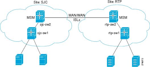
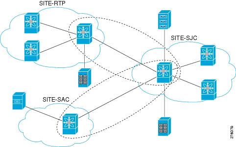


 Feedback