Cisco APIC Basic Configuration Guide, Release 1.x
Bias-Free Language
The documentation set for this product strives to use bias-free language. For the purposes of this documentation set, bias-free is defined as language that does not imply discrimination based on age, disability, gender, racial identity, ethnic identity, sexual orientation, socioeconomic status, and intersectionality. Exceptions may be present in the documentation due to language that is hardcoded in the user interfaces of the product software, language used based on RFP documentation, or language that is used by a referenced third-party product. Learn more about how Cisco is using Inclusive Language.
- Updated:
- December 4, 2015
Chapter: ACI Fabric Layer 3 Outside Connectivity
- Layer 3 Workflows
- Guidelines for Configuring a BGP Layer 3 Outside Network Connection
- Configuring a Tenant Layer 3 Outside Network Connection
- Shared Services Contracts Usage
- Shared Layer 3 Out
- Neighbor Discovery
- Configuring a Routing Control Protocol Using Import and Export Controls
- ACI Transit Routing
- Transit Routing Use Cases
- Transit Routing Overview
- Route Distribution Within the ACI Fabric
- External Layer 3 Outside Connection Types
- Supported Transit Combination Matrix
- OSPF Layer 3 Outside Connections
- EIGRP Layer 3 Outside Connections
- BGP Protocol Peering to External BGP Speakers
- Transit Route Control
- ACI Route Redistribution
- Controls Enabled for Subnets Configured under the Layer 3 Outside Network Instance Profile
- Advertising Tenant BD Subnets Outside the Fabric
- Tenant EPG to Layer 3 Outside Contract
- Advertising a Default Route
- Route Control Profile Policies
- Security Import Policies
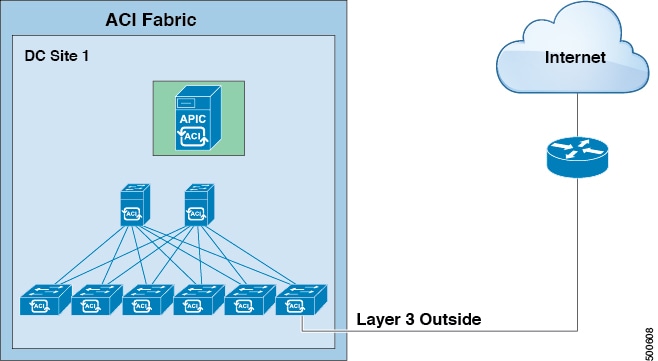
ACI Fabric Layer 3
Outside Connectivity
This chapter contains the following sections:
- Layer 3 Workflows
- Guidelines for Configuring a BGP Layer 3 Outside Network Connection
- Configuring a Tenant Layer 3 Outside Network Connection
- Shared Services Contracts Usage
- Shared Layer 3 Out
- Neighbor Discovery
- Configuring a Routing Control Protocol Using Import and Export Controls
- ACI Transit Routing
- Common Pervasive Gateway
Layer 3 Workflows
ACI Layer 3 Outside Network Workflows
This workflow provides an overview of the steps required to configure a Layer 3 outside network connection.
1. Prerequisites
Configure a Layer 3 Outside Network
Choose which of these management access scenarios you will use:
- For a Layer 3 Outside that will be consumed within a single tenant, follow the instructions for configuring BGP or OSPF.
- For a Layer 3 Outside that will be consumed (shared) among multiple tenants, follow "Layer 3 Outside guidelines.
- For Layer 3 Outside transit routing uses cases, follow ACI transit routing instructions.
Recommended topics
For additional information, see the following topics:
Guidelines for Configuring a BGP Layer 3 Outside Network Connection
When configuring a BGP external routed network, follow these guidelines:
-
Whenever a router ID is created on a leaf switch, it creates an internal loopback address. When setting up a BGP connection on a leaf switch, your router ID cannot be the same as the interface IP address as it is not supported on the ACI leaf switch. The router ID must be a different address in a different subnet. On the external Layer 3 device, the router ID can be the loopback address or an interface address. Ensure that the route to leaf router ID is present in the routing table of the the Layer3 device either through static route or OSPF configuration. Also, when setting up the BGP neighbor on a Layer 3 device, the peer IP address that is used must be the router ID of the leaf switch.
-
While configuring two external Layer 3 networks with BGP on the same node, loopback addresses must be explicitly defined. Failing to follow this guideline can prevent BGP from being established.
-
By definition, the router ID is a loopback interface. To change the router ID and assign a different address for loopback, you must create a loopback interface policy. (The loopback policy can be configured as one for each address family, IPv4 and IPv6.) If you do not wish to create a loopback policy, then you can enable a router ID loopback which is enabled by default. If the router ID loopback is disabled, no loopback is created for the specific Layer 3 outside on which it is deployed.
-
This configuration task is applicable for iBGP and eBGP. If the BGP configuration is on a loopback address then it can be an iBGP session or a multi-hop eBGP session. If the peer IP address is for a physical interface where the BGP peer is defined, then the physical interface is used.
-
The user must configure an IPv6 address to enable peering over loopback using IPv6.
-
The autonomous system feature can only be used for eBGP peers. It enables a router to appear to be a member of a second autonomous system (AS), in addition to its real AS. Local AS allows two ISPs to merge without modifying peering arrangements. Routers in the merged ISP become members of the new autonomous system but continue to use their old AS numbers for their customers.
-
Starting with release 1.2(1x), tenant networking protocol policies for BGP l3extOut connections can be configured with a maximum prefix limit that enables monitoring and restricting the number of route prefixes received from a peer. Once the max prefix limit is exceeded, a log entry can be recorded, further prefixes can be rejected, the connection can be restarted if the count drops below the threshold in a fixed interval, or the connection is shut down. Only one option can be used at a time. The default setting is a limit of 20,000 prefixes, after which new prefixes are rejected. When the reject option is deployed, BGP accepts one more prefix beyond the configured limit and the APIC raises a fault.

Note
When you configure Layer 3 Outside (L3Out) connections to external routers, it is critical that the MTU be set appropriately on both sides. On some platforms, such as ACI, Cisco NX-OS, and Cisco IOS, the configurable MTU value takes into account packet headers (resulting in a max packet size to be set as 9000 bytes), whereas other platforms such as IOS-XR configure the MTU value exclusive of packet headers (resulting in a max packet size of 8986 bytes). For the appropriate MTU values for each platform, see the relevant configuration guides. Cisco highly recommends you test the MTU using CLI-based commands. For example, on the Cisco NX-OS CLI, use a command such as ping 1.1.1.1 df-bit packet-size 9000 source-interface ethernet 1/1
- BGP Connection Types and Loopback Guidelines
- Configuring BGP External Routed Network Using the GUI
- Configuring BGP External Routed Network Using the REST API
- Configuring BGP External Routed Network Using the NX-OS Style CLI
BGP Connection Types and Loopback Guidelines
For BGP connection types and loopback set up requirements, follow these guidelines:
-
When a router ID is created for a node, a loopback interface with the same IP address as the router ID is also created. This is the default behavior but can be overridden when configuring the router ID.
-
The IP address configured for the router ID should be a different address in a different subnet from any other IP address configured on the node.
-
The loopback interface with the router ID IP address can be used for peering with an external router if there is only one external BGP peer per node. When peering with multiple BGP peers on the same node, the router ID loopback address must not be used. An explicit loopback interface policy per BGP peer must be used.
-
A loopback interface policy is not required when peering with an external router on a directly connected network.
-
When peering to an external router with a loopback interface (iBGP or eBGP multi-hop) a static route or OSPF route is required to reach the remote peer loopback address.
-
For BGP, the loopback creation is selected by default. When it is selected, the loopack is used as the source interface to establish BGP sessions. However, to establish eBGP over a physical interface, the administrator must not create loopback.
|
BGP Connection Type |
Loopback required |
Loopback same as Router ID |
Static/OSPF route required |
|---|---|---|---|
|
iBGP direct |
No |
Not applicable |
No |
|
iBGP loopback peering |
Yes, a separate loopback per BGP peer |
No, if multiple Layer 3 out are on the same node |
Yes |
|
eBGP direct |
No |
Not applicable |
No |
|
eBGP loopback peering (multi-hop) |
Yes, a separate loopback per BGP peer |
No, if multiple Layer 3 out are on the same node |
Yes |
Configuring BGP External Routed Network Using the GUI
The tenant, VRF, and bridge domain where you configure the BGP external routed network is already created.
Configuring BGP External Routed Network Using the REST API
The tenant where you configure the BGP external routed network is already created.
Example: <l3extOut descr="" dn="uni/tn-t1/out-l3out-bgp" enforceRtctrl="export" name="l3out-bgp" ownerKey="" ownerTag="" targetDscp="unspecified"> <l3extRsEctx tnFvCtxName="ctx3"/> <l3extLNodeP configIssues="" descr="" name="l3extLNodeP_1" ownerKey="" ownerTag="" tag="yellow-green" targetDscp="unspecified"> <l3extRsNodeL3OutAtt rtrId="1.1.1.1" rtrIdLoopBack="no" tDn="topology/pod-1/node-101"/> <l3extLIfP descr="" name="l3extLIfP_2" ownerKey="" ownerTag="" tag="yellow-green"> <l3extRsNdIfPol tnNdIfPolName=""/> <l3extRsIngressQosDppPol tnQosDppPolName=""/> <l3extRsEgressQosDppPol tnQosDppPolName=""/> <l3extRsPathL3OutAtt addr="3001::31:0:1:2/120" descr="" encap="vlan-3001" encapScope="local" ifInstT="sub-interface" llAddr="::" mac="00:22:BD:F8:19:FF" mode="regular" mtu="inherit" tDn="topology/pod-1/paths-101/pathep-[eth1/8]" targetDscp="unspecified"> <bgpPeerP addr="3001::31:0:1:0/120" allowedSelfAsCnt="3" ctrl="send-com,send-ext-com" descr="" name="" peerCtrl="bfd" privateASctrl="remove-all,remove-exclusive,replace-as" ttl="1" weight="1000"> <bgpRsPeerPfxPol tnBgpPeerPfxPolName=""/> <bgpAsP asn="3001" descr="" name=""/> </bgpPeerP> </l3extRsPathL3OutAtt> </l3extLIfP> <l3extLIfP descr="" name="l3extLIfP_1" ownerKey="" ownerTag="" tag="yellow-green"> <l3extRsNdIfPol tnNdIfPolName=""/> <l3extRsIngressQosDppPol tnQosDppPolName=""/> <l3extRsEgressQosDppPol tnQosDppPolName=""/> <l3extRsPathL3OutAtt addr="31.0.1.2/24" descr="" encap="vlan-3001" encapScope="local" ifInstT="sub-interface" llAddr="::" mac="00:22:BD:F8:19:FF" mode="regular" mtu="inherit" tDn="topology/pod-1/paths-101/pathep-[eth1/8]" targetDscp="unspecified"> <bgpPeerP addr=“31.0.1.0/24" allowedSelfAsCnt="3" ctrl="send-com,send-ext-com" descr="" name="" peerCtrl="" privateASctrl="remove-all,remove-exclusive,replace-as" ttl="1" weight="100"> <bgpRsPeerPfxPol tnBgpPeerPfxPolName=""/> <bgpLocalAsnP asnPropagate="none" descr="" localAsn="200" name=""/> <bgpAsP asn="3001" descr="" name=""/> </bgpPeerP> </l3extRsPathL3OutAtt> </l3extLIfP> </l3extLNodeP> <l3extRsL3DomAtt tDn="uni/l3dom-l3-dom"/> <l3extRsDampeningPol af="ipv6-ucast" tnRtctrlProfileName="damp_rp"/> <l3extRsDampeningPol af="ipv4-ucast" tnRtctrlProfileName="damp_rp"/> <l3extInstP descr="" matchT="AtleastOne" name="l3extInstP_1" prio="unspecified" targetDscp="unspecified"> <l3extSubnet aggregate="" descr="" ip="130.130.130.0/24" name="" scope="import-rtctrl"> </l3extSubnet> <l3extSubnet aggregate="" descr="" ip="130.130.131.0/24" name="" scope="import-rtctrl"/> <l3extSubnet aggregate="" descr="" ip="120.120.120.120/32" name="" scope="export-rtctrl,import-security"/> <l3extSubnet aggregate="" descr="" ip="3001::130:130:130:100/120" name="" scope="import-rtctrl"/> </l3extInstP> <bgpExtP descr=""/> </l3extOut> <rtctrlProfile descr="" dn="uni/tn-t1/prof-damp_rp" name="damp_rp" ownerKey="" ownerTag="" type="combinable"> <rtctrlCtxP descr="" name="ipv4_rpc" order="0"> <rtctrlScope descr="" name=""> <rtctrlRsScopeToAttrP tnRtctrlAttrPName="act_rule"/> </rtctrlScope> </rtctrlCtxP> </rtctrlProfile> <rtctrlAttrP descr="" dn="uni/tn-t1/attr-act_rule" name="act_rule"> <rtctrlSetDamp descr="" halfLife="15" maxSuppressTime="60" name="" reuse="750" suppress="2000" type="dampening-pol"/> </rtctrlAttrP> |
Configuring BGP External Routed Network Using the NX-OS Style CLI
Example: apic1(config-leaf)#template route-profile damp_rp tenant t1 This template will be available on all leaves where tenant t1 has a VRF deployment apic1(config-leaf-template-route-profile)#set dampening 15 750 2000 60 apic1(config-leaf-template-route-profile)#exit apic1(config-leaf)# apic1(config-leaf)#router bgp 100 apic1(config-bgp)#vrf member tenant t1 vrf ctx3 apic1(config-leaf-bgp-vrf)# neighbor 32.0.1.0/24 l3out l3out-bgp apic1(config-leaf-bgp-vrf-neighbor)#update-source ethernet 1/16.401 apic1(config-leaf-bgp-vrf-neighbor)#address-family ipv4 unicast apic1(config-leaf-bgp-vrf-neighbor-af)#weight 400 apic1(config-leaf-bgp-vrf-neighbor-af)#exit apic1(config-leaf-bgp-vrf-neighbor)#remote-as 65001 apic1(config-leaf-bgp-vrf-neighbor)#private-as-control remove-exclusive apic1(config-leaf-bgp-vrf-neighbor)#private-as-control remove-exclusive-all apic1(config-leaf-bgp-vrf-neighbor)#private-as-control remove-exclusive-all-replace-as apic1(config-leaf-bgp-vrf-neighbor)#exit apic1(config-leaf-bgp-vrf)# address-family ipv4 unicast apic1(config-leaf-bgp-vrf-af)#inherit bgp dampening damp_rp This template will be inherited on all leaves where VRF ctx3 has been deployed apic1(config-leaf-bgp-vrf-af)#exit apic1(config-leaf-bgp-vrf)# address-family ipv6 unicast apic1(config-leaf-bgp-vrf-af)#inherit bgp dampening damp_rp This template will be inherited on all leaves where VRF ctx3 has been deployed apic1(config-leaf-bgp-vrf-af)#exit |
Configuring a Tenant Layer 3 Outside Network Connection
This topic provides a typical example of how to configure a Layer 3 Outside for tenant networks when using Cisco APIC.
Note | When you configure Layer 3 Outside (L3Out) connections to external routers, it is critical that the MTU be set appropriately on both sides. On some platforms, such as ACI, Cisco NX-OS, and Cisco IOS, the configurable MTU value takes into account packet headers (resulting in a max packet size to be set as 9000 bytes), whereas other platforms such as IOS-XR configure the MTU value exclusive of packet headers (resulting in a max packet size of 8986 bytes). For the appropriate MTU values for each platform, see the relevant configuration guides. Cisco highly recommends you test the MTU using CLI-based commands. For example, on the Cisco NX-OS CLI, use a command such as ping 1.1.1.1 df-bit packet-size 9000 source-interface ethernet 1/1 |
- Configuring a Layer 3 Outside for Tenant Networks Using the GUI
- Configuring Layer 3 Outside for Tenant Networks Using the REST API
- Configuring a Layer 3 Outside for Tenant Networks Using the NX-OS Style CLI
Configuring a Layer 3 Outside for Tenant Networks Using the GUI
The external routed network configured in the example can also be extended to support IPv4. Both IPv4 and IPv6 routes can be advertised to and learned from the external routed network.
| Step 1 | On the menubar, click TENANTS. | ||
| Step 2 | In the
Navigation pane, expand the
and perform the following actions:
| ||
| Step 3 | Expand
Interface Profiles, and perform the following
actions:
| ||
| Step 4 | In the Create Node Profile dialog box, click OK. | ||
| Step 5 | In the Create Routed Outside dialog box, click Next. | ||
| Step 6 | In the External EPG Networks area, expand External EPG Networks. | ||
| Step 7 | In the Create External Networks dialog box, in the Name field, enter a name for the external network. | ||
| Step 8 | Expand Subnet. | ||
| Step 9 | In the Create Subnet dialog box, perform the following actions: | ||
| Step 10 | In the
Create
External Network dialog box, perform the following actions:
| ||
| Step 11 | In the Create Routed Outside dialog box, click Finish. | ||
| Step 12 | In the Navigation pane, under and choose the Bridge_Domain_name. | ||
| Step 13 | In the Navigation pane, choose the BD you created. In the Work pane, choose the L3 Configurations tab and in the Associated L3 Outs field, associate the desired L3 Out and choose the desired L3 Out for Route Profile. Click Update. If the L3 Out is static, you are not required to choose any settings. | ||
| Step 14 |
|
Configuring Layer 3 Outside for Tenant Networks Using the REST API
The external routed network configured in the example can also be extended to support IPv4. Both IPv4 and IPv6 routes can be advertised to and learned from the external routed network.
Example:
<l3extOut name="L3Out1" enforceRtctrl="import,export">
            <l3extRsL3DomAtt tDn="uni/l3dom-l3DomP"/>
        <l3extLNodeP name="LNodeP1" >
            <l3extRsNodeL3OutAtt rtrId="1.2.3.4" tDn="topology/pod-1/node-101">
                <l3extLoopBackIfP addr="10.10.11.1" />
                <l3extLoopBackIfP addr="2000::3" />
            </l3extRsNodeL3OutAtt>
            <l3extLIfP  name="IFP1" >
                <l3extRsPathL3OutAtt addr="10.11.12.10/24"  ifInstT="l3-port"  tDn="topology/pod-1/paths-103/pathep-[eth1/17]" />
            </l3extLIfP>
            <l3extLIfP  name="IFP2" >
                <l3extRsPathL3OutAtt addr="2001::3/64"  ifInstT="l3-port"  tDn="topology/pod-1/paths-103/pathep-[eth1/17]" />
            </l3extLIfP>
        </l3extLNodeP>
        <l3extRsEctx tnFvCtxName="VRF1"/>
        <l3extInstP name="InstP1" >
            <l3extSubnet ip="192.168.1.0/24" scope="import-security" aggregate=""/>
            <l3extSubnet ip="0.0.0.0/0" scope="export-rtctrl,import-rtctrl,import-security" aggregate="export-rtctrl,import-rtctrl"/>
            <l3extSubnet ip="192.168.2.0/24" scope="export-rtctrl" aggregate=""/>
            <l3extSubnet ip="::/0" scope="import-rtctrl,import-security" aggregate="import-rtctrl"/>
            <l3extSubnet ip="2001:17a::/64" scope="export-rtctrl" aggregate=""/>
        </l3extInstP>
    </l3extOut>
|
Configuring a Layer 3 Outside for Tenant Networks Using the NX-OS Style CLI
The following steps describe how to configure a Layer 3 outside network for tenant networks as well as how to configure Layer 3 outside networks for individual protocols.
Configure a tenant and VRF.
| Step 1 | The following
example shows how to deploy a node and L3 port for tenant VRF external L3
connectivity using the NX-OS CLI:
Example: apic1# configure apic1(config)# leaf 101 apic1(config-leaf)# vrf context tenant exampleCorp vrf v1 apic1(config-leaf-vrf)# router-id 1.2.3.4 apic1(config-leaf-vrf)# ip route 21.1.1.1/32 32.1.1.1 apic1(config-leaf-vrf)# ipv6 route 5001::1/128 6002::1 preferred apic1(config-leaf-vrf)# exit apic1(config-leaf)# interface eth 1/1 apic1(config-leaf-if)# vlan-domain member dom1 apic1(config-leaf-if)# no switchport apic1(config-leaf-if)# vrf member tenant exampleCorp vrf v1 apic1(config-leaf-if)# ip address 10.1.1.1/24 apic1(config-leaf-if)# ip address 11.1.1.1/24 secondary apic1(config-leaf-if)# ipv6 address 2001::1/64 preferred apic1(config-leaf-if)# ipv6 link-local fe80::1 apic1(config-leaf-if)# mac-address 00:44:55:66:55::01 apic1(config-leaf-if)# mtu 4470 |
| Step 2 | The following
shows how to configure a route map using the NX-OS CLI:
Example: apic1(config)# leaf 101 apic1(config-leaf)# vrf context tenant exampleCorp vrf v1 apic1(config-leaf-vrf)# router-id 1.2.3.4 apic1(config-leaf-vrf)# route-map rtMap1 apic1(config-leaf-vrf)#scope global apic1(config-leaf-vrf-route-map)# ip prefix-list list1 permit 13.13.13.0/24 apic1(config-leaf-vrf-route-map)# match prefix-list list1 apic1(config-leaf-vrf-route-map-match)# set metric 128 apic1(config-leaf-vrf-route-map-match)# set metric-type type-2 apic1(config-leaf-vrf-route-map-match)# set local-preference 64 apic1(config-leaf-vrf-route-map-match)# set community extended 20:22 additive apic1(config-leaf-vrf-route-map-match)# set tag 1111 apic1(config-leaf-vrf-route-map-match)# contract provider prov1 apic1(config-leaf-vrf-route-map-match)# exit apic1(config-leaf-vrf-route-map)# match bridge-domain bd1 |
| Step 3 | The following
shows how to a configure Layer 3 outside network for the BGP protocol:
Example: apic1# configure apic1(config)# leaf 101 apic1(config-leaf)# router bgp 100 apic1(config-bgp)# vrf member tenant exampleCorp vrf v100 apic1(config-leaf-bgp-vrf)# neighbor 192.0.2.10/32 apic1(config-leaf-bgp-vrf)# neighbor 192.0.2.11/32 apic1(config-leaf-bgp-vrf-neighbor)# address-family ipv4 unicast apic1(config-leaf-bgp-vrf-neighbor-af)# maximum-prefix 10 threshold 10 action restart restart-time 10 apic1(config-leaf-bgp-vrf-neighbor-af)# exit apic1(config-leaf-bgp-vrf-neighbor)# remote-as 200 apic1(config-leaf-bgp-vrf-neighbor)# update-source ethernet 1/1 apic1(config-leaf-bgp-vrf-neighbor)# route-map rtMap1 out apic1(config-leaf-bgp-vrf-neighbor)# exit To configure route-summarization apic1(config)# leaf 101 apic1(config-leaf)# router bgp 100 apic1(config-bgp)# vrf member tenant exampleCorp vrf v100 apic1(config-leaf-bgp-vrf)# aggregate-address 192.0.2.0/28 as-set |
| Step 4 | The following
shows how to configure a Layer 3 outside network for the OSPF protocol:
Example: apic1# configure apic1(config)# leaf 102 apic1(config-leaf)# router ospf default apic1(config-leaf-ospf)# vrf member tenant exampleCorp vrf v100 apic1(config-leaf-ospf-vrf)# area 0 nssa apic1(config-leaf-ospf-vrf)# area 17 stub apic1(config-leaf-ospf-vrf)# area 17 default-cost 20 apic1(config-leaf-ospf-vrf)# area 17 route-map ospf-to-eigrp out apic1(config-leaf-ospf-vrf)# area 17 loopback 192.0.20.11/32 apic1(config-leaf-ospf-vrf)# inherit ipv4 rtMap1 vrfTemplate2 apic1(config-leaf-ospf-vrf)# exit apic1(config-leaf-ospf)# exit apic1(config-leaf)# interface eth 1/3 apic1(config-leaf-if)# ip router ospf default area 17 apic1(config-leaf-if)# ip ospf inherit interface-policy ifPolicy3 tenant exampleCorp apic1(config-leaf-if)# ip ospf authentication md5 apic1(config-leaf-if)# ip ospf authentication-key c1$c0123 |
| Step 5 | The following
shows how to configure a Layer 3 outside network for the EIGRP protocol:
Example: apic1# configure apic1(config)# leaf 101 apic1(config-leaf)# router eigrp default apic1(config-eigrp)# vrf member tenant exampleCorp vrf v100 apic1(config-eigrp-vrf)# autonomous-system 300 apic1(config-eigrp-vrf)# exit apic1(config-eigrp)# exit apic1(config-leaf)# interface ethernet 1/21 apic1(config-leaf-if)# no switchport 5 apic1(config-leaf-if)# vlan-domain member dom1 apic1(config-leaf-if)# vrf member tenant exampleCorp vrf v100 apic1(config-leaf-if)# ip address 181.12.12.1/24 apic1(config-leaf-if)# ip router eigrp default apic1(config-leaf-if)# ip distribute-list eigrp default route-map rMapT5 out distribute list will be updated on all EIGRP interfaces on node 1021 VRF exampleCorp/v100 apic1(config-leaf-if)# ip hello-interval eigrp default 5 apic1(config-leaf-if)# ip hold-interval eigrp default 10 apic1(config-leaf-if)# ip next-hop-self eigrp default apic1(config-leaf-if)# ip passive-interface eigrp default apic1(config-leaf-if)# ip split-horizon eigrp default apic1(config-leaf-if)# inherit eigrp ip interface-policy ifTemplate5 |
| Step 6 | The following
shows how to configure an external-L3 EPG and deploy it on a leaf switch:
Example: apic1# configure apic1(config)# tenant exampleCorp # CONFIGURE EXTERNAL L3 EPG apic1(config-tenant)# external-l3 epg epgExtern1 apic1(config-tenant-l3ext-epg)# vrf member v1 apic1(config-tenant-l3ext-epg)# match ip 192.0.20.0/24 apic1(config-tenant-l3ext-epg)# match ipv6 2001::1/64 apic1(config-tenant-l3ext-epg)# set qos-class level1 apic1(config-tenant-l3ext-epg)# set dscp af31 apic1(config-tenant-l3ext-epg)# contract consumer cConsumer1 apic1(config-tenant-l3ext-epg)# contract provider cProvider1 apic1(config-tenant-l3ext-epg)# contract deny cDeny1 apic1(config-tenant-l3ext-epg)# exit apic1(config-tenant)# exit # DEPLOY EXTERNAL L3 EPG ON A LEAF apic1(config)# leaf 101 apic1(config-leaf)# vrf context tenant exampleCorp vrf |
Shared Services Contracts Usage
Shared services enable communications across tenants while preserving the isolation and security policies of the tenants. A routed connection to an external network is an example of a shared service that multiple tenants use.
Follow these guidelines when configuring shared services contracts.
-
For shared services that export subnets to different contexts (VRFs), the subnet must be configured under an EPG, and the scope must be set to advertised externally and shared between VRFs.
-
Contracts are not needed for inter-bridge domain traffic when a private network is unenforced.
-
Contracts are needed for shared service inter-context (VRF) traffic even when a context (VRF) is unenforced.
-
The context (VRF) of a provider EPG cannot be in unenforced mode while providing a shared service.
-
A shared service is supported only with non-overlapping and non-duplicate subnets. When configuring subnets for shared services, follow these guidelines:
-
Configure the subnet for a shared service provider under the EPG, not under the bridge domain.
-
Subnets configured under an EPG that share the same context must be disjointed and must not overlap.
-
Subnets leaked from one context to another must be disjointed and must not overlap.
-
Subnets leaked from multiple consumer networks into a context or vice versa must be disjointed and must not overlap.
Note
If two consumers are mistakenly configured with the same subnet, recover from this condition by removing the subnet configuration for both then reconfigure the subnets correctly.
-
-
Do not configure a shared service with AnyToProv in the provider context. The APIC rejects this configuration and raises a fault.
-
When a contract is configured between in-band and out-of-band EPGs, the following restrictions apply:
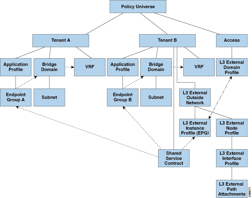
Shared Layer 3 Out
A shared Layer 3 Out configuration provides routed connectivity to external networks as a shared service. An l3extInstP EPG provides routed connectivity to external networks. It can be can be provisioned as a shared service in any tenant (user, common, infra, or mgmt.). Prior to release 1.2(1x), this configuration was only supported in the user and common tenants. An EPG in any tenant can use a shared services contract to connect with an l3extInstP EPG regardless of where in the fabric that l3extInstP EPG is provisioned. This simplifies the provisioning of routed connectivity to external networks; multiple tenants can share a single l3extInstP EPG for routed connectivity to external networks. Sharing an l3extInstP EPG is more efficient because it consumes only one session on the switch regardless of how many EPGs use the single shared l3extInstP EPG.
Note | All switches that will use l3extInstP EPG shared service contracts require the hardware and software support available starting with the APIC 1.2(1x) and switch 11.2(1x) releases. Refer to the Firmware Management Guide and Release Notes documentation for more details. |
Take note of the following guidelines and limitations for shared Layer 3 Out configurations::
-
No tenant limitations: Tenants A and B can be any kind of tenant (user, common, infra, mgmt.). The shared l3extInstP EPG does not have to be in tenant common.
-
Flexible placement of EPGs: EPG A and EPG B in the illustration above are in different tenants. EPG A and EPG B could use the same bridge domain and context, but they are not required to do so. EPG A and EPG B are in different bridge domains and different contexts but still share the same l3extInstP EPG.
-
A subnet can be private, public, or shared. A subnet that is to be leaked into a consumer or provider EPG of a Layer 3 External Outside Network must be set to shared. A subnet that is to be exported to a Layer 3 External Outside Network must be set to public.
-
The shared service contract is exported from the tenant that contains the l3extInstP EPG that provides shared Layer 3 Out service. The shared service contract is imported into the tenants that contain the EPGs that consume the shared service.
-
Do not use taboo contracts with a shared L3 out; this configuration is not supported.
-
The l3extInstP as a shared service provider is supported, but only with non l3extInstP consumers (where Layer3Out EPg = l3extInstP).
-
Transit routing is not supported with shared services. In other words, two Layer3 Outs in different VRFs cannot communicate with each other using the shared services feature.
-
Traffic Flap: When an l3instP EPG is configured with an external subnet of 0.0.0.0/0 with the scope property of the l3instP subnet set to shared route control (shared-rctrl), or shared security (shared-security), the context (VRF) is redeployed with a global pcTag. This will flap all the external traffic in that VRF (because the VRF is redeployed with a global pcTag).
-
Prefixes for a shared Layer 3 out must to be unique. Multiple shared Layer 3 Out configurations with the same prefix in the same context (VRF) will not work. Be sure that the external subnets (external prefixes) getting leaked into a VRF are be unique (the same external subnet cannot belong to multiple l3instPs). A Layer 3 outside configuration (for example, named L3Out1) with prefix1 and a second Layer 3 outside configuration (for example, named L3Out2) also with prefix1 belonging to the same context (VRF) will not work (because only 1 pcTag will be deployed).
-
Traffic not permitted: Traffic is not permitted when an invalid configuration sets the scope of the external subnet to shared route control (shared-rtctrl) as a subset of a subnet that is set to shared security(shared-security). For example, the following configuration is invalid:
In this case, traffic coming in on a non-border leaf with a destination IP of 10.1.1.1 will get dropped since prefixes 10.1.1.0/24 and 10.1.2.0/24 are installed with a drop rule. Traffic is not permitted. Such traffic can be enabled by revising the configuration to use the shared-rtctrl prefixes as shared-security prefixes as well.
-
Inadvertent traffic flow: Prevent inadvertent traffic flow by avoiding the following configuration scenarios:
-
Case 1 configuration details:
-
A Layer 3 outside configuration (for example, named L3Out1) with context (VRF) 1 is called provider1.
-
A second Layer 3 outside configuration (for example, named L3Out2) with context (VRF) 2 is called provider2.
-
L3Out1 VRF1 advertises a default route to the Internet = 0.0.0.0/0 = shared-rtctrl, shared-security.
-
L3Out2 VRF2 advertises specific subnets to DNS and NTP = 192.0.0.0/8 = shared-rtctrl.
-
L3Out2 VRF2 has specific subnets 192.1.0.0/16 = shared-security.
-
Variation A: EPG Traffic Goes to Multiple Contexts (VRFs).
-
Variation B: An EPG conforms to allow_all contract of second shared Layer 3 out.
-
-
Case 2 configuration details:
-
A Layer 3 out instance profile (l3instP) has one shared prefix and other non-shared prefixes.
-
Traffic coming in with src = non-shared is allowed to go to the EPG
-
-
Neighbor Discovery
The IPv6 Neighbor Discovery (ND) protocol is responsible for address autoconfiguration of nodes, discovery of other nodes on the link, determining the link-layer addresses of other nodes, duplicate address detection, finding available routers and DNS servers, address prefix discovery, and maintaining reachability information about the paths to other active neighbor nodes.
ND-specific Neighbor Solicitation/Neighbor Advertisement (NS/NA) and Router Solicitation/Router Advertisement (RS/RA) packet types are supported on all ACI fabric Layer 3 interfaces, including physical, L3 Sub-if, and SVI (external and pervasive). RS/RA packets are used for autoconfiguration for all L3 interfaces but are only configurable for pervasive SVIs. ACI bridge domain ND always operates in flood mode; unicast mode is not supported.
The ACI fabric ND support includes the following:
-
Interface policies (nd:IfPol) control ND timers and behavior for NS/NA messages.
-
ND prefix policies (nd:PfxPol) controls RA messages.
-
Configuration of IPv6 subnets for ND (fv:Subnet).
-
ND interface policies for external networks.
-
Configurable ND subnets for external networks, and arbitrary subnet configurations for pervasive bridge domains are not supported.
Configuration options include the following:
- Creating the Tenant, VRF, and Bridge Domain with IPv6 Neighbor Discovery Using the Advanced GUI
- Creating the Tenant, VRF, and Bridge Domain with IPv6 Neighbor Discovery Using the REST API
- Configuring a Tenant, VRF, and Bridge Domain with IPv6 Neighbor Discovery Using the CLI
Creating the Tenant, VRF, and Bridge Domain with IPv6 Neighbor Discovery Using the Advanced GUI
This task shows how to create a tenant, a VRF, and a bridge domain (BD) within which two different types of Neighbor Discovery (ND) policies are created. They are ND interface policy and ND prefix policy. While ND interface policies are deployed under BDs, ND prefix policies are deployed for individual subnets. Each BD can have its own ND interface policy . The ND interface policy is deployed on all IPv6 interfaces by default. In Cisco APIC, there is already an ND interface default policy available to use. If desired, you can create a custom ND interface policy to use instead. The ND prefix policy is on a subnet level. Every BD can have multiple subnets, and each subnet can have a different ND prefix policy.
| Step 1 | On the menu bar, click . | ||
| Step 2 | In the Create Tenant dialog box, perform the following tasks: | ||
| Step 3 | In the Navigation pane, expand . In the Work pane, drag the VRF icon to the canvas to open the Create VRF dialog box, and perform the following actions: | ||
| Step 4 | In the Networking area, drag the BD icon to the canvas while connecting it to the VRF icon. In the Create Bridge Domain dialog box that displays, perform the following actions: | ||
| Step 5 | In the Subnet Control field, ensure that the ND RA Prefix check box is checked. | ||
| Step 6 | In the
ND
Prefix policy field drop-down list, click
Create
ND RA Prefix Policy.
| ||
| Step 7 | In the
Create
ND RA Prefix Policy dialog box, perform the following actions:
| ||
| Step 8 | In the ND policy field drop-down list, click Create ND Interface Policy and perform the following tasks: | ||
| Step 9 | Click
OK to complete the bridge domain configuration.
Similarly you can create additional subnets with different prefix policies as required. A subnet with an IPv6 address is created under the BD and an ND prefix policy has been associated with it. |
Creating the Tenant, VRF, and Bridge Domain with IPv6 Neighbor Discovery Using the REST API
Example: <fvTenant descr="" dn="uni/tn-ExampleCorp" name="ExampleCorp" ownerKey="" ownerTag="">
<ndIfPol name="NDPol001" ctrl="managed-cfg” descr="" hopLimit="64" mtu="1500" nsIntvl="1000" nsRetries=“3" ownerKey="" ownerTag="" raIntvl="600" raLifetime="1800" reachableTime="0" retransTimer="0"/>
<fvCtx descr="" knwMcastAct="permit" name="pvn1" ownerKey="" ownerTag="" pcEnfPref="enforced">
</fvCtx>
<fvBD arpFlood="no" descr="" mac="00:22:BD:F8:19:FF" multiDstPktAct="bd-flood" name="bd1" ownerKey="" ownerTag="" unicastRoute="yes" unkMacUcastAct="proxy" unkMcastAct="flood">
<fvRsBDToNdP tnNdIfPolName="NDPol001"/>
<fvRsCtx tnFvCtxName="pvn1"/>
<fvSubnet ctrl="nd" descr="" ip="34::1/64" name="" preferred="no" scope="private">
<fvRsNdPfxPol tnNdPfxPolName="NDPfxPol001"/>
</fvSubnet>
<fvSubnet ctrl="nd" descr="" ip="33::1/64" name="" preferred="no" scope="private">
<fvRsNdPfxPol tnNdPfxPolName="NDPfxPol002"/>
</fvSubnet>
</fvBD>
<ndPfxPol ctrl="auto-cfg,on-link" descr="" lifetime="1000" name="NDPfxPol001" ownerKey="" ownerTag="" prefLifetime="1000"/>
<ndPfxPol ctrl="auto-cfg,on-link" descr="" lifetime="4294967295" name="NDPfxPol002" ownerKey="" ownerTag="" prefLifetime="4294967295"/>
</fvTenant>
|
Configuring a Tenant, VRF, and Bridge Domain with IPv6 Neighbor Discovery Using the CLI
| Step 1 | In the CLI,
change the directory to
/aci.
Example: admin@apic1:~> cd /aci |
| Step 2 | Configure a
neighbor discovery interface policy.
Example: admin@apic1:aci> cd tenants/ admin@apic1:tenants> mocreate ExampleCorp admin@apic1:tenants> moconfig commit admin@apic1:tenants> cd ExampleCorp/ admin@apic1:ExampleCorp> cd networking/protocol-policies/nd/ admin@apic1:nd> mocreate interface-policy NDPol001 admin@apic1:nd> moconfig commit admin@apic1:nd> cd interface-policy-NDPol001/ admin@apic1:interface-policy-NDPol001> moset mtu 1500 admin@apic1:interface-policy-NDPol001> moconfig commit admin@apic1:interface-policy-NDPol001> admin@apic1:interface-policy-NDPol001> cd ../../../private-networks/ admin@apic1:private-networks> mocreate pvn1 admin@apic1:private-networks> moconfig commit admin@apic1:pvn1> cd ../../bridge-domains/ admin@apic1:bridge-domains> mocreate bd1 admin@apic1:bridge-domains> cd bd1 admin@apic1:bd1> moset custom-mac-address 00:22:BD:F8:19:FF admin@apic1:bd1> moset nd-interface-policy NDPol001 admin@apic1:bd1> moconfig commit |
| Step 3 | Configure a
neighbor discovery prefix policy.
Example: admin@apic1:bd1> cd ../../protocol-policies/nd/
admin@apic1:nd> mocreate prefix-policy NDPfxPol001
admin@apic1:nd> cd prefix-policy-NDPfxPol001/
admin@apic1:prefix-policy-NDPfxPol001> moset valid-lifetime 1000
admin@apic1:prefix-policy-NDPfxPol001> moset preferred-lifetime 1000
admin@apic1:prefix-policy-NDPfxPol001> moconfig commit
admin@apic1:prefix-policy-NDPfxPol001> cd ../
admin@apic1:nd> mocreate prefix-policy NDPfxPol002
admin@apic1:nd> cd prefix-policy-NDPfxPol002/
admin@apic1:prefix-policy-NDPfxPol002> moset valid-lifetime 4294967295
admin@apic1:prefix-policy-NDPfxPol002> moset preferred-lifetime 4294967295
admin@apic1:prefix-policy-NDPfxPol002> moconfig commit
admin@apic1:prefix-policy-NDPfxPol002> cd ../../../bridge-domains/bd1/subnets/
admin@apic1:subnets> mocreate 34::1/64
admin@apic1:subnets> cd 34::1_64/
admin@apic1:34::1_64> moset nd-prefix-policy NDPfxPol001
admin@apic1:34::1_64> moconfig commit
admin@apic1:34::1_64> cd ../
admin@apic1:subnets> mocreate 33::1/64
admin@apic1:subnets> cd 33::1_64/
admin@apic1:33::1_64> moset nd-prefix-policy NDPfxPol002
admin@apic1:33::1_64> moconfig commit
|
Configuring a Routing Control Protocol Using Import and Export Controls
Note | When you configure Layer 3 Outside (L3Out) connections to external routers, it is critical that the MTU be set appropriately on both sides. On some platforms, such as ACI, Cisco NX-OS, and Cisco IOS, the configurable MTU value takes into account packet headers (resulting in a max packet size to be set as 9000 bytes), whereas other platforms such as IOS-XR configure the MTU value exclusive of packet headers (resulting in a max packet size of 8986 bytes). For the appropriate MTU values for each platform, see the relevant configuration guides. Cisco highly recommends you test the MTU using CLI-based commands. For example, on the Cisco NX-OS CLI, use a command such as ping 1.1.1.1 df-bit packet-size 9000 source-interface ethernet 1/1 |
- Configuring a Route Control Protocol to Use Import and Export Controls Using the GUI
- Configuring a Route Control Protocol to Use Import and Export Controls Using the REST API
- Configuring Route Control Protocol Using Import and Export Controls Using the NX-OS Style CLI
Configuring a Route Control Protocol to Use Import and Export Controls Using the GUI
This task lists steps to create import and export policies. By default, import controls are not enforced, so the import control must be manually assigned.
| Step 1 | On the menu bar, click . | ||
| Step 2 | Right click Layer3_Outside_name and click Create Route Profile. | ||
| Step 3 | In the
Create
Route Profile dialog box, perform the following actions:
| ||
| Step 4 | In the
Create
Route Control Context dialog box, perform the following actions:
| ||
| Step 5 | In the Navigation pane, choose . In the Work pane, under Properties the route profile policy and the associated action rule name are displayed. | ||
| Step 6 | In the Navigation pane, click the Layer3_Outside_name. In the Work pane, the Properties are displayed. | ||
| Step 7 | (Optional)
Click the
Route
Control Enforcement field and enter
Import
Control to enable the import policy.
The import control policy is not enabled by default but can be enabled by the user. The import control policy is supported for BGP but not for EIGRP or for OSPF. If the user enables the import control policy for an unsupported protocol, it will be automatically ignored. The export control policy is supported for BGP, EIGRP, and OSPF. | ||
| Step 8 | To create a
customized export policy, right-click
Route
Profiles, click
Create
Route Profiles, and perform the following actions:
| ||
| Step 9 | In the Navigation pane, expand , and perform the following actions: | ||
| Step 10 | Click Submit. |
Configuring a Route Control Protocol to Use Import and Export Controls Using the REST API
Example:
<l3extOut descr="" dn="uni/tn-Ten_ND/out-L3Out1" enforceRtctrl="export" name="L3Out1" ownerKey="" ownerTag="" targetDscp="unspecified">
        <l3extLNodeP descr="" name="LNodeP1" ownerKey="" ownerTag="" tag="yellow-green" targetDscp="unspecified">
            <l3extRsNodeL3OutAtt rtrId="1.2.3.4" rtrIdLoopBack="yes" tDn="topology/pod-1/node-101">
                <l3extLoopBackIfP addr="2000::3" descr="" name=""/>
            </l3extRsNodeL3OutAtt>
            <l3extLIfP descr="" name="IFP1" ownerKey="" ownerTag="" tag="yellow-green">
                <ospfIfP authKeyId="1" authType="none" descr="" name="">
                    <ospfRsIfPol tnOspfIfPolName=""/>
                </ospfIfP>
                <l3extRsNdIfPol tnNdIfPolName=""/>
                <l3extRsPathL3OutAtt addr="10.11.12.10/24" descr="" encap="unknown" ifInstT="l3-port"
llAddr="::" mac="00:22:BD:F8:19:FF" mtu="1500" tDn="topology/pod-1/paths-101/pathep-[eth1/17]" targetDscp="unspecified"/>
            </l3extLIfP>
        </l3extLNodeP>
        <l3extRsEctx tnFvCtxName="PVN1"/>
        <l3extInstP descr="" matchT="AtleastOne" name="InstP1" prio="unspecified" targetDscp="unspecified">
            <fvRsCustQosPol tnQosCustomPolName=""/>
            <l3extSubnet aggregate="" descr="" ip="192.168.1.0/24" name="" scope=""/>
        </l3extInstP>
        <ospfExtP areaCost="1" areaCtrl="redistribute,summary" areaId="0.0.0.1" areaType="nssa" descr=""/>
        <rtctrlProfile descr="" name="default-export" ownerKey="" ownerTag="">
            <rtctrlCtxP descr="" name="routecontrolpvtnw" order="3">
                <rtctrlScope descr="" name="">
                    <rtctrlRsScopeToAttrP tnRtctrlAttrPName="actionruleprofile2"/>
                </rtctrlScope>
            </rtctrlCtxP>
        </rtctrlProfile>
    </l3extOut>
|
Configuring Route Control Protocol Using Import and Export Controls Using the NX-OS Style CLI
This section describes how to create a route map using the NX-OS CLI:
| Step 1 | Import Route
control using match community, match prefix-list
Example:
apic1# configure
apic1(config)# leaf 101
    # Create community-list
apic1(config-leaf)# template community-list standard CL_1 65536:20 tenant exampleCorp
apic1(config-leaf)# vrf context tenant exampleCorp vrf v1

     #Create Route-map and use it for BGP import control.
apic1(config-leaf-vrf)# route-map bgpMap
    # Match prefix-list and set route-profile actions for the match.
apic1(config-leaf-vrf-route-map)# ip prefix-list list1 permit 13.13.13.0/24
apic1(config-leaf-vrf-route-map)# ip prefix-list list1 permit 14.14.14.0/24
apic1(config-leaf-vrf-route-map)# match prefix-list list1
apic1(config-leaf-vrf-route-map-match)# set tag 200
apic1(config-leaf-vrf-route-map-match)# set local-preference 64
    # Match community-list and set route-profile actions for the match.
apic1(config-leaf-vrf-route-map)# match community CL_1
apic1(config-leaf-vrf-route-map-match)# set metric 200
apic1(config-leaf-vrf-route-map-match)# set community extended 20:22 additive
     #Adding the route-map the protocol.
apic1(config-leaf)# router bgp 100
apic1(config-bgp)# vrf member tenant exampleCorp vrf v1
apic1(config-leaf-bgp-vrf)# neighbor 3.3.3.3
apic1(config-leaf-bgp-vrf-neighbor)# route-map bgpMap in
| ||
| Step 2 | Export Route Control using match BD, default-export route-profile
Example: # Create custom and "default-export" route-profiles apic1(config)# leaf 101 apic1(config-leaf)# vrf context tenant exampleCorp vrf v1 apic1(config-leaf-vrf)# template route-profile default-export apic1(config-leaf-vrf-template-route-profile)# set metric 256 apic1(config-leaf-vrf)# template route-profile bd-rtctrl apic1(config-leaf-vrf-template-route-profile)# set metric 128 #Create a Route-map and match on BD, prefix-list apic1(config-leaf-vrf)# route-map bgpMap apic1(config-leaf-vrf-route-map)# match bridge-domain bd1 apic1(config-leaf-vrf-route-map-match)#exit apic1(config-leaf-vrf-route-map)# match prefix-list p1 apic1(config-leaf-vrf-route-map-match)#exit apic1(config-leaf-vrf-route-map)# match bridge-domain bd2 apic1(config-leaf-vrf-route-map-match)# inherit route-profile bd-rtctrl
|
ACI Transit Routing
The ACI fabric supports transit routing, which enables border routers to perform bidirectional redistribution with other routing domains. Unlike the stub routing domains of earlier releases of the ACI Fabric that block transit redistribution, bidirectional redistribution passes routing information from one routing domain to another. Such redistribution lets the ACI fabric provide full IP connectivity between different routing domains. Doing so can also provide redundant connectivity by enabling backup paths between routing domains.
Design transit redistribution policies that avoid sub-optimal routing or the more serious problem of routing loops. Typically, transit redistribution does not preserve the original topology and link-state information and redistributes external routes in distance-vector fashion (routes are advertised as vector prefixes and associated distances even with link-state protocols). Under these circumstances, the routers can inadvertently form routing loops that fail to deliver packets to their destination.
Transit Routing Use Cases
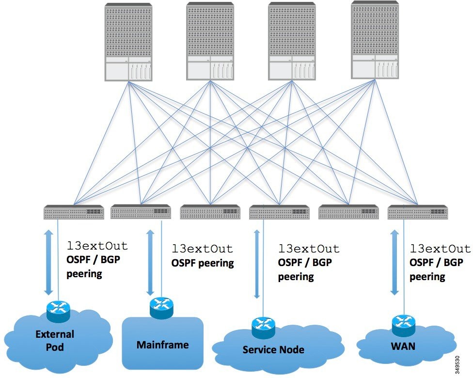
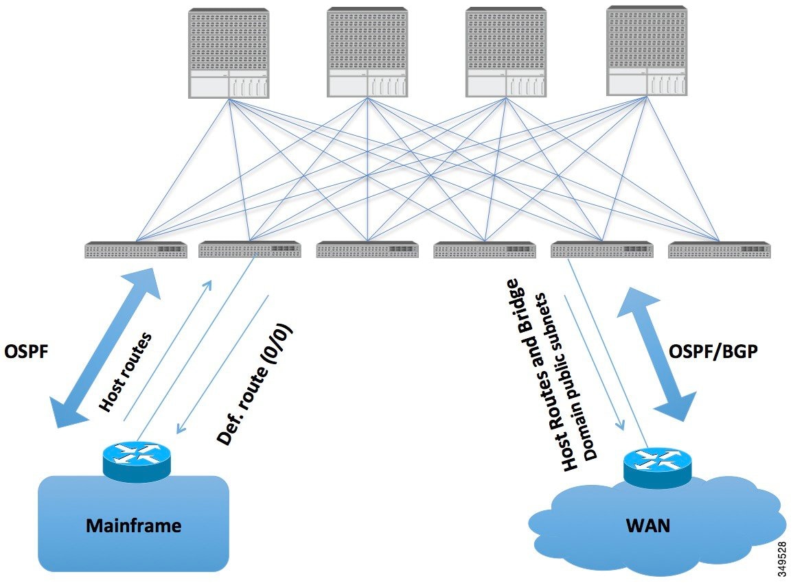
Mainframes that require the ACI fabric to be a transit domain for external connectivity through a WAN router and for east-west traffic within the fabric push host routes to the fabric that are redistributed within the fabric and towards external interfaces.
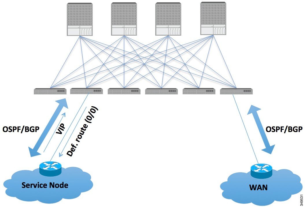
The VIP is the external facing IP address for a particular site or service. A VIP is tied to one or more servers or nodes behind a service node.
In such scenarios, the policies are administered at the demarcation points and ACI policies need not be imposed.
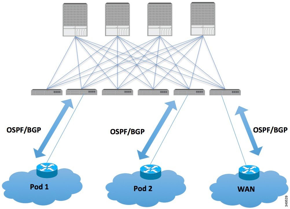
L4-L7 route peering is a special use case of the fabric as a transit where the ACI fabric serves as a transit OSPF/BGP domain for other PODs. Route Peering is used to configure OSPF/BGP peering on the L4-L7 service device so that it can exchange routes with the ACI leaf node to which it is connected. A common use case for route peering is Route Health Injection where the SLB VIP is advertised over OSPF/iBGP to clients outside the ACI fabric. See Appendix H for a configuration walk-through of this scenario.
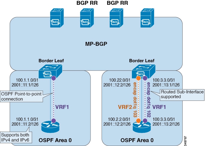
Transit Routing Overview
This article provides an overview of Layer 3 transit routing with the Cisco APIC.
The ACI software supports external Layer 3 connectivity with OSPF (NSSA) and iBGP. The ACI fabric advertises the tenant bridge domain subnets out to the external routers on the External Layer 3 Outside connections. The routes that are learned from the external routers are not advertised to the other external routers. The ACI fabric behaves like a stub network and it can be used to carry the traffic between the external Layer 3 domains.
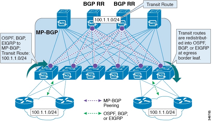
The ACI software adds support for transit routing. Multiple External Layer 3 Outside connections within a single tenant/context (VRF) are supported and the ACI fabric can advertise the routes that are learned from one External Layer 3 Outside connection to another External Layer 3 Outside connection. The external Layer 3 domains peer with the ACI fabric on the leaf switches (border leaves). The fabric is a transit Multiprotocol-Border Gateway Protocol (MP-BGP) domain between the peers.
The ACI fabric configuration for external Layer 3 Outside connections is done at the tenant/VRF level. The routes that are learned from the external peers are imported into MP-BGP at the ingress leaf per VRF. The prefixes that are learned from the External Layer 3 Outside connections are exported to the leaf switches only where the tenant VRF is present.
- Route Distribution Within the ACI Fabric
- External Layer 3 Outside Connection Types
- Supported Transit Combination Matrix
- OSPF Layer 3 Outside Connections
- EIGRP Layer 3 Outside Connections
- BGP Protocol Peering to External BGP Speakers
- Transit Route Control
- ACI Route Redistribution
- Controls Enabled for Subnets Configured under the Layer 3 Outside Network Instance Profile
- Advertising Tenant BD Subnets Outside the Fabric
- Tenant EPG to Layer 3 Outside Contract
- Advertising a Default Route
- Route Control Profile Policies
- Security Import Policies
Route Distribution Within the ACI Fabric
ACI supports the VRF-lite implementation when connecting to the external routers. Using sub-interfaces, the border leaf can provide Layer 3 outside connections for the multiple tenants with one physical interface. The VRF-lite implementation requires one protocol session per tenant.
Within the ACI fabric, Multiprotocol BGP (MP-BGP) is implemented between the leaf and the spine switches to propagate the external routes within the ACI fabric. The BGP route reflector technology is deployed in order to support a large number of leaf switches within a single fabric. All of the leaf and spine switches are in one single BGP Autonomous System (AS). Once the border leaf learns the external routes, it can then redistribute the external routes of a given VRF to an MP-BGP address family VPN version 4 or VPN version 6. With address family VPN version 4, MP-BGP maintains a separate BGP routing table for each VRF. Within MP-BGP, the border leaf advertises routes to a spine switch, that is a BGP route reflector. The routes are then propagated to all the leaves where the VRFs (or private network in the APIC GUI’s terminology) are instantiated.
External Layer 3 Outside Connection Types
ACI supports the following External Layer 3 Outside connection options:
-
Static Routing (supported for IPv4 and IPv6)
-
OSPFv2 for normal and NSSA areas (IPv4)
-
OSPFv3 for normal and NSSA areas (IPv6)
-
iBGP (IPv4 and IPv6)
-
eBGP (IPv4 and IPv6)
-
EIGRP (IPv4 only)
The External Layer 3 Outside connections are supported on the following interfaces:
-
Layer 3 Routed Interface
-
Sub-interface with 802.1Q tagging - With sub-interface, the same physical interface can be used to provide a Layer 2 outside connection for multiple private networks.
-
Switched Virtual Interface (SVI) - With an SVI interface, the same physical interface that supports Layer 2 and Layer 3 and the same physical interface can be used for a Layer 2 outside connection and a Layer 3 outside connection.
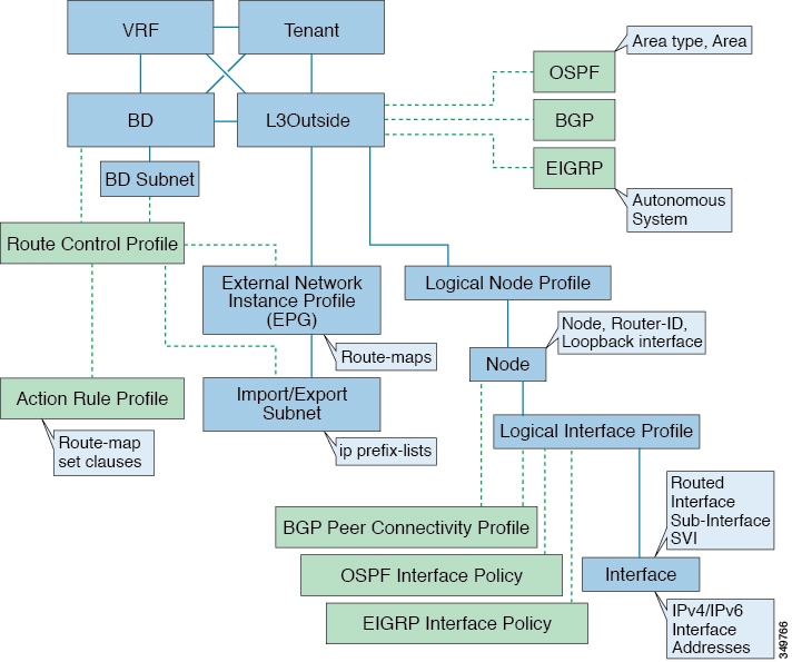
The managed objects that are used for the L3Outside connections are:
-
External Layer 3 Outside (L3ext): Routing protocol options (OSPF area type, area, EIGRP AS, BGP), private network, External Physical domain.
-
Logical Node Profile: Profile where one or more nodes are defined for the External Layer 3 Outside connections. The router-IDs and the loopback interface configuration is defined in the profile.
Note
Use same router-ID for the same node across multiple External Layer 3 Outside connections.
-
Logical Interface Profile: IP interface configuration for IPv4 and IPv6 interfaces. It is supported on the Route Interfaces, Routed Sub-Interfaces, and SVIs. The SVIs can be configured on physical ports, port-channels or VPCs.
-
OSPF Interface Policy: OSPF Network Type, priority etc.
-
EIGRP Interface Policy: Timers, split horizon setting etc
-
BGP Peer Connectivity Profile: The profile where most BGP peer settings, remote-as, local-as, and BGP peer connection options are configured. The BGP peer connectivity profile can be associated with the logical interface profile or the loopback interface under the node profile. This determines the update-source configuration for the BGP peering session.
-
External Network Instance Profile (EPG) (l3extInstP): The external EPG is also referred to as the prefix based EPG or InstP. The import and export route control policies, security import polices, and contract associations are defined in this profile. Multiple external EPGs can be configured under a single L3Out. Multiple external EPGs may be used when a different route or a security policy is defined on a single External Layer 3 Outside connections. An external EPG or multiple external EPGs combine into a route-map. The import/export subnets defined under the external EPG associate to the IP prefix-list match clauses in the route-map. The external EPG is also where the import security subnets and contracts are associated. This is used to permit or drop traffic for this L3out.
-
Action Rules Profile: The action rules profile is used to define the route-map set clauses for the L3Out. The supported set clauses are the BGP communities (standard and extended), Tags, Preference, Metric, and Metric type.
-
Route Control Profile: The route-control profile is used to reference the action rules profile(s). This can be an ordered list of action rules profiles. The Route Control Profile can be referenced by a tenant BD, BD subnet, external EPG, or external EPG subnet.
There are additional protocol settings for BGP, OSPF, and EIGRP L3Outs. These settings are configured per tenant in the ACI Protocol Policies section in the GUI.
Supported Transit Combination Matrix
|
Layer 3 Outside Connection Type |
OSPF |
iBGP | eBGP |
EIGRP |
Static Route |
||||
|---|---|---|---|---|---|---|---|---|---|
|
iBGP over OSPF |
iBGP over Static route |
iBGP over direct connection |
eBGP over OSPF |
eBGP over direct connection |
|||||
|
OSPF |
Yes |
Yes* |
Yes |
X |
Yes |
Yes |
Yes |
Yes |
|
| iBGP |
iBGP over OSPF |
Yes* |
X |
X |
X |
X |
Yes |
X |
Yes |
|
iBGP over Static route |
Yes |
X |
X |
X |
X |
Yes |
X |
Yes |
|
|
iBGP over direct connection |
Yes |
X |
X |
X |
X |
Yes |
X |
Yes |
|
| eBGP |
eBGP over OSPF |
Yes |
X |
X |
Yes |
Yes |
X |
X |
X |
|
eBGP over direct connection |
Yes |
Yes |
X |
Yes |
X |
Yes |
X |
Yes |
|
|
EIGRP |
Yes |
X |
X |
X |
X |
X |
X |
||
|
Static route |
Yes |
Yes |
Yes |
Yes |
X |
Yes |
Yes |
||
-
* = Not supported on the same leaf switch
-
X = Unsupported/Untested combinations
-
bold text = Supported in this release
OSPF Layer 3 Outside Connections
OSPF Layer 3 Outside connections can be normal or NSSA areas. The backbone (area 0) area is also supported as an OSPF Layer 3 Outside connection area. ACI supports both OSPFv2 for IPv4 and OSPFv3 for IPv6. When creating an OSPF Layer 3 Outside, it is not necessary to configure the OSPF version. The correct OSPF process is created automatically based on the interface profile configuration (IPv4 or IPv6 addressing). Both IPv4 and IPv6 protocols are supported on the same interface (dual stack) but it is necessary to create two separate interface profiles.
Layer 3 Outside connections are supported for the routed interfaces, routed sub-interfaces, and SVIs. The SVIs are used when there is a need to share the physical connect for both L2 and L3 traffic. The SVIs are supported on ports, port-channels, and VPC port-channels.
When an SVI is used for an Layer 3 Outside connection, an external bridge domain is created on the border leaf switches. The external bridge domain allows connectivity between the two VPC switches across the ACI fabric. This allows both the VPC switches to establish the OSPF adjacencies with each other and the external OSPF device.
When running OSPF over a broadcast network, the time to detect a failed neighbor is the dead time interval (default 40 seconds). Reestablishing the neighbor adjacencies after a failure may also take longer due to designated router (DR) election.
Note | A link or port-channel failure to one VPC Node does not cause an OSPF adjacency to go down. The OSPF adjacency can stay up via the external BD accessible through the other VPC node. |
EIGRP Layer 3 Outside Connections
EIGRP Layer 3 Outside connections are supported on the same interface types as OSPF except that IPv6 is not supported for EIGRP.
Note | VPC/SVI configuration for EIGRP is the same as OSPF. |
BGP Protocol Peering to External BGP Speakers
ACI supports peering between the border leaves and the external BGP speakers using iBGP and eBGP. ACI supports the following connections for BGP peering:
-
iBGP peering over OSPF
-
eBGP peering over OSPF
-
iBGP peering over direct connection
-
eBGP peering over direct connection
-
iBGP peering over static route
Note | When OSPF is used with BGP peering, OSPF is only used to learn and advertise the routes to the BGP peering addresses. All route control applied to the Layer 3 Outside Network (EPG) are applied at the BGP protocol level. |
ACI supports a number of features for iBGP and eBGP connectivity to external peers. The BGP features are configured on the BGP Peer Connectivity Profile.
The BGP peer connectivity profile features are described in the following table:
|
BGP Features |
Feature Description |
NX-OS Equivalent Commands |
|---|---|---|
|
Allow Self-AS |
Works with Allowed AS Number Count setting. |
allowas-in |
|
Disable peer AS check |
Disable checking of the peer AS number when advertising. |
disable-peer-as-check |
|
Next-hop self |
Always set the next hop attribute to the local peering address. |
next-hop-self |
|
Send community |
Send the community attribute to the neighbor. |
send-community |
|
Send community extended |
Send the extended community attribute to the neighbor. |
send-community extended |
|
Password |
The BGP MD5 authentication. |
password |
|
Allowed AS Number Count |
Works with Allow Self-AS feature. |
allowas-in |
|
Disable connected check |
Disable connected check for the directly connected EBGP neighbors (allowing EBGP neighbor peering from the loopbacks). |
|
|
TTL |
Set the TTL value for EBGP multihop connections. It is only valid for EBGP. |
ebgp-multihop <TTL> |
|
Autonomous System Number |
Remote Autonomous System number of the peer. |
neighbor <x.x.x.x> remote-as |
|
Local Autonomous System Number Configuration |
Options when using the Local AS feature. (No Prepend+replace-AS+dual-AS etc). |
|
|
Local Autonomous System Number |
The local AS feature used to advertise a different AS number than the AS assigned to the fabric MP-BGP Route Reflector Profile. It is only supported for the EBGP neighbors and the local AS number must be different than the route reflector policy AS. |
local-as xxx <no-prepend> <replace-as> <dual-as> |
Transit Route Control
An ACI fabric can have multiple external Layer 3 connections per tenant/VRF running dynamic routing protocols (OSPF, EIGRP, and BGP). Route control policies are implemented in the ACI fabric to control the distribution of the routes that are learned from an External Layer 3 Outside connection or configured as a static route. ACI supports import and export route control. Import and export route control uses the route-maps and the IP prefix-lists to control the import and export of the prefixes that are allowed into and advertised out of the ACI fabric.
The default setting for import route control is to allow all the prefixes. All leaf switches in the ACI fabric learn of all the external prefixes where that VRF is deployed. The default setting for the export route control is to deny all the prefixes. The import route control can be enabled but is only supported for BGP. All OSPF and EIGRP learned routes are allowed into their respective protocol on the border leaf where the Layer 3 Outside connection is deployed. These prefixes are redistributed (imported) into MP-BGP at the ingress border leaf per tenant/VRF.
Import Route Control
-
Controls the import of prefixes into the routing table on the ingress leaf.
-
Disabled by default.
-
Only supported for BGP.
-
Implemented with an input route-map associated to the external BGP neighbor.
Export Route Control
-
Controls the export of transit prefixes advertised out of the ACI fabric (over Layer 3 Outside connections).
-
Supported for all Layer 3 Outside connection types.
-
Always enabled.
-
Default setting is to deny all the prefixes.
-
Implemented with redistribution route-map (OSPF/EIGRP) and neighbor route-map (BGP).
-
Not used to control the export of the tenant subnets or the originating default route.
Import and export route control is configured under the External Network Instance Profile (l3extInstP).
Note | The import/export route control is used to control the import and export of the transit route prefixes (the routes that are learned from the external Layer 3 devices) and the static routes. The import/export route control is not used for the tenant subnets (the subnets that are configured under the tenant bridge domains) or when originating a default route. |
ACI Route Redistribution
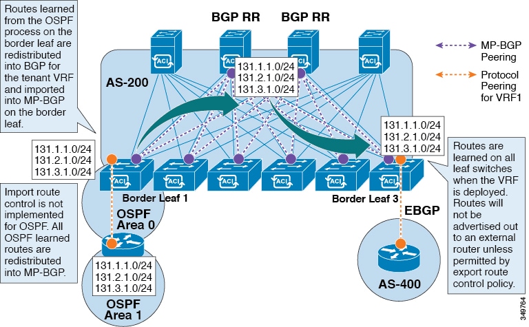
-
The routes that are learned from the OSPF process on the border leaf are redistributed into BGP for the tenant VRF and they are imported into MP-BGP on the border leaf.
-
The import route control is not implemented for OSPF. All OSPF learned routes are redistributed into MP-BGP.
-
The routes are learned on the border leaf where the VRF is deployed. The routes are not advertised to the External Layer 3 Outside connection unless it is permitted by the export route control.
Note | When a subnet for a bridge domain/EPG is set to Advertise Externally, the subnet is programmed as a static route on a border leaf. When the static route is advertised, it is redistributed into the EPG's Layer 3 outside network routing protocol as an external network, not injected directly into the routing protocol. |
Controls Enabled for Subnets Configured under the Layer 3 Outside Network Instance Profile
|
Route control Setting |
Use |
Options |
|---|---|---|
|
Export Route Control |
To allow the prefixes that are advertised to the external peers. Implemented with IP prefix-lists. |
Specific match (prefix and prefix length). |
|
Import Route Control |
To allow prefixes that are inbound from the external BGP peers. Implemented with IP prefix-lists. |
Specific match (prefix and prefix length) . |
|
Security Import Subnet |
To permit the packets between two prefix based EPGs. Implemented with ACLs. |
Uses the ACL match prefix/wildcard match rules. |
|
Aggregate Export |
To allow all prefixes to be advertised to the external peers. Implemented with 0.0.0.0/ le 32 IP prefix-list. |
Only supported for 0.0.0.0/0 subnet (all prefixes). |
|
Aggregate Import |
To allow all prefixes that are inbound from an external BGP peer. Implemented with 0.0.0.0/0 le 32 IP prefix-list. |
Only supported for 0.0.0.0/0 subnet (all prefixes). |
Advertising Tenant BD Subnets Outside the Fabric
The import and export route control policies only apply to the transit routes (the routes that are learned from other external peers) and the static routes. The subnets internal to the fabric that are configured on the tenant BD subnets are not advertised out using the export policy subnets. The tenant subnets are still permitted using the IP prefix-lists and the route-maps but they are implemented using different configuration steps. See the following configuration steps to advertise the tenant subnets outside the fabric:
| Step 1 | Configure the tenant subnet scope as Public Subnet in the subnet properties window. |
| Step 2 | (Optional) Set the Subnet Control as ND RA Prefix in the subnet properties window. |
| Step 3 | Associate the tenant bridge domain (BD) with external Layer 3 Outside. |
| Step 4 | Create contract
(provider/consumer) association between the tenant EPG and the external EPG.
Setting the BD subnet to scope Public and associating the BD to the Layer 3 Outside creates an IP prefix-list and the route-map sequence entry on the border leaf for the BD subnet prefix. |
Tenant EPG to Layer 3 Outside Contract
The tenant EPG needs a contract provider/consumer association with the Layer 3 Outside connection. It creates a route entry for the subnet on the border leaf (If the tenant BD is not previously deployed on the leaf) and it is also used to permit the traffic in the data plane.
-
The tenant EPG/BD is already deployed on the border leaf.
-
OR the tenant EPG/BD has a contract with a tenant/EPG deployed on the border leaf.
Note | This entry is valid only if the tenant private network (context) is set with Policy Control Enforcement set to enforced. If Policy Control Enforcement is set to unenforced, the tenant prefixes are present on the border leaf without any contracts. |
Advertising a Default Route
For external connections to the fabric that only require a default route, there is support for originating a default route for OSPF, EIGRP, and BGP Layer 3 Outside connections. If a default route is received from an external peer, this route can be redistributed out to another peer following the transit export route control as described earlier in this article.
A default route can also be advertised out using a Default Route Leak Policy. This policy supports advertising a default route if it is present in the routing table or it supports advertising a default route always. The Default Route Leak Policy is configured at the Layer 3 Outside connection.
When creating a Default Route Leak Policy, follow these guidelines:
-
For BGP, the Always property is not applicable.
-
For BGP, when choosing the Scope property, you must choose Outside.
-
For OSPF, the Scope value Context creates a type-5 LSA while the Scope value Outside creates type-7 LSA. This selection depends on the area type being used in that Layer3 outside. Therefore, if the area type is regular, set the scope to Context and if the area type is NSSA, set the scope to Outside.
Route Control Profile Policies
The ACI fabric also supports the route-map set clauses for the routes that are advertised into and out of the fabric. The route-map set rules are configured with the Route Control Profile policies and the Action Rule Profiles.
ACI supports the following set options:
|
Property |
OSPF |
EIGRP |
BGP |
Comments |
|---|---|---|---|---|
|
Set Community |
|
|
Yes |
Supports regular and extended communities. |
|
Route Tag |
Yes |
Yes |
|
Supported only for BD subnets. Transit prefixes are always assigned the tag 4294967295. |
|
Preference |
|
|
Yes |
Sets BGP local preference. |
|
Metric |
Yes |
|
Yes |
Sets MED for BGP. Will change the metric for EIGRP but you cannot specify the EIGRP composite metric. |
|
Metric Type |
Yes |
|
|
OSPF Type-1 and OSPF Type-2. |
The Route Profile Polices are created under the Layer 3 Outside connection. A Route Control Policy can be referenced by the following objects:
Here is an example of using Import Route Control for BGP and setting the local preference for an external route learned from two different Layer 3 Outsides. The Layer 3 Outside connection for the external connection to AS300 is configured with the Import Route Control enforcement. An action rule profile is configured to set the local preference to 200 in the Action Rule Profile for Local Preference window.
The Layer 3 Outside connection External EPG is configured with a 0.0.0.0/0 import aggregate policy to allow all the routes. This is necessary because the import route control is enforced but any prefixes should not be blocked. The import route control is enforced to allow setting the local preference. Another import subnet 151.0.1.0/24 is added with a Route Profile that references the Action Rule Profile in the External EPG settings for Route Control Profile window.
Use the show ip bgp vrf overlay-1 command to display the MP-BGP table. The MP-BGP table on the spine displays the prefix 151.0.1.0/24 with local preference 200 and a next hop of the border leaf for the BGP 300 Layer 3 Outside connection.
There are two special route control profiles—default-import and default-export. If the user configures using the names default-import and default-export, then the route control profile is automatically applied at the Layer3 outside level for both import and export. The default-import and default-export route control profiles cannot be configured using the 0.0.0.0/0 aggregate.
Note | When you configure Layer 3 Outside (L3Out) connections to external routers, it is critical that the MTU be set appropriately on both sides. On some platforms, such as ACI, Cisco NX-OS, and Cisco IOS, the configurable MTU value takes into account packet headers (resulting in a max packet size to be set as 9000 bytes), whereas other platforms such as IOS-XR configure the MTU value exclusive of packet headers (resulting in a max packet size of 8986 bytes). For the appropriate MTU values for each platform, see the relevant configuration guides. Cisco highly recommends you test the MTU using CLI-based commands. For example, on the Cisco NX-OS CLI, use a command such as ping 1.1.1.1 df-bit packet-size 9000 source-interface ethernet 1/1 |
Security Import Policies
The policies discussed in the documentation have dealt with the exchange of the routing information into and out of the ACI fabric and the methods that are used to control and tag the routes. The ACI fabric operates in a whitelist model where the default behavior is to drop all the data plane traffic between the endpoint groups unless explicitly permitted by the policy. This whitelist model applies to the external EPGs and the tenant EPGs.
There are some differences in how the security policies are configured and how they are implemented for the transit traffic compared to the tenant traffic:
Transit Security Policies
-
Uses prefix filtering.
-
Does not support Ethertype, protocol, L4 port, and TCP flag filters.
-
Implemented with the security import subnets (prefixes) and the contracts that are configured under the external EPG.
Tenant EPG Security Policies
-
Does not use prefix filtering.
-
Supports Ethertype, protocol, L4 port, and TCP flag filters.
-
Supported for tenant EPG←→EPG and tenant EPG←→External EPGs.
If there are no contracts between the external prefix based EPGs, the traffic is dropped. Allowing traffic between the two external EPGs requires configuring a contract and a security prefix. As only prefix filtering is supported, the default filter can be used.
External Layer 3 Outside Connection Contracts
The union of prefixes for Layer 3 Outside connections are programmed on all the leaf nodes where the Layer 3 Outside connections are deployed. When more than two Layer 3 Outside connections are deployed, the use of the catch all rule 0.0.0.0/0 can allow traffic between the Layer 3 Outside connections that do not have a contract.
Configuring the Provider/Consumer contract associations and the security import subnets is done at the External Layer 3 Outside connection Instance Profile (instP).
When security import subnets are configured and the catch all rule 0.0.0.0/0 is supported, the security import subnets follow the ACL type rules. The security import subnet rule 10.0.0.0/8 matches all the addresses from 10.0.0.0 – 10.255.255.255. It is not required to configure an exact prefix match for the prefixes that are permitted by the route control subnets.
Care should be taken when configuring the security import subnets if more than two Layer 3 Outside connections are configured in the same VRF, due to the union of the rules.
Common Pervasive Gateway
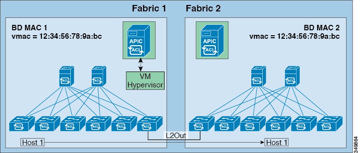
The per-bridge domain common pervasive gateway configuration requirements are as follows:
-
The bridge domain MAC (mac) values for each fabric must be unique.
Note
The default bridge domain MAC (mac) address values are the same for all ACI fabrics. The common pervasive gateway requires an administrator to configure the bridge domain MAC (mac) values to be unique for each ACI fabric.
-
The bridge domain virtual MAC (vmac) address and the subnet virtual IP address must be the same across all ACI fabrics for that bridge domain. Multiple bridge domains can be configured to communicate across connected ACI fabrics. The virtual MAC address and the virtual IP address can be shared across bridge domains.
- Configuring Common Pervasive Gateway Using the GUI
- Configuring Common Pervasive Gateway Using the REST API
- Configuring Common Pervasive Gateway Using the NX-OS Style CLI
Configuring Common Pervasive Gateway Using the GUI
-
The tenant, and VRF are created.
-
The bridge domain virtual MAC address and the subnet virtual IP address must be the same across all ACI fabrics for that bridge domain. Multiple bridge domains can be configured to communicate across connected ACI fabrics. The virtual MAC address and the virtual IP address can be shared across bridge domains.
-
The Bridge domain that is configured to communicate across ACI fabrics must be in flood mode
-
Only one EPG from a bridge domain (If the BD has multiple EPGs) should be configured on a border Leaf on the port which is connected to the second Fabric.
-
Do not connect hosts directly to an inter-connected Layer 2 network that enables a pervasive common gateway among the two ACI fabrics.
| Step 1 | On the menu bar, click TENANTS. |
| Step 2 | In the Navigation pane, expand the . |
| Step 3 | Right-click Bridge Domains, and click Create Bridge Domain. |
| Step 4 | In the
Create
Bridge Domain dialog box, perform the following actions and select
the appropriate attributes:
|
| Step 5 | Double click on
the
Bridge
Domain that you just created in the
Work pane, and perform the following actions:
|
| Step 6 | Create a L2out EPG to extend the BD to other Fabric by right
clicking on
External Bridged Networks and open the
Create Bridged Outside dialog box, and perform
the following actions:
|
Configuring Common Pervasive Gateway Using the REST API
Example: <!-Things that are bolded only matters-->
<?xml version="1.0" encoding="UTF-8"?>
<!-- api/policymgr/mo/.xml -->
<polUni>
<fvTenant name="test">
<fvCtx name="test"/>
<fvBD name="test" vmac="12:34:56:78:9a:bc">
<fvRsCtx tnFvCtxName="test"/>
<!-- Primary address -->
<fvSubnet ip="192.168.15.254/24" preferred="yes"/>
<!-- Virtual address -->
<fvSubnet ip="192.168.15.1/24" virtual="yes"/>
</fvBD>
<fvAp name="test">
<fvAEPg name="web">
<fvRsBd tnFvBDName="test"/>
<fvRsPathAtt tDn="topology/pod-1/paths-101/pathep-[eth1/3]" encap="vlan-1002"/>
</fvAEPg>
</fvAp>
</fvTenant>
</polUni>
|
Configuring Common Pervasive Gateway Using the NX-OS Style CLI
Example: apic1#configure apic1(config)#tenant demo apic1(config-tenant)#bridge-domain test apic1(config-tenant-bd)#l2-unknown-unicast flood apic1(config-tenant-bd)#arp flooding apic1(config-tenant-bd)#exit apic1(config-tenant)#interface bridge-domain test apic1(config-tenant-interface)#multi-site-mac-address 12:34:56:78:9a:bc apic1(config-tenant-interface)#mac-address 00:CC:CC:CC:C1:01 (Should be unique for each ACI fabric) apic1(config-tenant-interface)#ip address 192.168.10.1/24 multi-site apic1(config-tenant-interface)#ip address 192.168.10.254/24 (Should be unique for each ACI fabric) |
 Feedback