Cisco APIC Basic Configuration Guide, Release 1.x
Bias-Free Language
The documentation set for this product strives to use bias-free language. For the purposes of this documentation set, bias-free is defined as language that does not imply discrimination based on age, disability, gender, racial identity, ethnic identity, sexual orientation, socioeconomic status, and intersectionality. Exceptions may be present in the documentation due to language that is hardcoded in the user interfaces of the product software, language used based on RFP documentation, or language that is used by a referenced third-party product. Learn more about how Cisco is using Inclusive Language.
- Updated:
- December 4, 2015
Chapter: ACI Fabric Access Layer 2 Connectivity
- Layer 2 Workflows
- Networking Domains
- Attachable Entity Profile
- Configuration of Leaf Switch Physical Ports
- Configuration of Leaf Switch Port Channels
- Configuration of Leaf Switch Virtual Port Channels
- Basic FEX Configuration
- FEX Port Channel Configuration
- FEX Virtual Port Channel Configuration
- About Traffic Storm Control
- Intra-EPG Endpoint Isolation
ACI Fabric Access
Layer 2 Connectivity
This chapter contains the following sections:
- Layer 2 Workflows
- Networking Domains
- Attachable Entity Profile
- Configuration of Leaf Switch Physical Ports
- Configuration of Leaf Switch Port Channels
- Configuration of Leaf Switch Virtual Port Channels
- Basic FEX Configuration
- FEX Port Channel Configuration
- FEX Virtual Port Channel Configuration
- About Traffic Storm Control
- Intra-EPG Endpoint Isolation
Layer 2 Workflows
ACI Virtual Port Channel Workflow
This workflow provides an overview of the steps required to configure a virtual port channel (VPC).
1. Prerequisites
2. Configure the Virtual Port Channel
-
On the APIC menu bar, navigate to Fabric > Access Policies > Quick Start, and click Configure an interface, PC, and VPC to open the quick start wizard.
-
Provide the specifications for: the policy name, switch IDs and interfaces the virtual port channel will use; the Interface Policy group port speed, storm control, CDP, LLDP etc.; the Attached Device Type as an External Bridged Device, and specify the VLAN and domain that will be used.
-
Use the CLI show int command on the ACI leaf switches where the external switch is attached to verify that the switches and virtual port channel are configured accordingly.
Note: While this configuration enables hardware connectivity, no data traffic can flow without a valid application profile, EPG, and contract that is associated with this hardware configuration.
Configure the Application Profile
-
On the APIC menu bar, navigate to Tenant > <tenant name> > Quick Start, and click Create an application profile under the tenant quick start wizard.
-
Configure the endpoint groups (EPGs), contracts, bridge domain, subnet, and context.
-
Associate the application profile EPGs with the virtual port channel switch profile created above.
Suggested topics
For additional information, see the following topics:
Networking Domains
A fabric administrator creates domain policies that configure ports, protocols, VLAN pools, and encapsulation. These policies can be used exclusively by a single tenant, or shared. Once a fabric administrator configures domains in the ACI fabric, tenant administrators can associate tenant endpoint groups (EPGs) to domains.
These networking domain profiles can be configured:
-
VMM domain profiles (vmmDomP) are required for virtual machine hypervisor integration.
-
Physical domain profiles (physDomP) are typically used for bare metal server attachment and management access.
-
Bridged outside network domain profiles (l2extDomP) are typically used to connect a bridged external network trunk switch to a leaf switch in the ACI fabric.
-
Routed outside network domain profiles (l3extDomP) are used to connect a router to a leaf switch in the ACI fabric.
A domain is configured to be associated with a VLAN pool. EPGs are then configured to use the VLANs associated with a domain.
 Note | EPG port and VLAN configurations must match those specified in the domain infrastructure configuration with which the EPG associates. If not, the APIC will raise a fault. When such a fault occurs, verify that the domain infrastructure configuration matches the EPG port and VLAN configurations. |
Attachable Entity Profile
The ACI fabric provides multiple attachment points that connect through leaf ports to various external entities such as bare metal servers, virtual machine hypervisors, Layer 2 switches (for example, the Cisco UCS fabric interconnect), or Layer 3 routers (for example Cisco Nexus 7000 Series switches). These attachment points can be physical ports, FEX ports, port channels, or a virtual port channel (vPC) on leaf switches.
An Attachable Entity Profile (AEP) represents a group of external entities with similar infrastructure policy requirements. The infrastructure policies consist of physical interface policies that configure various protocol options, such as Cisco Discovery Protocol (CDP), Link Layer Discovery Protocol (LLDP), Maximum Transmission Unit (MTU), or Link Aggregation Control Protocol (LACP).
An AEP is required to deploy VLAN pools on leaf switches. Encapsulation blocks (and associated VLANs) are reusable across leaf switches. An AEP implicitly provides the scope of the VLAN pool to the physical infrastructure.
The following AEP requirements and dependencies must be accounted for in various configuration scenarios, including network connectivity and VMM domains:
-
The AEP defines the range of allowed VLANS but it does not provision them. No traffic flows unless an EPG is deployed on the port. Without defining a VLAN pool in an AEP, a VLAN is not enabled on the leaf port even if an EPG is provisioned.
-
A particular VLAN is provisioned or enabled on the leaf port that is based on EPG events either statically binding on a leaf port or based on VM events from external controllers such as VMware vCenter or Microsoft Azure Service Center Virtual Machine Manager (SCVMM).
A virtual machine manager (VMM) domain automatically derives physical interface policies from the interface policy groups of an AEP.
An override policy at the AEP can be used to specify a different physical interface policy for a VMM domain. This policy is useful in scenarios where a VM controller is connected to the leaf switch through an intermediate Layer 2 node, and a different policy is desired at the leaf switch and VM controller physical ports. For example, you can configure LACP between a leaf switch and a Layer 2 node. At the same time, you can disable LACP between the VM controller and the Layer 2 switch by disabling LACP under the AEP override policy.
Configuration of Leaf Switch Physical Ports
- Configuring Leaf Switch Physical Ports Using the Advanced GUI
- Configuring Physical Ports in Leaf Nodes Using the NX-OS CLI
Configuring Leaf Switch Physical Ports Using the Advanced GUI
The procedure below uses a Quick Start wizard.
-
The ACI fabric is installed, APIC controllers are online, and the APIC cluster is formed and healthy.
-
An APIC fabric administrator account is available that will enable creating the necessary fabric infrastructure configurations.
-
The target leaf switches are registered in the ACI fabric and available.
What to Do Next
While this
configuration enables hardware connectivity, no data traffic can flow without a
valid application profile, EPG, and contract that is associated with this
hardware configuration.
Note
Configuring Physical Ports in Leaf Nodes Using the NX-OS CLI
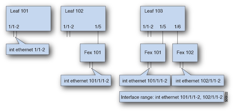
The commands in the following examples create many managed objects (MOs) in the ACI policy model that are fully compatible with the REST API/SDK and GUI. However, the CLI user can focus on the intended network configuration instead of ACI model internals.
The following figure shows examples of Ethernet ports directly on leaf nodes or FEX modules attached to leaf nodes and how each is represented in the CLI. For FEX ports, the fex-id is included in the naming of the port itself as in ethernet 101/1/1. While describing an interface range, the ethernet keyword need not be repeated as in NX-OS. Example: interface ethernet 101/1/1-2, 102/1/1-2.
| Command or Action | Purpose | |||
|---|---|---|---|---|
| Step 1 | configure
Example: apic1# configure |
Enters global configuration mode. | ||
| Step 2 | leaf
node-id
Example: apic1(config)# leaf 102 |
Specifies the leaf or leafs to be configured. The node-id can be a single node ID or a range of IDs, in the form node-id1-node-id2, to which the configuration will be applied. | ||
| Step 3 | interface
type
Example: apic1(config-leaf)# interface ethernet 1/2 |
Specifies the interface that you are configuring. You can specify the interface type and identity. For an Ethernet port, use “ethernet slot / port.” | ||
| Step 4 | fex associate
node-id
Example: apic1(config-leaf-if)# fex associate 101 | (Optional) If the
interface or interfaces to be configured are FEX interfaces, you must use this
command to attach the FEX module to a leaf node before configuration.
| ||
| Step 5 | speed
speed
Example: apic1(config-leaf-if)# speed 10G |
The speed setting is shown as an example. At this point you can configure any of the interface settings shown in the table below. |
The following table shows the interface settings that can be configured at this point.
|
Command |
Purpose |
|---|---|
|
[no] shut |
Shut down physical interface |
|
[no] speed speedValue |
Set the speed for physical interface |
|
[no] link debounce time time |
Set link debounce |
|
[no] negotiate auto |
Configure negotiate |
|
[no] cdp enable |
Disable/enable Cisco Discovery Protocol (CDP) |
|
[no] mcp enable |
Disable/enable Mis-cabling Protocol (MCP) |
|
[no] lldp transmit |
Set the transmit for physical interface |
|
[no] lldp receive |
Set the LLDP receive for physical interface |
|
spanning-tree {bpduguard | bpdufilter} {enable | disable} |
Configure spanning tree BPDU |
|
[no] storm-control level percentage [ burst-rate percentage ] |
Storm-control configuration (percentage) |
|
[no] storm-control pps packets-per-second burst-rate packets-per-second |
Storm-control configuration (packets-per-second) |
Examples
Configure one port in a leaf node. The following example shows how to configure the interface eth1/2 in leaf 101 for the following properties: speed, cdp, and admin state.
apic1# configure
apic1(config)# leaf 101
apic1(config-leaf)# interface ethernet 1/2
apic1(config-leaf-if)# speed 10G
apic1(config-leaf-if)# cdp enable
apic1(config-leaf-if)# no shut
Configure multiple ports in multiple leaf nodes. The following example shows the configuration of speed for interfaces eth1/1-10 for each of the leaf nodes 101-103.
apic1(config)# leaf 101-103
apic1(config-leaf)# interface eth 1/1-10
apic1(config-leaf-if)# speed 10G
Attach a FEX to a leaf node. The following example shows how to attach a FEX module to a leaf node. Unlike in NX-OS, the leaf port Eth1/5 is implicitly configured as fabric port and a FEX fabric port-channel is created internally with the FEX uplink port(s). In ACI, the FEX fabric port-channels use default configuration and no user configuration is allowed.
Note | This step is required before creating a port-channel using FEX ports, as described in the next example. |
apic1(config)# leaf 102
apic1(config-leaf)# interface eth 1/5
apic1(config-leaf-if)# fex associate 101
Configure FEX ports attached to leaf nodes. This example shows configuration of speed for interfaces eth1/1-10 in FEX module 101 attached to each of the leaf nodes 102-103. The FEX ID 101 is included in the port identifier. FEX IDs start with 101 and are local to a leaf.
apic1(config)# leaf 102-103
apic1(config-leaf)# interface eth 101/1/1-10
apic1(config-leaf-if)# speed 1G
Configuration of Leaf Switch Port Channels
- ACI Leaf Switch Port Channel Configuration Using the Advanced GUI
- Configuring Port Channels in Leaf Nodes Using the NX-OS CLI
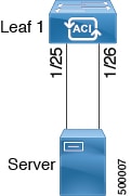
ACI Leaf Switch Port Channel Configuration Using the Advanced GUI
The procedure below uses a Quick Start wizard.
Note | This procedure provides the steps for attaching a server to an ACI leaf switch interface. The steps would be the same for attaching other kinds of devices to an ACI leaf switch interface. 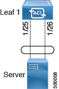 |
-
The ACI fabric is installed, APIC controllers are online, and the APIC cluster is formed and healthy.
-
An APIC fabric administrator account is available that will enable creating the necessary fabric infrastructure configurations.
-
The target leaf switches are registered in the ACI fabric and available.
| Step 1 | On the APIC menu bar, navigate to , and click Configure an interface, PC, and VPC. | ||
| Step 2 | In the Select Switches To Configure Interfaces work area, click the large + to select switches to configure. In the Switches section, click the + to add switch ID(s) from the drop-down list of available switch IDs and click Update. | ||
| Step 3 | Click the
large
+ to configure switch interfaces.
The interface policy group is a named policy that specifies the group of interface policies you will apply to the selected interfaces of the switch. Examples of interface policies include Link Level Policy (for example, 1gbit port speed), Storm Control Interface Policy, and so forth.
Verification: Use the CLI show int command on the switch where the server is attached to verify that the switch interface is configured accordingly. |
What to Do Next
While this
configuration enables hardware connectivity, no data traffic can flow without a
valid application profile, EPG, and contract that is associated with this
hardware configuration.
Note
Configuring Port Channels in Leaf Nodes Using the NX-OS CLI
Port-channels are logical interfaces in NX-OS used to aggregate bandwidth for multiple physical ports and also for providing redundancy in case of link failures. In NX-OS, port-channel interfaces are identified by user-specified numbers in the range 1 to 4096 unique within a node. Port-channel interfaces are either configured explicitly (using interface port-channel command) or created implicitly (using channel-group command). The configuration of the port-channel interface is applied to all the member ports of the port-channel. There are certain compatibility parameters (speed, for example) that cannot be configured on the member ports.
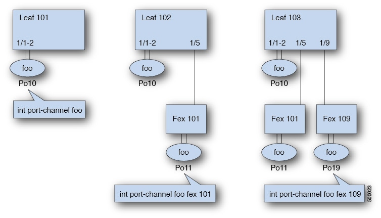
In the ACI model, port-channels are configured as logical entities identified by a name to represent a collection of policies that can be assigned to set of ports in one or more leaf nodes. Such assignment creates one port-channel interface in each of the leaf nodes identified by an auto-generated number in the range 1 to 4096 within the leaf node, which may be same or different among the nodes for the same port-channel name. The membership of these port-channels may be same or different as well. When port-channel is created on the FEX ports, the same port-channel name can be used to create one port-channel interface in each of the FEX attached to the leaf node. Thus, it is possible to create up to N+1 unique port-channel interfaces (identified by the auto-generated port-channel numbers) for each leaf node attached to N FEX modules. This is illustrated with the examples below. Port-channels on the FEX ports are identified by specifying the fex-id along with the port-channel name (interface port-channel foo fex 101, for example).
| Command or Action | Purpose | |||
|---|---|---|---|---|
| Step 1 | configure
Example: apic1# configure |
Enters global configuration mode. | ||
| Step 2 | template
port-channel
channel-name
Example: apic1(config)# template port-channel foo |
Creates a new port-channel or configures an existing port-channel (global configuration). | ||
| Step 3 | channel-mode
active
Example: apic1(config-if)# channel-mode active |
| ||
| Step 4 |
exit
Example: apic1(config-if)# exit |
Returns to configure mode. | ||
| Step 5 | leaf
node-id
Example: apic1(config)# leaf 101 |
Specifies the leaf or leafs to be configured. The node-id can be a single node ID or a range of IDs, in the form node-id1-node-id2, to which the configuration will be applied. | ||
| Step 6 | interface
type
Example: apic1(config-leaf)# interface ethernet 1/1-2 |
Specifies the interface or range of interfaces that you are configuring to the port-channel. | ||
| Step 7 |
[no]
channel-group
channel-name
Example: apic1(config-leaf-if)# channel-group foo |
Assigns the interface or range of interfaces to the port-channel. Use the keyword no to remove the interface from the port-channel. To change the port-channel assignment on an interface, you can enter the channel-group command without first removing the interface from the previous port-channel. | ||
| Step 8 | lacp
port-priority
priority
Example: apic1(config-leaf-if)# lacp port-priority 1000 apic1(config-leaf-if)# lacp rate fast | (Optional)
This setting and other per-port LACP properties can be applied to member ports of a port-channel at this point.
|
The following table shows various commands for global configurations of port channel properties in the ACI model. These commands can also be used for configuring overrides for port channels in a specific leaf in the (config-leaf-if) CLI mode. The configuration made on the port-channel is applied to all member ports.
|
CLI Syntax |
Feature |
|---|---|
|
[no] speed <speedValue> |
Set the speed for port-channel |
|
[no] link debounce time <time> |
Set Link Debounce for port-channel |
|
[no] negotiate auto |
Configure Negotiate for port-channel |
|
[no] cdp enable |
Disable/Enable cdp for port-channel |
|
[no] mcp enable |
Disable/Enable mcp for port-channel |
|
[no] lldp transmit |
Set the transmit for port-channel |
|
[no] lldp receive |
Set the lldp receive for port-channel |
|
spanning-tree <bpduguard | bpdufilter> <enable | disable> |
Configure spanning tree bpdu |
|
[no] storm-control level <percentage> [ burst-rate <percentage> ] |
Storm-control configuration (percentage) |
|
[no] storm-control pps <packet-per-second> burst-rate <packets-per-second> |
Storm-control configuration (packets-per-second) |
|
[no] channel-mode { active | passive | on| mac-pinning } |
LACP mode for the link in port-channel l |
|
[no] lacp min-links <value> |
Set minimum number of links |
|
[no] lacp max-links <value> |
Set maximum number of links |
|
[no] lacp fast-select-hot-standby |
LACP fast select for hot standby ports |
|
[no] lacp graceful-convergence |
LACP graceful convergence |
|
[no] lacp load-defer |
LACP load defer member ports |
|
[no] lacp suspend-individual |
LACP individual Port suspension |
|
[no] lacp port-priority |
LACP port priority |
|
[no] lacp rate |
LACP rate |
Examples
Configure a port channel (global configuration). A logical entity foo is created that represents a collection of policies with two configurations: speed and channel mode. More properties can be configured as required.
Note | The channel mode command is equivalent to the mode option in the channel group command in NX-OS. In ACI, however, this supported for the port-channel (not on member port). |
(config)# template port-channel foo
(config-if)# speed 10G
(config-if)# channel-mode active
Configure ports to a port-channel in a FEX. In this example, port channel foo is assigned to ports Ethernet 1/1-2 in FEX 101 attached to leaf node 102 to create an instance of port channel foo. The leaf node will auto-generate a number, say 1002 to identify the port channel in the switch. This port channel number would be unique to the leaf node 102 regardless of how many instance of port channel foo are created.
Note | The configuration to attach the FEX module to the leaf node must be done before creating port channels using FEX ports. |
(config)# leaf 102
(config-leaf)# interface ethernet 101/1/1-2
(config-leaf-if)# channel-group foo
In Leaf 102, this port channel interface can be referred to as interface port-channel foo FEX 101.
(config)# leaf 102
(config-leaf)# interface port-channel foo fex 101
(config-leaf)# shut
Configure ports to a port channel in multiple leaf nodes. In this example, port channel foo is assigned to ports Ethernet 1/1-2 in each of the leaf nodes 101-103. The leaf nodes will auto generate a number unique in each node (which may be same or different among nodes) to represent the port-channel interfaces.
(config)# leaf 101-103
(config-leaf)# interface ethernet 1/1-2
(config-leaf-if)# channel-group foo
Add members to port channels. This example would add two members eth1/3-4 to the port-channel in each leaf node, so that port-channel foo in each node would have members eth 1/1-4.
(config)# leaf 101-103
(config-leaf)# interface ethernet 1/3-4
(config-leaf-if)# channel-group foo
Remove members from port channels. This example would remove two members eth1/2, eth1/4 from the port channel foo in each leaf node, so that port channel foo in each node would have members eth 1/1, eth1/3.
 (config)# leaf 101-103
(config-leaf)# interface eth 1/2,1/4
(config-leaf-if)# no channel-group foo
Configure port-channel with different members in multiple leaf nodes. This example shows how to use the same port-channel foo policies to create a port-channel interface in multiple leaf nodes with different member ports in each leaf. The port-channel numbers in the leaf nodes may be same or different for the same port-channel foo. In the CLI, however, the configuration will be referred as interface port-channel foo. If the port-channel is configured for the FEX ports, it would be referred to as interface port-channel foo fex <fex-id>.
(config)# leaf 101
(config-leaf)# interface ethernet 1/1-2
(config-leaf-if)# channel-group foo
(config-leaf-if)# exit
(config-leaf)# exit
(config)# leaf 102
(config-leaf)# interface ethernet 1/3-4
(config-leaf-if)# channel-group foo
(config-leaf-if)# exit
(config-leaf)# exit
(config)# leaf 103
(config-leaf)# interface ethernet 1/5-8
(config-leaf-if)# channel-group foo
(config-leaf-if)# exit
(config-leaf)# interface ethernet 101/1/1-2
(config-leaf-if)# channel-group foo
Configure per port properties for LACP. This example shows how to configure member ports of a port-channel for per-port properties for LACP.
Note | In ACI model, these commands are allowed only after the ports are member of a port channel. If a port is removed from a port channel, configuration of these per-port properties would be removed as well. |
(config)# leaf 101
(config-leaf)# interface ethernet 1/1-2
(config-leaf-if)# channel-group foo
(config-leaf-if)# lacp port-priority 1000
(config-leaf-if)# lacp rate fast
Configure admin state for port channels. In this example, a port-channel foo is configured in each of the leaf nodes 101-103 using the channel-group command. The admin state of port-channel(s) can be configured in each leaf using the port-channel interface. In ACI model, the admin state of the port-channel cannot be configured in the global scope.
// create port-channel foo in each leaf
(config)# leaf 101-103
(config-leaf)# interface ethernet 1/3-4
(config-leaf-if)# channel-group foo

// configure admin state in specific leaf
(config)# leaf 101
(config-leaf)# interface port-channel foo
(config-leaf-if)# shut
Override config is very helpful to assign specific vlan-domain, for example, to the port-channel interfaces in each leaf while sharing other properties.
// configure a port channel global config
(config)# interface port-channel foo
(config-if)# speed 1G
(config-if)# channel-mode active

// create port-channel foo in each leaf
(config)# leaf 101-103
(config-leaf)# interface ethernet 1/1-2
(config-leaf-if)# channel-group foo

// override port-channel foo in leaf 102
(config)# leaf 102
(config-leaf)# interface port-channel foo
(config-leaf-if)#  speed 10G
(config-leaf-if)#  channel-mode on
(config-leaf-if)#  vlan-domain dom-foo
This example shows how to change port channel assignment for ports using the channel-group command. There is no need to remove port channel membership before assigning to other port channel.
(config)# leaf 101-103
(config-leaf)# interface ethernet 1/3-4
(config-leaf-if)# channel-group foo
(config-leaf-if)# channel-group bar
Configuration of Leaf Switch Virtual Port Channels
- ACI Leaf Switch Virtual Port Channel Configuration Using the Advanced GUI
- Configuring Virtual Port Channels in Leaf Nodes Using the NX-OS CLI
ACI Leaf Switch Virtual Port Channel Configuration Using the Advanced GUI
The procedure below uses a Quick Start wizard.
Note | This procedure provides the steps for attaching a trunked switch to a ACI leaf switch virtual port channel. The steps would be the same for attaching other kinds of devices to an ACI leaf switch interface. |
Note | LACP sets a port to the suspended state if it does not receive an LACP PDU from the peer. This can cause some servers to fail to boot up as they require LACP to logically bring-up the port. You can tune behavior to individual use by disabling LACP suspend individual. To do so, create a port channel policy in your vPC policy group, and after setting the mode to LACP active, remove Suspend Individual Port. Now the ports in the vPC will stay active and continue to send LACP packets. |
Note | Adaptive Load Balancing (ALB) (based on ARP Negotiation) across virtual port channels is not supported in the ACI. |
-
The ACI fabric is installed, APIC controllers are online, and the APIC cluster is formed and healthy.
-
An APIC fabric administrator account is available that will enable creating the necessary fabric infrastructure configurations.
-
The target leaf switches are registered in the ACI fabric and available.
Note | When creating a VPC domain between two leaf switches, both switches must be in the same switch generation, one of the following:
|
| Step 1 | On the APIC menu bar, navigate to , and click Configure an interface, PC, and VPC. | ||
| Step 2 | In the Configure an interface, PC, and VPC work area, click the large + to select switches. The Select Switches To Configure Interfaces work area opens. | ||
| Step 3 | Select switch IDs from the drop-down list, name the profile, then click Save. The saved policy displays in the Configured Switch Interfaces list. | ||
| Step 4 | Configure the
Interface Policy Group
and
Attached
Device Type that the virtual port channel will use for the selected
switches.
The interface policy group is a named policy that specifies the group of interface policies you will apply to the selected interfaces of the switch. Examples of interface policies include Link Level Policy (for example, 1gbit port speed), Storm Control Interface Policy, and so forth.
Verification: Use the CLI show int command on the leaf switches where the external switch is attached to verify that the vpc is configured accordingly. |
What to Do Next
While this
configuration enables hardware connectivity, no data traffic can flow without a
valid application profile, EPG, and contract that is associated with this
hardware configuration.
Note
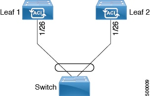
Configuring Virtual Port Channels in Leaf Nodes Using the NX-OS CLI
A virtual Port Channels (vPC) is an enhancement to port-channels that allows connection of a host or switch to two upstream leaf nodes to improve bandwidth utilization and availability. In NX-OS, vPC configuration is done in each of the two upstream switches and configuration is synchronized using peer link between the switches. The ACI model does not require a peer link and vPC configuration can be done globally for both the upstream leaf nodes. A global configuration mode called vpc context is introduced in ACI and vPC interfaces are represented using a type interface vpc that allows global configuration applicable to both leaf nodes.
Two different topologies are supported for vPC in the ACI model: vPC using leaf ports and vPC over FEX ports. It is possible to create many vPC interfaces between a pair of leaf nodes and similarly, many vPC interfaces can be created between a pair of FEX modules attached to the leaf node pairs in a straight-through topology.
vPC considerations include:
-
The vPC name used is unique between leaf node pairs. For example, only one vPC 'foo' can be created per leaf pair (with or without FEX).
-
Leaf ports and FEX ports cannot be part of the same vPC.
-
Each FEX module can be part of only one instance of vPC foo.
-
vPC context allows configuration
-
The vPC context mode allows configuration of all vPCs for a given leaf pair. For vPC over FEX, the fex-id pairs must be specified either for the vPC context or along with the vPC interface, as shown in the following two alternative examples.
(config)# vpc context leaf 101 102
(config-vpc)# interface vpc bar fex 101 101
or
(config)# vpc context leaf 101 102 fex 101 101
(config-vpc)# interface vpc bar
In the ACI model, vPC configuration is done in the following steps (as shown in the examples below):
| Command or Action | Purpose | |||
|---|---|---|---|---|
| Step 1 | configure
Example: apic1# configure |
Enters global configuration mode. | ||
| Step 2 | vpc
domain
explicit
domain-id
leaf
node-id1
node-id2
Example: apic1(config)# vpc domain explicit 1 leaf 101 102 |
Configures a vPC domain between a pair of leaf nodes. You can specify the vPC domain ID in the explicit mode along with the leaf node pairs. Alternative commands to configure a vPC domain are as follows:
| ||
| Step 3 |
peer
dead
interval
value
Example: apic1(config-vpc)# peer dead interval 10 |
The interval between hello packets from a neighbor before the router declares the neighbor as down. This value must be the same for all networking devices on a specific network. Specifying a smaller dead interval (seconds) will give faster detection of a neighbor being down and improve convergence, but might cause more routing instability. | ||
| Step 4 | exit
Example: apic1(config-vpc)# exit |
Returns to global configuration mode. | ||
| Step 5 | template
port-channel
channel-name
Example: apic1(config)# template port-channel foo |
Creates a new port-channel or configures an existing port-channel (global configuration). All vPC are configured as port-channels in each leaf pair. The same port-channel name must be used in a leaf pair for the same vPC. This port-channel can be used to create a vPC among one or more pairs of leaf nodes. Each leaf node will have only one instance of this vPC. | ||
| Step 6 |
lacp
mode
active
Example: apic1(config-if)# lacp mode active |
| ||
| Step 7 | exit
Example: apic1(config-if)# exit |
Returns to configure mode. | ||
| Step 8 |
leaf
node-id1
node-id2
Example: apic1(config)# leaf 101-102 |
Specifies the pair of leafs to be configured. | ||
| Step 9 |
interface
type
Example: apic1(config-leaf)# interface ethernet 1/3-4 |
Specifies the interface or range of interfaces that you are configuring to the port-channel. | ||
| Step 10 | [no]
channel-group
channel-name
vpc
Example: apic1(config-leaf-if)# channel-group foo vpc |
Assigns the interface or range of interfaces to the port-channel. Use the keyword no to remove the interface from the port-channel. To change the port-channel assignment on an interface, you can enter the channel-group command without first removing the interface from the previous port-channel.
| ||
| Step 11 | exit
Example: apic1(config-leaf-if)# exit | |||
| Step 12 | exit
Example: apic1(config-leaf)# exit | |||
| Step 13 |
vpc
context
leaf
node-id1
node-id2
Example: apic1(config)# vpc context leaf 101 102 |
The vpc context mode allows configuration of vPC to be applied to both leaf node pairs. | ||
| Step 14 |
interface
vpc
channel-name
Example: apic1(config-vpc)# interface vpc blue fex 102 102 | |||
| Step 15 |
[no]
shutdown
Example: apic1(config-vpc-if)# no shut | (Optional)
Administrative state configuration in the vpc context allows changing the admin state of a vPC with one command for both leaf nodes. |
This example shows how to configure a basic vPC.
apic1(config)# vpc domain explicit 1 leaf	101 102
apic1(config)# template port-channel foo
apic1(config-if)# lacp mode active
apic1(config-if)# exit
apic1(config)# leaf 101-102
apic1(config-leaf)# interface ethernet 1/3-4
apic1(config-leaf-if)# channel-group foo vpc
apic1(config-leaf-if)# exit
This example shows how to configure vPCs with FEX ports.
apic1(config-leaf)# interface ethernet 101/1/1-2
apic1(config-leaf-if)# channel-group bar vpc
apic1(config)# vpc context leaf 101 102
apic1(config-vpc)# interface vpc foo
apic1(config-vpc-if)# exit
apic1(config-vpc)# interface vpc red fex 101 101
apic1(config-vpc-if)# switchport
apic1(config-vpc-if)# exit
apic1(config-vpc)# interface vpc blue fex 102 102
apic1(config-vpc-if)# shut
Basic FEX Configuration
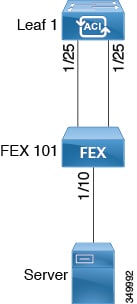
Note | This procedure provides the steps for attaching a server to the FEX. The steps would be the same for attaching any device to an ACI attached FEX. |
-
The ACI fabric is installed, APIC controllers are online, and the APIC cluster is formed and healthy.
-
An APIC fabric administrator account is available that will enable creating the necessary fabric infrastructure configurations.
-
The target leaf switch, interfaces, and protocol(s) are configured and available.
-
The FEX is powered on and connected to the target leaf interfaces
| Step 1 | On the
APIC,
create a switch profile using the
Configure Interface, PC,
And VPC wizard.
Verification: Use the CLI show fex command on the switch where the FEX is attached to verify that the FEX is online. |
| Step 2 | Customize the
auto-generated
FEX
Profile to enable attaching a server to a single FEX port.
Verification: Use the CLI show int command on the switch where the FEX is attached to verify that the FEX interface is configured accordingly. |
What to Do Next
While this
configuration enables hardware connectivity, no data traffic can flow without a
valid application profile, EPG, and contract that is associated with this
hardware configuration.
Note
FEX Port Channel Configuration
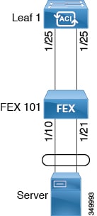
Note | This procedure provides the steps for attaching a server to the FEX port channel. The steps would be the same for attaching any device to an ACI attached FEX. |
-
The ACI fabric is installed, APIC controllers are online, and the APIC cluster is formed and healthy.
-
An APIC fabric administrator account is available that will enable creating the necessary fabric infrastructure configurations.
-
The target leaf switch, interfaces, and protocol(s) are configured and available.
-
The FEX is configured, powered on, and connected to the target leaf interfaces
| Step 1 | On the
APIC,
add a port channel to a FEX profile.
|
| Step 2 | Customize the
Create
Access Port Selector to enable attaching a server to the FEX port
channel.
Verification: Use the CLI show port-channel summary command on the switch where the FEX is attached to verify that the port channel is configured accordingly. |
What to Do Next
While this
configuration enables hardware connectivity, no data traffic can flow without a
valid application profile, EPG, and contract that is associated with this
hardware configuration.
Note
FEX Virtual Port Channel Configuration
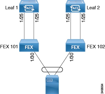
Note | This procedure provides the steps for attaching a server to the FEX virtual port channel. The steps would be the same for attaching any device to an ACI attached FEX. |
-
The ACI fabric is installed, APIC controllers are online, and the APIC cluster is formed and healthy.
-
An APIC fabric administrator account is available that will enable creating the necessary fabric infrastructure configurations.
-
The target leaf switch, interfaces, and protocol(s) are configured and available.
-
The FEXes are configured, powered on, and connected to the target leaf interfaces
| Step 1 | On the
APIC,
add a virtual port channel to two FEX profiles.
|
| Step 2 | Customize the
Create
Access Port Selector to enable attaching a server to the FEX virtual
port channel.
Verification: Use the CLI show port-channel summary command on the switch where the FEX is attached to verify that the port channel is configured accordingly. |
| Step 3 | Configure the
second FEX to use the same
Interface Policy Group just specified for the first
FEX.
Verification: Use the CLI show vpc extended command on the switch where one of the FEXes is attached to verify that the virtual port channel is configured accordingly. |
What to Do Next
While this
configuration enables hardware connectivity, no data traffic can flow without a
valid application profile, EPG, and contract that is associated with this
hardware configuration.
Note
About Traffic Storm Control
A traffic storm occurs when packets flood the LAN, creating excessive traffic and degrading network performance. You can use traffic storm control policies to prevent disruptions on Layer 2 ports by broadcast, unknown multicast, or unknown unicast traffic storms on physical interfaces.
By default, storm control is not enabled in the ACI fabric. ACI bridge domain (BD) Layer 2 unknown unicast flooding is enabled by default within the BD but can be disabled by an administrator. In that case, a storm control policy only applies to broadcast and unknown multicast traffic. If Layer 2 unknown unicast flooding is enabled in a BD, then a storm control policy applies to Layer 2 unknown unicast flooding in addition to broadcast and unknown multicast traffic.
Traffic storm control (also called traffic suppression) allows you to monitor the levels of incoming broadcast, multicast, and unknown unicast traffic over a one second interval. During this interval, the traffic level, which is expressed either as percentage of the total available bandwidth of the port or as the maximum packets per second allowed on the given port, is compared with the traffic storm control level that you configured. When the ingress traffic reaches the traffic storm control level that is configured on the port, traffic storm control drops the traffic until the interval ends. An administrator can configure a monitoring policy to raise a fault when a storm control threshold is exceeded.
- Storm Control Guidelines
- Configuring a Traffic Storm Control Policy Using the GUI
- Configuring a Traffic Storm Control Policy Using the REST API
- Configuring a Traffic Storm Control Policy Using the NX-OS Like CLI
Storm Control Guidelines
Configure traffic storm control levels according to the following guidelines and limitations:
-
Typically, a fabric administrator configures storm control in fabric access policies on the following interfaces:
-
For port channels and virtual port channels, the storm control values (packets per second or percentage) apply to all individual members of the port channel. Do not configure storm control on interfaces that are members of a port channel.
Note
On switch hardware starting with the APIC 1.3(x) and switch 11.3(x) release, for port channel configurations, the traffic suppression on the aggregated port may be up to two times the configured value. The new hardware ports are internally subdivided into these two groups: slice-0 and slice-1. To check the slicing map, use the vsh_lc command show platform internal hal l2 port gpd and look for slice 0 or slice 1 under the Sl column. If port-channel members fall on both slice-0 and slice-1, allowed storm control traffic may become twice the configured value because the formula is calculated based on each slice.
-
When configuring by percentage of available bandwidth, a value of 100 means no traffic storm control and a value of 0.01 suppresses all traffic.
-
Due to hardware limitations and the method by which packets of different sizes are counted, the level percentage is an approximation. Depending on the sizes of the frames that make up the incoming traffic, the actual enforced level might differ from the configured level by several percentage points. Packets-per-second (PPS) values are converted to percentage based on 256 bytes.
-
Maximum burst is the maximum accumulation of rate that is allowed when no traffic passes. When traffic starts, all the traffic up to the accumulated rate is allowed in the first interval. In subsequent intervals, traffic is allowed only up to the configured rate. The maximum supported is 65535 KB. If the configured rate exceeds this value, it is capped at this value for both PPS and percentage.
-
The maximum burst that can be accumulated is 512 MB.
-
On an egress leaf switch in optimized multicast flooding (OMF) mode, traffic storm control will not be applied.
-
On an egress leaf switch in non-OMF mode, traffic storm control will be applied.
-
On a leaf switch for FEX, traffic storm control is not available on host-facing interfaces.
Configuring a Traffic Storm Control Policy Using the GUI
| Step 1 | In the menu bar, click Fabric. |
| Step 2 | In the submenu bar, click Access Policies. |
| Step 3 | In the Navigation pane, expand Interface Policies. |
| Step 4 | Expand Policies. |
| Step 5 | Right-click Storm Control and choose Create Storm Control Interface Policy. |
| Step 6 | In the Create Storm Control Interface Policy dialog box, enter a name for the policy in the Name field. |
| Step 7 | In the Specify Policy In field, click the radio button for either Percentage or Packets Per Second. |
| Step 8 | If you chose
Percentage, perform the following steps:
|
| Step 9 | If you chose
Packets
Per Second, perform the following steps:
|
| Step 10 | Click Submit. |
| Step 11 | Apply the storm
control interface policy to an interface port.
|
Configuring a Traffic Storm Control Policy Using the REST API
To configure a traffic storm control policy, create a stormctrl:IfPol object with the desired properties.
To create a policy named MyStormPolicy, send this HTTP POST message:
POST https://192.0.20.123/api/mo/uni/infra/stormctrlifp-MyStormPolicy.json
In the body of the POST message, Include the following JSON payload structure to specify the policy by percentage of available bandwidth:
{"stormctrlIfPol":
    {"attributes":
        {"dn":"uni/infra/stormctrlifp-MyStormPolicy",
        "name":"MyStormPolicy",
        "rate":"75",
        "burstRate":"85",
        "rn":"stormctrlifp-MyStormPolicy",
        "status":"created"
        },
        "children":[]
    }
}
In the body of the POST message, Include the following JSON payload structure to specify the policy by packets per second:
{"stormctrlIfPol":
    {"attributes":
        {"dn":"uni/infra/stormctrlifp-MyStormPolicy",
        "name":"MyStormPolicy",
        "ratePps":"12000",
        "burstPps":"15000",
        "rn":"stormctrlifp-MyStormPolicy",
        "status":"created"
        },
        "children":[]
    }
}
Apply the traffic storm control interface policy to an interface port.
POST http://192.0.20.123/api/node/mo/uni/infra/funcprof/accportgrp-InterfacePolicyGroup/rsstormctrlIfPol.json
In the body of the POST message, Include the following JSON payload structure to apply the policy to the interface policy group.
{"infraRsStormctrlIfPol":{"attributes":{"tnStormctrlIfPolName":"testStormControl"},"children":[]}}
Configuring a Traffic Storm Control Policy Using the NX-OS Like CLI
| Command or Action | Purpose |
|---|
(config)# template policy-group pg2
(config-pol-grp-if)# storm-control level 50 burst-rate 60
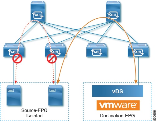
Intra-EPG Endpoint Isolation
Intra-EPG endpoint isolation policies provide full isolation for virtual or physical endpoints; no communication is allowed between endpoints in an EPG that is operating with isolation enforced. Isolation enforced EPGs reduce the number of EPG encapsulations required when many clients access a common service but are not allowed to communicate with each other.
An EPG is isolation enforced for all ACI network domains or none. While the ACI fabric implements isolation directly to connected endpoints, switches connected to the fabric are made aware of isolation rules according to a primary VLAN (PVLAN) tag.
Note | If an EPG is configured with intra-EPG endpoint isolation enforced, these restrictions apply:
|
Intra-EPG Isolation for Bare Metal Servers
Intra-EPG endpoint isolation policies can be applied to directly connected endpoints such as bare metal servers.
-
Backup clients have the same communication requirements for accessing the backup service, buy they don't need to communicate with each other.
-
Servers behind a load balancer have the same communication requirements, but isolating them from each other protects against a server that is compromised or infected.
Bare metal EPG isolation is enforced at the leaf switch. Bare metal servers use VLAN encapsulation. All unicast, multicast and broadcast traffic is dropped (denied) within isolation enforced EPGs. ACI bridge-domains can have a mix of isolated and regular EPGs. Each Isolated EPG can have multiple VLANs where intra-vlan traffic is denied.
- Using the GUI to Configure Intra-EPG Isolation for Bare Metal Servers
- Using the NX-OS Style CLI to Configure Intra-EPG Isolation for Bare Metal Servers
- Using the REST API to Configure Intra-EPG Isolation for Bare Metal Servers
Using the GUI to Configure Intra-EPG Isolation for Bare Metal Servers
The port the EPG uses must be associated with a bare metal server interface in the physical domain that is used to connect the bare metal servers directly to leaf switches.
Using the NX-OS Style CLI to Configure Intra-EPG Isolation for Bare Metal Servers
| Command or Action | Purpose | |
|---|---|---|
| Step 1 | In the CLI,
create an intra-EPG isolation EPG:
Example: The VMM case is below. ifav19-ifc1(config)# tenant Test_Isolation
ifav19-ifc1(config-tenant)# application PVLAN
ifav19-ifc1(config-tenant-app)# epg EPG1
ifav19-ifc1(config-tenant-app-epg)# show running-config
# Command: show running-config
tenant Test_Isolation
application PVLAN epg EPG1
tenant Test_Isolation
application PVLAN
epg EPG1
bridge-domain member BD1
contract consumer bare-metal
contract consumer default
contract provider Isolate_EPG
isolation enforce <---- This enables EPG isolation mode.
exit
exit
ifav19-ifc1(config)# leaf ifav19-leaf3
ifav19-ifc1(config-leaf)# interface ethernet 1/16
ifav19-ifc1(config-leaf-if)# show running-config
ifav19-ifc1(config-leaf-if)# switchport trunk native vlan 101 tenant Test_Isolation application PVLAN epg StaticEPG primary-vlan 100
exit
| |
| Step 2 | Verify the
configuration:
Example: show epg StaticEPG detail Application EPg Data: Tenant : Test_Isolation Application : PVLAN AEPg : StaticEPG BD : BD1 uSeg EPG : no Intra EPG Isolation : enforced Vlan Domains : phys Consumed Contracts : bare-metal Provided Contracts : default,Isolate_EPG Denied Contracts : Qos Class : unspecified Tag List : VMM Domains: Domain Type Deployment Immediacy Resolution Immediacy State Encap Primary Encap -------------------- --------- -------------------- -------------------- -------------- ---------- ---------- DVS1 VMware On Demand immediate formed auto auto Static Leaves: Node Encap Deployment Immediacy Mode Modification Time ---------- ---------------- -------------------- ------------------ ------------------------------ Static Paths: Node Interface Encap Modification Time ---------- ------------------------------ ---------------- ------------------------------ 1018 eth101/1/1 vlan-100 2016-02-11T18:39:02.337-08:00 1019 eth1/16 vlan-101 2016-02-11T18:39:02.337-08:00 Static Endpoints: Node Interface Encap End Point MAC End Point IP Address Modification Time ---------- ------------------------------ ---------------- ----------------- ------------------------------ ------------------------------ |
Using the REST API to Configure Intra-EPG Isolation for Bare Metal Servers
The port the EPG uses must be associated with a bare metal server interface in the physical domain.
| Step 1 | Send this HTTP POST message to deploy the application using the XML API. Example: POST https://192.0.20.123/api/mo/uni/tn-ExampleCorp.xml |
| Step 2 | Include this XML structure in the body of the POST message.
Example: <fvTenant name="Tenant_BareMetal" > <fvAp name="Web"> <fvAEPg name="IntraEPGDeny" pcEnfPref="enforced"> <!-- pcEnfPref="enforced" ENABLES ISOLATION--> <fvRsBd tnFvBDName="bd" /> <fvRsDomAtt tDn="uni/phys-Dom1" /> <!-- PATH ASSOCIATION --> <fvRsPathAtt tDn="topology/pod-1/paths-1017/pathep-[eth1/2]" encap="vlan-51" primaryEncap="vlan-100" instrImedcy='immediate'/> </fvAEPg> </fvAp> </fvTenant> |
 Feedback