Cisco CGS 2520 Switch Software Configuration Guide for IOS Release 12.2(58)EY
Available Languages
Table Of Contents
Cisco Connected Grid Switch Software Configuration Guide, Cisco IOS Release 12.2(58)EY
Cisco IOS Release 12.2(58)EY Features
IEEE 1588 Precision Time Protocol
Power Profile Modes on the Switch
PTP Clock Modes Supported on the Switch
Switch Configuration Guidelines for PTP
Configuring PTP Power Profile Mode on the Switch
Configuring Non-Power Profile Mode on the Switch
Tagging Behavior for PTP Packets
Temperature and Voltage Monitoring
Power Supply Voltage Monitoring
Monitoring and Storing Temperature and Voltage Data
Configuring Temperature and Voltage Monitoring Options
Configure Temperature Monitoring Features
Configure Power Supply Monitoring Features
Configure RPS Monitoring Features
Temperature and Voltage Monitoring Show Commands
Enable Entity Sensor Threshold Notifications
Specify SNMP Notification Recipients
Bidirectional Forwarding Detection Protocol
Configuring BFD Session Parameters on an Interface
Enabling BFD Routing Protocol Clients
Cisco Connected Grid Switch Software Configuration Guide, Cisco IOS Release 12.2(58)EY
Publication Date: July 5, 2011This guide provides configuration information about the software features released in Cisco IOS Release 12.2(58)EY. This software release is supported on the Connected Grid switch devices listed in the section Supported Hardware. This document should be used in conjunction with the related software documentation the supported devices
Tell Us What You Think
Supported Hardware
Cisco CGS 2520 Switch
Cisco IOS Release 12.2(53)EX
Cisco 2500 Series Connected Grid Switches Configuration Guides
Cisco IOS Release 12.2(58)EY Features
The following are the software features described in this guide:
•
IEEE 1588 Precision Time Protocol
•
•
IEEE 1588 Precision Time Protocol
This section describes Precision Time Protocol (PTP) and how to configure it on the switch. This section includes following topics:
•
•
About Precision Time Protocol
Precision Time Protocol (PTP) is defined in IEEE-1588 as Precision Clock Synchronization for Networked Measurements and Control Systems, and was developed to synchronize the clocks in packet-based networks that include distributed device clocks of varying precision and stability. PTP is designed specifically for industrial, networked measurement and control systems, and is optimal for use in distributed systems because it requires minimal bandwidth and little overhead processing.

Note
Why PTP?
Smart grid power automation applications such as peak-hour billing, virtual power generators, and outage monitoring and management, require extremely precise time accuracy and stability. Timing precision improves network monitoring accuracy and troubleshooting ability.
In addition to providing time accuracy and synchronization, the PTP message-based protocol can be implemented on packet-based networks, such as Ethernet networks. The benefits of using PTP in an Ethernet network include:
•
•
Ethernet Switches and Delays
In an Ethernet network, switches provide a full-duplex communication path between network devices. Switches send data packets to packet destinations using address information contained in the packets. When the switch attempts to send multiple packets simultaneously, some of the packets are buffered by the switch so that they are not lost before they are sent. When the buffer is full, the switch delays sending packets. This delay can cause device clocks on the network lose synchronization with one another.
Additional delays can occur when packets entering a switch are stored in local memory while the switch searches the MAC address table to verify packet CRC fields. This process causes variations in packet forwarding time latency, and these variations can result in asymmetrical packet delay times.
Adding PTP to a network can compensate for these latency and delay problems by correctly adjusting device clocks so that they stay synchronized with one another. PTP enables network switches to function as PTP devices, including boundary clocks and transparent clocks.
Note
Message-Based Synchronization
To ensure clock synchronization, PTP requires an accurate measurement of the communication path delay between the time source (master) and the receiver (slave). PTP sends messages between the master and slave device to determine the delay measurement. Then PTP measures the exact message transmit time and receive times and uses these times to calculate the communication path delay. PTP then adjusts current time information contained in network data for the calculated delay, resulting in more accurate time information.
This delay measurement principle determines path delay between devices on the network and the local clocks are adjusted for this delay using a series of messages sent between masters and slaves. The one-way delay time is calculated by averaging the path delay of the transmit and receive messages. This calculation assumes a symmetrical communication path; however, switched networks do not necessarily have symmetrical communication paths, due to the buffering process.
PTP provides a method, using transparent clocks, to measure and account for the delay in a time-interval field in network timing packets, making the switches temporarily transparent to the master and slave nodes on the network. An end-to-end transparent clock forwards all messages on the network in the same way that a switch does.
More Information
•
•
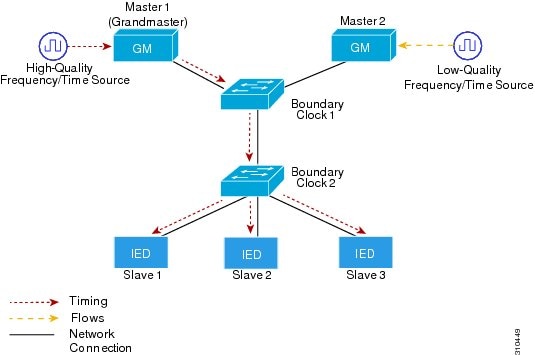
Figure 1 shows a typical 1588 PTP network that includes grandmaster clocks, switches in boundary clock mode, and Intelligent Electronic Device (IEDs) such as a digital relays or protection devices. In this diagram, Master 1 is the grandmaster clock. If Master 1 becomes unavailable, the boundary clock slaves switch to Master 2 for synchronization.
Figure 1 PTP Network
PTP Event Message Sequences
This section describes the PTP event message sequences that occur during synchronization.
Synchronizing with Boundary Clocks
The ordinary and boundary clocks configured for the delay request-response mechanism use the following event messages to generate and communicate timing information:
•
•
•
•
These messages are sent in the following sequence:
1.
2.
3.
4.
5.
6.
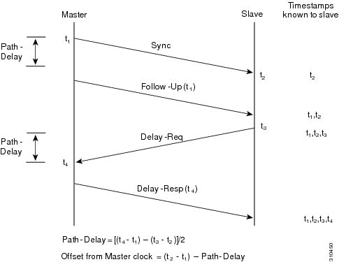
After this sequence, the slave possesses all four timestamps. These timestamps can be used to compute the offset of the slave clock relative to the master, and the mean propagation time of messages between the two clocks.
The offset calculation is based on the assumption that the time for the message to propagate from master to slave is the same as the time required from slave to master. This assumption is not always valid on an Ethernet network, due to asymmetrical packet delay times.
Figure 2 Detailed Steps—Boundary Clock Synchronization
Synchronizing with Peer-to-Peer Transparent Clocks
When the network includes multiple levels of boundary clocks in the hierarchy, with non-PTP enabled devices between them, synchronization accuracy decreases.
The round-trip time is assumed to be equal to mean_path_delay/2, however this is not always valid for Ethernet networks. To improve accuracy, the resident time of each intermediary clock is added to the offset in the end-to-end transparent clock. Resident time, however, does not take into consideration the link delay between peers, which is handled by peer-to-peer transparent clocks.
Peer-to-peer transparent clocks measure the link delay between two clock ports implementing the peer delay mechanism. The link delay is used to correct timing information in Sync and Follow_Up messages.
Peer-to-peer transparent clocks use the following event messages:
•
•
•
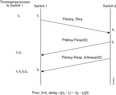
These messages are sent in the following sequence:
1.
2.
3.
To minimize errors due to any frequency offset between the two ports, Port 2 returns the Pdelay_Resp message as quickly as possible after the receipt of the Pdelay_Req message.
4.
5.
Figure 3 Detailed Steps—Peer-to-Peer Transparent Clock Synchronization
Synchronizing the Local Clock
In an ideal PTP network, the master and slave clock operate at the same frequency. However, drift can occur on the network. Drift is the frequency difference between the master and slave clock. You can compensate for drift by using the time stamp information in the device hardware and follow-up messages (intercepted by the switch) to adjust the frequency of the local clock to match the frequency of the master clock.
Best Master Clock Algorithm
The Best Master Clock (BMC) algorithm is the basis of PTP functionality. BMC specifies how each clock on the network determines the best master clock in its subdomain of all the clocks it can see, including itself. The BMC algorithm runs on the network continuously and quickly adjusts for changes in network configuration.
BMC uses the following criteria to determine the best master clock in the subdomain:
•
•
•
•
In addition to identifying the best master clock, BMC also ensures that clock conflicts do not occur on the PTP network by ensuring that:
•
•
PTP Clocks
A PTP network is made up of PTP-enabled devices and devices that are not using PTP. The PTP-enabled devices typically consist of the following clock types, which are described in this section:
Grandmaster Clock
Within a PTP domain, the grandmaster clock is the primary source of time for clock synchronization using PTP. The grandmaster clock usually has a very precise time source, such as a GPS or atomic clock. When the network does not require any external time reference and only needs to be synchronized internally, the grandmaster clock can free run.
Ordinary Clock
An ordinary clock is a PTP clock with a single PTP port. It functions as a node in a PTP network and can be selected by BMC as a master or slave within a subdomain. Ordinary clocks are the most common clock type on a PTP network because they are used as end nodes on a network that is connected to devices requiring synchronization. Ordinary clocks have various interface to external devices.
Boundary Clock
A boundary clock in a PTP network operates in place of a standard network switch or router. Boundary clocks have more than one PTP port, and each port provides access to a separate PTP communication path. Boundary clocks provide an interface between PTP domains. They intercept and process all PTP messages, and pass all other network traffic. The boundary clock uses the BMC algorithm to select the best clock seen by any port. The selected port is then set as a slave. The master port synchronizes the clocks connected downstream, while the slave port synchronizes with the upstream master clock.
Transparent Clock
The role of transparent clocks in a PTP network is to update the time-interval field that is part of the PTP event message. This update compensates for switch delay and has an accuracy of within one picosecond.
There are two types of transparent clocks:
End-to-end (E2E) transparent clocks measure the PTP event message transit time (also known as resident time) for SYNC and DELAY_REQUEST messages. This measured transit time is added to a data field (correction field) in the corresponding messages:
•
•
The slave uses this information when determining the offset between the slave's and the master's time. E2E transparent clocks do not provide correction for the propagation delay of the link itself.
Peer-to-peer (P2P) transparent clocks measure PTP event message transit time in the same way E2E transparent clocks do, as described above. In addition, P2P transparent clocks measure the upstream link delay. The upstream link delay is the estimated packet propagation delay between the upstream neighbor P2P transparent clock and the P2P transparent clock under consideration.
These two times (message transit time and upstream link delay time) are both added to the correction field of the PTP event message, and the correction field of the message received by the slave contains the sum of all link delays. In theory this is the total end-to-end delay (from master to slave) of the SYNC packet.
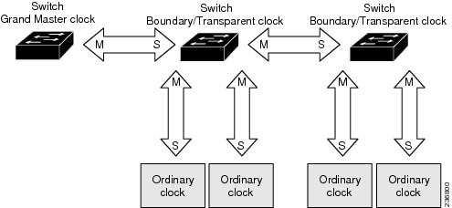
Figure 4 illustrates PTP clocks in a master-slave hierarchy within a PTP network.
Figure 4 PTP Clock Hierarchy
About the PTP Power Profile
This section describes PTP profiles and specifically the PC37.238 IEEE-1588 standard, Power Profile, which is also known as the Profile for Protection Applications.
Note
What are PTP Profiles?
The IEEE-1588 definition of a PTP profile is the set of allowed PTP features applicable to a device. A PTP profile is usually specific to a particular type of application or environment and defines the following values:
•
•
•
•
•
•
•
Power Profile Description
The IEEE Power Profile defines specific or allowed values for PTP networks used in power substations. The defined values include the optimum physical layer, the higher level protocol for PTP messages, and the preferred best master clock algorithm. The Power Profile values ensure consistent and reliable network time distribution within substations, between substations, and across wide geographic areas.
The switch is optimized for PTP in these ways:
•
•
Table 1 lists the configuration values defined by the IEEE-1588 Power Profile.
Table 1 Configuration Values for the IEEE PTP Power Profile and Switch Modes
Message transmission
Ethernet 802.3, with Ethertype 0X88F7. PTP messages are sent as 802.1Q tagged Ethernet frames with a default VLAN 0 and default priority 4.
Access Ports-Untagged Layer 2 packets,
Trunk Ports-802.1Q tagged Layer 2 packets with native VLAN on the port and default priority value of 4.
Layer 3 packets. By default, 802.1q tagging is disabled.
MAC address-Non-peer delay messages
01-1B-19-00-00-00.
01-1B-19-00-00-00.
01-1B-19-00-00-00.
MAC address-Peer delay messages
01-80-C2-00-00-0E.
01-80-C2-00-00-0E.
Not applicable to this mode.
Domain number
0.
0.
0.
Path delay calculation
Peer-to-peer transparent clocks.
Peer-to-peer transparent clocks using the peer_delay mechanism.
End-to-end transparent clocks using the delay_request mechanism.
BMC
Enabled.
Enabled.
Enabled.
Clock type
Two-step and one-step clocks are supported. Two-step is preferred for Ethernet.
Two-step.
Two-step.
Time scale
Epoch.1
Epoch.
Epoch.
Grandmaster ID and local time determination
PTP-specific TLV (type, length, value) to indicate Grandmaster ID.
PTP-specific TLV to indicate Grandmaster ID.
PTP-specific type, length, and value to indicate Grandmaster ID.
Time accuracy over network hops
Over 16 hops, slave device synchronization accuracy is within 1 usec (1 microsecond).
Over 16 hops, slave device synchronization accuracy is within 1 usec (1 microsecond).
Not applicable in this mode.
1 Epoch = Elapsed time since epoch start.
Configuring PTP on the Switch
This section describes how to configure the switch for PTP applications.
Power Profile Modes on the Switch
This section describes the two PTP modes that the switch uses.
Note
Power Profile Mode
By default, the switch PTP configuration uses the values defined by the IEEE-1588 Power Profile and the switch is in power profile mode. In this mode:
•
•
Table 1 lists the configuration values for the switch in power profile mode.
Non-Power Profile Mode
When power profile mode is disabled on the switch with the no ptp profile power command, the switch is in non-power profile mode. In this mode:
•
•
Table 1 lists the configuration values for the switch in non-power profile mode.
PTP Clock Modes Supported on the Switch
PTP synchronization behavior depends on the PTP clock mode that you configure on the switch. You can configure the switch for one of the following global modes:
Boundary Clock Mode
A switch configured for boundary clock mode participates in selecting the best master clock on the subdomain, selecting from all clocks it can see, including itself. If the switch does not detect a more accurate clock than itself, then the switch becomes the master clock. If a more accurate clock is detected, then the switch synchronizes to that clock and becomes a slave clock.
After initial synchronization, the switch and the connected devices exchange PTP timing messages to correct the changes caused by clock offsets and network delays. These are some guidelines for this mode:
•
•
Forward Mode
A switch configured for forward mode passes incoming PTP packets as normal multicast traffic. These are some guidelines for this mode:
•
•
•
E2E Transparent Clock Mode
A switch configured for end-to-end transparent clock mode does not synchronize its clock with the master clock. A switch in this mode does not participate in master clock selection and uses the default PTP clock mode on all ports. These are some guidelines for this mode
•
•
•
P2P Transparent Clock Mode
A switch configured for peer-to-peer transparent clock mode does not synchronize its clock with the master clock. A switch in this mode does not participate in master clock selection and uses the default PTP clock mode on all ports. These are some guidelines for this mode:
•
•
•
Switch Configuration Guidelines for PTP
Be aware of the guidelines in this section when you configure PTP on the switch.
PTP Mode and Profile Guidelines
•
•
•
•
•
If the grandmaster clock is not compliant with PTP and sends announce messages without these TLVs, configure the switch to process the announce message by entering the ptp allow-without-tlv command.
Refer to the section Configuring PTP Power Profile Mode on the Switch, for a complete description of this command.
•
To change to Boundary Clock Mode and the peer_delay mechanism, enter the ptp mode boundary pdelay-req command.
•
Refer to the section Configuring Non-Power Profile Mode on the Switch, for a complete description of this command.
•
To change to Boundary Clock Mode with the delay_request mechanism, enter the ptp mode boundary delay-req command.
Packet Format Guidelines
•
•
•
–
–
•
•
VLAN Configuration Guidelines
•
•
Clock Configuration Guidelines
•
•
•
Configuring PTP Power Profile Mode on the Switch
This section describes how to configure the switch to use the PTP Power Profile and operate in power profile mode.
•
•
Before You Begin
These are some guidelines for configuring the Power Profile on the switch:
•
•
To configure the switch for power profile mode, follow these steps:
Step 1
configure terminal
Enters global configuration mode.
Step 2
ptp profile power
Enables the PTP Power Profile on the switch and configures the switch for power profile mode (if the switch is in non-power profile mode). The switch default configuration is power profile enabled. If the switch is already in power profile mode, then this command has no effect.
Step 3
ptp {allow-without-tlv | domain | mode {boundary pdelay-req | p2ptransparent | forward} | packet | priority1 priority | priority2 priority}
Specifies the synchronization clock mode.
•
•
•
•
•
The following options specify the clock priority properties when the switch port is in boundary mode.
•
•
•
•
Step 4
interface interface-id
Enters interface configuration mode.
Step 5
ptp {announce interval {interval} | timeout {timeout-in-secs} | delay-req {interval interval} | enable | pdelay-req {interval interval} | sync {interval interval} | limit {offset-in-nanosecs}}
Specifies the settings for PTP timing messages. These options are available only when the switch is in boundary mode.
•
•
•
•
•
•
•
•
Step 6
end
Returns to privileged EXEC mode.
Step 7
show running-config
Verifies your entries.
Step 8
copy running-config startup-config
(Optional) Saves your entries in the configuration file.
Configuring Non-Power Profile Mode on the Switch
This section describes how to configure the switch to operate in non-power profile mode.
•
•
Before You Begin
The switch sends untagged PTP packets on the native VLAN when the switch port connected to the grandmaster clock is configured as follows:
•
•
•
When the grandmaster clock requires tagged packets, make one of the following configuration changes:
•
•
To configure the switch for non-power profile mode, follow these steps:
Step 1
configure terminal
Enters global configuration mode.
Step 2
no ptp profile power
Configures the switch for non-power profile mode when the switch is in power profile mode. If the switch is already in non-power profile mode, this command has no effect.
Step 3
ptp {domain | mode boundary delay-req | e2etransparent | forward} | packet | priority1 priority | priority2 priority}
Specifies the synchronization clock.
•
•
•
•
These options specify the clock priority properties when the switch port is in boundary mode:
•
•
•
•
Step 4
interface interface-id
Enters interface configuration mode.
Step 5
ptp {announce {interval interval | timeout interval} | delay-req interval interval | enable | sync {interval interval | limit offset-in-nanosecs}}
Specifies the settings for the timing messages. These options are available only when the switch is in boundary mode.
•
•
•
•
•
•
•
Step 6
end
Returns to privileged EXEC mode.
Step 7
show running-config
Verifies your entries.
Step 8
copy running-config startup-config
(Optional) Saves your entries in the configuration file.
PTP Show Commands
This section describes the PTP show command options.
Tagging Behavior for PTP Packets
Table 2 describes the switch tagging behavior in power profile and non-power profile modes.
Table 2 Tagging Behavior for PTP Packets
Temperature and Voltage Monitoring
Cisco IOS Release 12.2(28)EY includes enhancements to features that support monitoring of the switch operating temperature and power supply voltage. This section describes how to configure this feature on the switch, and includes the following topics:
•
•
•
Power Supply Voltage Monitoring
Earlier software releases for the switch supported user configurable alarm thresholds (maximum and minimum) for the switch operating temperature. You can configure operating temperature ranges (primary and secondary) for the switch, and then configure alarm options to trigger an event message when the switch operating temperature is out of the defined range.
Cisco IOS Release 12.2(58)EY includes a similar feature for the switch power supply. You can configure power supply voltage ranges and then configure alarm options for when the voltage is out of range. These features include:
•
•
Historical Data Collection
Cisco IOS Release 12.2(58)EY includes new features to support switch historical data collection and storage. Use these features to configure the switch to save historical data about switch operating temperature and power supply voltage. New features include:
•
•
•
•
Monitoring and Storing Temperature and Voltage Data
This section describes how often the switch monitors and stores temperature and voltage data.
Monitoring Interval
The switch checks the operating temperature and power supply voltage once per minute.
Storage Interval
The switch stores temperature and voltage data as follows:
•
•
You must enter the alarm facility history command to enable the switch to store the data that it collects at the monitoring intervals. Refer to these sections for details about how to use these commands:
•
•
Maximum Storage Period
The switch stores temperature and voltage data for a maximum of 72 hours. After 72 hours, the oldest data is purged as the switch adds the most recent data.
Alarms
At each monitoring interval, the switch checks the operating temperature and power supply voltage. If the switch detects that either is out of range of the thresholds defined with the alarm facility command, then it generates an event message (alarm). The message type is SYSLOG or SNMP trap. Refer to these sections for details about how to use these commands:
•
•
•
Configuring Temperature and Voltage Monitoring Options
This section describes the temperature and voltage monitoring configuration commands supported in Cisco IOS Release 12.2(58)EY and later.
Configure Temperature Monitoring Features
Use the alarm facility temperature global configuration command to configure temperature thresholds for the purpose of generating event messages (alarms). You can configure an alarm for both of these threshold types.
You can also use this command to:
•
•
•
•
Switch)# no alarm facility temperature primary low 220
Configure Power Supply Monitoring Features
Supported Power Supplies
The switch supports the power supply models described below. The alarm facility power-supply voltage command options and alarm threshold ranges are different for each model.
For detailed information about these power supplies, refer to the switch hardware installation guide.
Use the alarm facility power-supply voltage global configuration command to configure voltage thresholds for the purpose of generating event messages (alarms). You can also use this command to:
•
•
•
•
Configure RPS Monitoring Features
Use the alarm facility power-supply rps global configuration command to configure event messages (alarms) for the switch redundant power supply (RPS). Use this command to:
•
•
•
•
Temperature and Voltage Monitoring Show Commands
This section describes the temperature and voltage monitoring show commands supported in Cisco IOS Release 12.2(58)EY and later.
MIB Support for TVM
This section describes the MIBs that are supported by the TVM feature:
•
•
–
–
–
–
–
Note
Enable Entity Sensor Threshold Notifications
To enable entity sensor threshold notifications, enter the snmp-server enable traps entity-sensor threshold global configuration command. To disable entity sensor threshold notifications, enter the no form of this command.
Specify SNMP Notification Recipients
To specify the recipient of an SNMP notification operation for entity sensor threshold, enter the snmp-server host global configuration command. To remove the specified host, enter the no form of this command.
Bidirectional Forwarding Detection Protocol
The Bidirectional Forwarding Detection (BFD) Protocol quickly detects forwarding-path failures for a variety of media types, encapsulations, topologies, and routing protocols. It operates in a unicast, point-to-point mode on top of any data protocol being forwarded between two systems to track IPv4 connectivity between directly connected neighbors. BFD packets are encapsulated in UDP packets with a destination port number of 3784 or 3785.
BFD over Switched Virtual Interfaces
BFD is supported on physical interfaces that are configured as routing interfaces. Starting with Cisco IOS release 12.2(55)SE, BFD is also supported on Switched Virtual Interfaces (SVIs).
In EIGRP, IS-IS, and OSPF deployments, the closest alternative to BFD is the use of modified failure-detection mechanisms. Although reducing the EIGRP, IS-IS, and OSPF timers can result in a failure-detection rate of 1 to 2 seconds, BFD can provide failure detection in less than 1 second. BFD can be less CPU-intensive than the reduced timers and, because it is not tied to any particular routing protocol, it can be used as a generic and consistent failure detection mechanism for multiple routing protocols.
To create a BFD session, you must configure BFD on both systems (BFD peers). Enabling BFD at the interface and routing protocol level on BFD peers creates a BFD session. BFD timers are negotiated and the BFD peers send control packets to each other at the negotiated intervals. If the neighbor is not directly connected, BFD neighbor registration is rejected.
Figure 1-5 shows a simple network with two routers running OSPF and BFD. When OSPF discovers a neighbor (1), it sends a request to the BFD process to initiate a BFD neighbor session with the neighbor OSPF router (2), establishing the BFD neighbor session (3).
Figure 1-5 Establishing a BFD Session
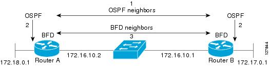
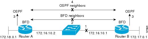
Figure 1-6 shows what happens when a failure occurs in the network (1). The BFD neighbor session with the OSPF neighbor closes (2). BFD notifies the OSPF process that the BFD neighbor is no longer reachable, and the OSPF process breaks the OSPF neighbor relationship (4). When an alternative path is available, the routers start converging on it.
Figure 1-6 Breaking an OSPF Neighbor Relationship
BFD clients are routing protocols that register neighbors with BFD. The switch supports ISIS, OSPF v1 and v2, BGP, EIGRP, and HSRP clients. You can use one BFD session for multiple client protocols. For example, when a network is running OSPF and EIGRP across the same link to the same peer, you need to create only one BFD session, and information is shared with both routing protocols.
The switch supports BFD version 0 and version 1. BFD neighbors automatically negotiate the version and the protocol always runs at the higher version. The default version is version 1.
By default, BFD neighbors exchange both control packets and echo packets for detecting forwarding failures. The switch sends echo packets at the configured BFD interval rate (from 50 to 999 ms on ports or from 600 to999 ms on switch virtual interfaces), and control packets at the BFD slow-timer rate (from 1000 to 3000 ms).
Failure-rate detection can be faster in BFD echo mode, which is enabled by default when you configure BFD session. In this mode, the switch sends echo packets from the BFD software layer, and the BFD neighbor responds to the echo packets through its fast-switching layer. The echo packets do not reach the BFD neighbor software layer, but are reflected back over the forwarding path for failure detection. You configure the rate at which each BFD interface sends BFD echo packets by entering the bfd interval interface configuration command.
To reduce bandwidth consumption, you can disable the sending of echo packets by entering the no bfd echo interface configuration command (refer to the section Disabling BFD Echo Mode). When BFD echo is disabled at one end of a link, the other end of the link also does not send echo packets and does not reflect back the echo packet. Control packets are used to detect forwarding failures. When BFD echo is disabled, the BFD slow-timer configuration does not apply. In a BFD session running in asynchronous mode, BFD packets are exchanged at a negotiated duration when the session is up and at the BFD slow-timer value when the session is down.
To run BFD on a switch, you need to configure basic BFD interval parameters on BFD interfaces, enable routing on the switch, and enable one or more one routing protocol clients for BFD. You also need to confirm that Cisco Express Forwarding (CEF) is enabled (the default) on participating switches.
For more detailed configuration, see the Bidirectional Forwarding Detection feature module at this URL:
http://www.cisco.com/en/US/docs/ios/12_0s/feature/guide/fs_bfd.html
For details on the commands, use the Master Index to the Cisco IOS Command List for Release 12.4. at this URL:
http://www.cisco.com/en/US/docs/ios/mcl/allreleasemcl/all_book.html
These sections describe how to configure BFD:
•
•
Default BFD Configuration
The default BFD settings are as follows:
•
•
•
•
BFD Configuration Guidelines
The BFD configuration guidelines are as follows:
•
–
–
–
Note
•
•
Note
•
–
–
•
•
•
•
Configuring BFD Session Parameters on an Interface
Before you can start a BFD session on an interface, you must put the interface into Layer 3 mode and set the baseline BFD parameters on it.
Note
Follow these steps in privileged EXEC mode to configure BFD parameters on any interface participating in a BFD session:
To remove the BFD parameter configuration, enter the no bfd interval interface configuration command.
Enabling BFD Routing Protocol Clients
After you configure BFD parameters on an interface, you can start a BFD session for one or more routing protocols. You must first enable routing by entering the ip routing global configuration command on the switch. Note that there can be more than one way to start a BFD session on an interface, depending on the routing protocol.
Configuring BFD for OSPF
When you start BFD sessions for OSPF, OSPF must be running on all participating devices.You can enable BFD support for OSPF by enabling it globally on all OSPF interfaces or by enabling it on one or more interfaces.
Configuring BFD for OSPF Globally
Follow these steps in privileged EXEC mode to configure OSFP BFD globally, and to optionally disable it on specific interfaces:
To disable OSPF BFD on all interfaces, enter the no bfd all-interfaces router configuration command.To disable it on an interface, enter the no ip osfp bfd or the ip ospf bfd disable interface configuration command on the interface.
When you want to run OSPF BFD on only one or a few interfaces, you can enter the ip ospf bfd interface configuration command on those interfaces instead of enabling it globally. See the next procedure.
Note
This is an example of configuring BFD for OSPF on all OSPF interfaces:
Switch(config)# router ospf 109Switch(config-router)# bfd all-interfacesSwitch(config-router)# exitConfiguring BFD for OSPF on an Interface
Follow these steps in privileged EXEC mode to configure OSFP BFD on an individual interface:
To disable OSPF BFD on an interface, enter the no ip osfp bfd or the ip ospf bfd disable interface configuration command on the interface.
This is an example of configuring BFD for OSPF on a single interface:
Switch(config)# router ospf 109Switch(config-router)# exitSwitch(config)# interface gigabitethernet0/1Switch(config-if)# ip ospf bfdConfiguring BFD for IS-IS
When you start BFD sessions for IS-IS, IS-IS must be running on all devices participating in BFD. You can enable BFD support for IS-IS by enabling it globally on all IS-IS interfaces or by enabling it on one or more interfaces.
Configuring BFD for IS-IS Globally
Follow these steps in privileged EXEC mode to configure IS-IS BFD globally, and to optionally disable it on specific interfaces:
To disable IS-IS BFD on all interfaces, enter the no bfd all-interfaces router configuration command. To disable it on the specified interface, enter the no isis bfd or the isis bfd disable interface configuration command on the interface.
When you want to run IS-IS BFD on only a few interfaces, instead of enabling it globally, you can enter the isis bfd interface configuration command on those interfaces. See the next procedure.
Note
%ISIS BFD is reverting to router mode configuration, and remains disabled.
This is an example of setting fast convergence and configuring BFD for IS-IS on all IS-IS interfaces:
Switch(config)# router is-is tag1Switch(config-router)# bfd all-interfacesSwitch(config-router)# exitConfiguring BFD for IS-IS on an Interface
Follow these steps in privileged EXEC mode to configure IS-IS BFD on an individual interface:
To disable IS-IS BFD on an interface, enter the no isis bfd or the isis bfd disable interface configuration command on the interface.
This is an example of configuring BFD for IS-IS on a single interface:
Switch(config)# router is-is tag1Switch(config-router)# exitSwitch(config)# interface gigabitethernet0/1Switch(config-if)# isis bfdConfiguring BFD for BGP
When you start BFD sessions for BGP, BGP must be running on all participating devices. You enter the IP address of the BFD neighbor to enable BFD for BGP.
Follow these steps (in privilege EXEC mode) to enable BGP BFD:
To disable BGP BFD, enter the no neighbor ip-address fall-over bfd router configuration command.
Configuring BFD for EIGRP
When you start BFD sessions for EIGRP, EIGRP must be running on all participating devices.You can enable BFD support for EIGRP by globally enabling it on all EIGRP interfaces or by enabling it on one or more interfaces.
Follow these steps in privileged EXEC mode follow these to configure EIGRP BFD:
To disable EIGRP BFD on all interfaces, enter the no bfd all-interfaces router configuration command. To disable it on an interface, enter the no bfd interface interface-id router configuration command.
Configuring BFD for HSRP
HSRP supports BFD by default; it is globally enabled on all interfaces. If HSRP support is manually disabled, you can reenable it in interface or global configuration mode. All participating devices must have HSRP enabled and CEF enabled (the default).
Follow these steps in privileged EXEC mode to reenable HSRP BFD:
To disable HSRP support for BFD on all interfaces, enter the no standby bfd all-interfaces global configuration command. To disable it on an interface, enter the no standby bfd interface configuration command.
Note
Disabling BFD Echo Mode
When you configure a BFD session, BFD echo mode is enabled by default on BFD interfaces. You can disable echo mode on an interface. When BFD echo is disabled at one end of a link, the other end of the link also does not send echo packets and does not reflect back the echo packet. Control packets are used to detect forwarding failures. When BFD echo is disabled, the BFD slow-timer configuration does not apply. In a BFD session running in asynchronous mode, BFD packets are exchanged at a negotiated duration when the session is up and at the BFD slow-timer value when the session is down.
Follow these steps in privileged EXEC mode to disable echo mode on a BFD interface:
To reenable echo mode on the interface, enter the bfd echo interface configuration command. To reenable echo mode on the switch, enter the bfd echo global configuration command.
Related Documents
•
http://www.cisco.com/en/US/products/ps10978/products_installation_and_configuration_guides_list.html
•
http://www.cisco.com/en/US/products/ps10978/prod_release_notes_list.html
Technical Assistance
Finding Support Information for Platforms and Cisco IOS Software Images
Use Cisco Feature Navigator to find information about platform support and Cisco IOS software image support. Access Cisco Feature Navigator at http://www.cisco.com/go/fn. You must have an account on Cisco.com. If you do not have an account or have forgotten your username or password, click Cancel at the login dialog box and follow the instructions that appear.
Cisco and the Cisco Logo are trademarks of Cisco Systems, Inc. and/or its affiliates in the U.S. and other countries. A listing of Cisco's trademarks can be found at www.cisco.com/go/trademarks. Third party trademarks mentioned are the property of their respective owners. The use of the word partner does not imply a partnership relationship between Cisco and any other company. (1005R)
© 2011 Cisco Systems, Inc. All rights reserved.
 Feedback
Contact Cisco
- Open a Support Case

- (Requires a Cisco Service Contract)