Release Notes for the Cisco CGS 2520 Switch and the CG Ethernet Switch Module, Cisco IOS Release 12.2(58)EY and Later
Available Languages
Table Of Contents
Supported Hardware for 12.2(58)EY and Later
Supported Hardware for Far End Fault Indication (FEFI)
Identifying the Product ID (PID) and Part Number for SFPs
Cisco CGR 2010 Software Requirements
Device Manager System Requirements
Finding the Software Version and Feature Set
Upgrading a Switch Using the CLI
Recovering from a Software Failure
Assigning IP Information to the Switch
Default PTP Profile After Upgrade
Upgrading the GLC-FE-100FX-RGD SFP Module
Auto-Negotiation Configuration in Cisco IOS Release 12.2(53)EX and Later
Configuring the Device Manager and HTTP Server Interface
Bidirectional Forwarding Detection (BFD)
Connectivity Fault Management (CFM)
IP Service Level Agreements (SLAs)
Caveats Resolved in Release 12.2(58)EY2
Caveats Resolved in Release 12.2(58)EY1 and Earlier
Obtaining Documentation and Submitting a Service Request
Release Notes for the
Cisco CGS 2520 Switch and the CGR 2010 ESM for Cisco IOS Release 12.2(58)EY and Later
Publication Date: December 20, 2011Part Number: OL-25118-02These release notes are for Cisco IOS Release 12.2(58)EY and later for the following products:
•
Cisco 2520 Connected Grid Switch (Cisco CGS 2520 Switch)
•
Software Advisory Information
Cisco IOS Release 12.2(58)EY2 resolves these defects, found in Cisco IOS Release 12.2(58)EY1:
•
•
This document contains important information about this software release, including the limitations, restrictions, and caveats that apply to it.
Verify that these release notes are correct for your switch:
•
•
•
Download This Software Release from Cisco.com
You can download the switch software from this site (registered Cisco.com users with a login password):
http://www.cisco.com/cisco/web/download/index.htmlContents
•
•
Tell Us What You Think
System Requirements
This section describes the system requirement for this software release and includes the following topics:
•
•
•
•
Supported Hardware for 12.2(58)EY and Later
Table 1
CGR 2010 ESM and Cisco CGS 2520 Switch—Supported Hardware for 12.2(58)EY and Later
Supported Hardware for Far End Fault Indication (FEFI)
This release includes support for Far End Fault Indication (FEFI). FEFI is supported on the fiber Fast Ethernet SFP interfaces for all switch models. The following SFPs support FEFI:
•
•
•
•
•
•
•
•
•
Identifying the Product ID (PID) and Part Number for SFPs
Verify that the SFPs installed in the switch support FEFI by viewing the SFP Product ID (PID) and part number using the methods in this section,

Note
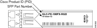
Hardware—Check the SFP Label
Each SFP has a PID and part number on the label. Verify that the PID on the part label is one of the supported SFPs listed in Supported Hardware for Far End Fault Indication (FEFI). If you are using a GLC-FE-100FX-RGD, also verify that the part number ends in -02 or higher. If the part number for a GLC-FE-100FX-RGD ends in -01, the GLC-FE-100FX-RGD does not support FEFI.
Figure 1 Cisco Product ID and Part Number Location on Cisco SFP Modules
Software—Enter the Show Inventory Command
If the SFP is installed in the switch, and you cannot see the label, use the show inventory EXEC command to display information about the switch hardware. These fields are used to determine the Cisco PID and the hardware version:
•
•
Here is example output from the show version command:
CGS2520# show inventoryNAME: "GigabitEthernet0/2", DESCR: "1000BaseSX SFP"PID: GLC-SX-MM-RGD, VID: V01, SN: FNS144600YDNAME: "FastEthernet0/1", DESCR: "100BaseFX-FE SFP"PID: GLC-FE-100FX-RGD, VID: V01, SN: AGP1441C1KHNAME: "FastEthernet0/8", DESCR: "100BaseFX-FE SFP"PID: GLC-FE-100FX-RGD , VID: V02, SN: AGP1520F02JNAME: "FastEthernet0/9", DESCR: "100BaseFX-FE SFP"PID: GLC-FE-100FX-RGD , VID: V02, SN: AGP1520F016NAME: "FastEthernet0/16", DESCR: "100BaseFX-FE SFP"PID: GLC-FE-100FX-RGD , VID: V02, SN: FNS153304E4For detailed instructions on how to use the show inventory command to retrieve the Unique Device Identifier (UDI) information for the switch and other devices that support UDI, refer to the document Unique Device Identifier Retrieval at:
http://www.cisco.com/en/US/docs/ios/12_3t/12_3t4/feature/guide/gtpepudi.html
Cisco CGR 2010 Software Requirements
The Cisco Connected Grid 2010 Router (Cisco CGR 2010) must use a compatible Cisco IOS software release to support the CGR 2010 ESM. Table 3 lists the minimum software release the router requires to support the switch module.
Table 3 Cisco CGR 2010 IOS Release Support for the CGR 2010 ESM
Cisco IOS Release 12.2(58)EY or later
Cisco IOS 15.1(4)M or later
Device Manager System Requirements
The device manager is a web application stored in the switch memory that supports quick configuration. For more information about the device manager, refer to the Cisco CGS 2520 Getting Started Guide. This section includes these topics:
Hardware Requirements
Table 4 Minimum Hardware Requirements
233 MHz minimum1
512 MB2
256
1024 x 768
Small
1 Cisco recommends 1 GHz.
2 Cisco recommends 1 GB DRAM.
Software Requirements
•
•
The device manager verifies the browser version when starting a session, and it does not require a plug-in.
Upgrading the Switch Software
Note
These are the procedures for downloading software. Before downloading software, read this section for important information:
•
•
Finding the Software Version and Feature Set
The Cisco IOS image is stored as a bin file in a directory that is named with the Cisco IOS release. A subdirectory contains the files needed for web management. The image is stored on the compact flash memory card.
You can use the show version privileged EXEC command to see the software version that is running on your switch. The second line of the display shows the version.
You can also use the dir filesystem: privileged EXEC command to see the directory names of other software images that you might have stored in flash memory. For example, use the dir flash: command to display the images in the flash memory.
Deciding Which Files to Use
The upgrade procedures in these release notes describe how to perform the upgrade by using a combined tar file. This file contains the Cisco IOS image file and the files needed for the embedded device manager. You must use the combined tar file to upgrade the switch through the device manager. To upgrade the switch through the command-line interface (CLI), use the tar file and the archive download-sw privileged EXEC command.
Table 5 lists the filenames for this software release.
When you download the IP services image and plan to use Layer 3 functionality, you must use the Switch Database Management (SDM) routing template. To identify the active SDM template, enter the show sdm prefer privileged EXEC command. When necessary, enter the sdm prefer global configuration command to change the SDM template to a specific template. For example, if the switch uses Layer 3 routing, then change the SDM template from the default to the routing template.You must reload the switch for the new template to take effect.
Archiving Software Images
Before upgrading your switch software, make sure that you have archived copies of the current Cisco IOS release and the Cisco IOS release to which you are upgrading. You should keep these archived images until you have upgraded all devices in the network to the new Cisco IOS image and until you have verified that the new Cisco IOS image works properly in your network.
Cisco routinely removes old Cisco IOS versions from Cisco.com. See Product Bulletin 2863 for information:
http://www.cisco.com/en/US/prod/collateral/iosswrel/ps8802/ps6969/ps1835/prod_bulletin0900aecd80281c0e.htmlYou can copy the bin software image file on the flash memory to the appropriate TFTP directory on a host by using the copy flash: tftp: privileged EXEC command.
Note
You can also configure the switch as a TFTP server to copy files from one switch to another without using an external TFTP server by using the tftp-server global configuration command. For more information about the tftp-server command, see the "Basic File Transfer Services Commands" section of the Cisco IOS Configuration Fundamentals Command Reference, Release 12.2:
http://www.cisco.com/en/US/docs/ios/fundamentals/command/reference/cf_t1.htmlUpgrading a Switch Using the CLI
Note
This procedure is for copying the combined tar file to the switch. You copy the file to the switch from a TFTP server and extract the files. You can download an image file and replace or keep the current image.
Note
To download software, follow these steps:
Step 1
Step 2
http://www.cisco.com/kobayashi/sw-center/sw-lan.shtmlStep 3
For more information, see the Cisco CGS 2520 Software Configuration Guide.Step 4
Step 5
Switch# ping tftp-server-addressFor more information about assigning an IP address and default gateway to the switch, see the software configuration guide for this release.
Step 6
Switch# archive download-sw /overwrite /reload
tftp:[[//location]/directory]/image-name.tar
The /overwrite option overwrites the software image in flash memory with the downloaded one.
The /reload option reloads the system after downloading the image unless the configuration has been changed and not saved.
For //location, specify the IP address of the TFTP server.
For /directory/image-name.tar, specify the directory (optional) and the image to download. Directory and image names are case sensitive.
This example shows how to download an image from a TFTP server at 198.30.20.19 and to overwrite the image on the switch:
Switch# archive download-sw /overwrite tftp://198.30.20.19/image-name.tarYou can also download the image file from the TFTP server to the switch and keep the current image by replacing the /overwrite option with the /leave-old-sw option.
Recovering from a Software Failure
For additional recovery procedures, see the "Troubleshooting" chapter in the software configuration guide for this release.
Installation Notes
This section describes things you should be aware of when upgrading the switch to this release, and includes these topics:
•
•
•
Assigning IP Information to the Switch
You can assign IP information to the switch or switch module using these methods. Refer to the document specific for your switch or switch module. See the Related Documentation for document titles and links.
Default PTP Profile After Upgrade
If an earlier version of the switch software is configured to use the PTP default profile (non-power profile mode), upgrading the switch to release 12.2(58)EY2 causes the switch configuration to be changed to use the PTP power profile (power profile mode). Enter the no ptp profile power command to re-configure the switch to use the default PTP profile.
With release 12.2(58)EY2, this issue occurs only during the upgrade process. After the upgrade is complete, any time the switch reboots or reloads, it retains the configured PTP profile.
Note
Upgrading the GLC-FE-100FX-RGD SFP Module
When an older version of SFP module GLC-FE-100FX-RGD is used for the fiber ports in the Fiber (GRWIC-D-ES-6S) model, a message similar to the one below is displayed on the console every five minutes per interface:
PLATFORM-4-SFP_REVISION_WARNING: Interface FastEthernet0/1 has an obsolete SFP module that
is not recommended for this product.
Cisco recommends you upgrade to the latest Cisco certified version of the GLC-FE-100FX-RGD SFP. For optimum operation over the entire operating temperature range, the switch module requires Rev. 2 or higher of the GLC-FE-100FX-RGD SFP.
New Features
This section describes the new hardware and software features for Cisco IOS Release 12.2(58)EY and later.
New Hardware Features
Table 6
New Hardware Features in Cisco IOS Release 12.2(58)EY and Later
New Software Features
Table 7
Bidirectional Forwarding Detection (BFD) Protocol over Switched Virtual Interface (SVI)
Cisco CGS 2520 Switch
Release 12.2(58)EY
Cisco CGS 2520 Switch Software Configuration Supplement, Release 12.2(58)EY
CGR 2010 ESM
Release 12.2(58)EY
Cisco Ethernet Switch Module for Cisco 2000 Series Connected Grid Routers Software Configuration Guide
IEEE 1588 Precision Time Protocol (PTP)
Cisco CGS 2520 Switch
Release 12.2(58)EY
Cisco CGS 2520 Switch Software Configuration Supplement, Release 12.2(58)EY
Monitoring Temperature and Power Supply Voltage
Cisco CGS 2520 Switch
Release 12.2(58)EY
Cisco CGS 2520 Switch Software Configuration Supplement, Release 12.2(58)EY
Far End Fault Indication (FEFI)
Cisco CGS 2520 Switch
Release 12.2(58)EY2
Cisco CGS 2520 Software Configuration Guide, "Monitoring and Maintaining Interfaces"
New Software Features in Cisco IOS Release 12.2(58)EY and Later
Configuration Notes
•
•
Auto-Negotiation Configuration in Cisco IOS Release 12.2(53)EX and Later
When you upgrade the switch module software to Cisco IOS release 12.2(53)EX or later and auto-negotiation is enabled on a Gigabit SFP fiber switch module port (the default), but disabled on the link partner port, the switch module port interface can show a state of down/down while the link partner shows up/up. This is expected behavior.
•
Configuring the Device Manager and HTTP Server Interface
Cisco recommends this browser setting to speed up the time needed to display the device manager from Microsoft Internet Explorer.
From Microsoft Internet Explorer:
1.
2.
3.
4.
5.
The HTTP server interface must be enabled to display the device manager. By default, the HTTP server is disabled on the switch module. Use the show running-config privileged EXEC command to see if the HTTP server is enabled or disabled.
Beginning in privileged EXEC mode, follow these steps to configure the HTTP server interface:
•
•
•
Beginning in privileged EXEC mode, follow these steps to configure the HTTP server interface:
Limitations and Restrictions
Cisco recommends that you review this section before you begin working with the CGR 2010 ESM and the Cisco CGS 2520 Switch. These are known limitations that will not be fixed, and there is not always a workaround. Some features might not work as documented, and some features could be affected by recent changes to the switch module hardware or software.
Note
Bidirectional Forwarding Detection (BFD)
This section describes the known BFD limitations for the switch:
•
The BFD session with the neighbor flaps when there is close to 100 percent bidirectional line- rate traffic sent through the physical links connecting the neighbors. This happens only on those sessions in which Layer 3 BFD neighboring switches connect through a Layer 2 intermediate switch.
Workaround: Ensure that there is no 100 percent bidirectional unknown traffic flowing through the intermediate Layer 2 switch in the same links that connect Layer 3 switches. An alternate workaround is to always directly connect the Layer 3 switches when BFD is running.
•
When you create a BFD session between two switches and create an ACL that includes the permit ip any any log-input access-list configuration command, the BFD session goes down when you attach the ACL to one of the connecting interfaces. When you remove the ACL from the interface, BFD comes back up.
Workaround: Do not use the permit ACL entry with the log option on interfaces participating in BFD.
Connectivity Fault Management (CFM)
•
When the CFM start delay timer is configured to a small value, the Crosscheck-Up field in the output of the show ethernet cfm domain privileged EXEC command and the Mep-Up field in the output of the show ethernet cfm maintenance-points remote crosscheck privileged EXEC command might appear as No even when the CCM is learned in the remote database. This is expected behavior.
Workaround: Set the start-delay timer value larger than the continuity-check interval by issuing the ethernet cfm mep crosscheck start-delay command.
Configuration
•
A static IP address might be removed when the previously acquired DHCP IP address lease expires.
This problem occurs under these conditions:
–
–
–
Workaround: Reconfigure the static IP address.
•
The DHCP snooping binding database is not written to flash memory or a remote file.
This problem occurs under these conditions:
–
–
–
Workaround: No workaround is necessary; these are the designed behaviors.
•
When dynamic ARP inspection is enabled on a switch, ARP and RARP packets greater than 2016 bytes are dropped by the switch or switch stack. This is a hardware limitation.
Workaround: When dynamic ARP inspection is not enabled and a jumbo MTU is configured, ARP and RARP packets are correctly bridged in hardware.
•
Dynamic ARP inspection log entries might be lost after a switch failure. Any log entries that are still in the log buffer (have not been output as a system message) on a switch that fails are lost.
When you enter the show ip arp inspection log privileged EXEC command, the log entries from all switches in the stack are moved to the switch on which you entered the command.
Workaround: There is no workaround.
•
When port security is enabled on an interface in restricted mode and the switchport block unicast interface command has been entered on that interface, MAC addresses are incorrectly forwarded when they should be blocked.
Workaround: Enter the no switchport block unicast interface configuration command on that specific interface.
•
A trace back error occurs when a crypto key is generated after an SSL client session.
Workaround: There is no workaround. This is a cosmetic error and does not affect the functionality of the switch.
•
When the switch starts, SFP ports can become active before the Cisco IOS software loading process is complete. Packets arriving at these ports before the switch software is completely loaded are lost. This is a hardware limitation when the switch uses small form-factor pluggable (SFP) modules with copper connections.
Workaround: Use switch ports other than those specified for redundancy and for applications that immediately detect active links.
•
When you enter the boot host retry timeout global configuration command to specify the amount of time that the client should keep trying to download the configuration and you do not enter a timeout value, the default value is zero, which should mean that the client keeps trying indefinitely. However, the client does not keep trying to download the configuration.
Workaround: Always enter a non-zero value for the timeout value when you enter the boot host retry timeout timeout-value command.
•
The switch might display trace backs similar to this example when an EtherChannel interface port-channel type changes from Layer 2 to Layer 3 or the reverse:
15:50:11: %COMMON_FIB-4-FIBNULLHWIDB: Missing hwidb for fibhwidb Port-channel1 (ifindex 1632) -Traceback= A585C B881B8 B891CC 2F4F70 5550E8 564EAC 851338 84AF0C 4CEB50 859DF4 A7BF28 A98260 882658 879A58Workaround: There is no workaround for this issue.
•
A CiscoFlashMIBTrap message appears during switch startup. This does not affect switch functionality.
•
When the configuration file is removed from the switch module and the switch is rebooted, port status for VLAN 1 and the management port (Fast Ethernet 0) is sometimes reported as up and sometimes as down, resulting in conflicts.
This status depends on when you respond to the reboot query:
Would you like to enter the initial configuration dialog?–
–
Workaround: Wait for approximately 1 minute after rebooting and until the VLAN 1 interface line status appears on the console before you respond to the query.
•
CPU utilization increases when the traffic on a switch is disrupted by an Address Resolution Protocol (ARP) broadcast storm even when broadcast storm control is enabled.
Workaround: There is no workaround.
EtherChannel
•
The switch might display trace backs similar to this example when an EtherChannel interface port-channel type changes from Layer 2 to Layer 3 or the reverse:
15:50:11: %COMMON_FIB-4-FIBNULLHWIDB: Missing hwidb for fibhwidb Port-channel1 (ifindex 1632) -Traceback= A585C B881B8 B891CC 2F4F70 5550E8 564EAC 851338 84AF0C 4CEB50 859DF4 A7BF28 A98260 882658 879A58Workaround: There is no workaround.
•
When an EtherChannel is configured for 802.1ad and a channel member that is up is removed from the EtherChannel, the 802.1ad configuration is removed. However, when the member channel is shut down and then removed from the EtherChannel, the 802.1ad configuration is not removed.
Workaround: Enter the no shutdown interface configuration command on the member channel before removing it from the EtherChannel.
IP
•
The switch does not create an adjacent table entry when the ARP timeout value is 15 seconds and the ARP request times out.
Workaround: Do not set an ARP timeout value lower than 120 seconds.
•
When the rate of received DHCP requests exceeds 2000 packets per minute for a long time, the response time might be slow when you are using the console.
Workaround: Use rate limiting on DHCP traffic to prevent a denial of service (DoS) attack from occurring.
IP Service Level Agreements (SLAs)
•
Workaround: There is no workaround.
IP Telephony
•
After you change the access VLAN on a port that has IEEE 802.1x enabled, the IP phone address is removed. Because learning is restricted on IEEE 802.1x-capable ports, it takes approximately 30 seconds before the address is relearned.
Workaround: No workaround is necessary.
•
The Cisco 7905 IP Phone is error-disabled when the phone is connected to wall power.
Workaround: Enable Power over Ethernet (PoE) and configure the switch to recover from the PoE error-disabled state.
Fallback Bridging
•
When a bridge group contains a VLAN to which a static MAC address is configured, all non-IP traffic in the bridge group with this MAC address destination is sent to all ports in the bridge group.
Workaround: Remove the VLAN from the bridge group or to remove the static MAC address from the VLAN.
•
Known unicast (secured) addresses are flooded within a bridge group when secure addresses are learned or configured on a port and the VLAN on this port is part of a bridge group. Non-IP traffic destined to the secure addresses is flooded within the bridge group.
Workaround: Disable fallback bridging or to disable port security on all ports in all VLANs participating in fallback bridging.
To remove an interface from a bridge group and to remove the bridge group, use the no bridge-group bridge-group interface configuration command. To disable port security on all ports in all VLANs participating in fallback bridging, use the no switchport port-security interface configuration command.
MAC Addressing
•
When a MAC address is configured for filtering on the internal VLAN of a routed port, incoming packets from the MAC address to the routed port are not dropped.
Workaround: There is no workaround.
Multicasting
•
•
Non-reverse-path forwarded (RPF) IP multicast traffic to a group that is bridged in a VLAN is leaked onto a trunk port in the VLAN even when the port is not a member of the group in the VLAN, but it is a member of the group in another VLAN. Because unnecessary traffic is sent on the trunk port, it reduces the bandwidth of the port.
Workaround: There is no workaround for this problem because non-RPF traffic is continuous in certain topologies. As long as the trunk port is a member of the group in at least one VLAN, this problem occurs for the non-RPF traffic.
•
Non-reverse-path forwarded (RPF) IP multicast traffic to a group that is bridged in a VLAN leaks when the number of multicast routes and Internet Group Management Protocol (IGMP) groups are more than the maximum number specified by the show sdm prefer global configuration command, the traffic received on unknown groups is flooded in the received VLAN even though the show ip igmp snooping multicast-table privileged EXEC command output shows otherwise.
Workaround: Reduce the number of multicast routes and IGMP snooping groups to less than the maximum supported value.
•
IGMP filtering is applied to packets that are forwarded through hardware. It is not applied to packets that are forwarded through software. Hence, with multicast routing enabled, the first few packets are sent from a port even when IGMP filtering is set to deny those groups on that port.
Workaround: There is no workaround.
•
When you use the ip access-group interface configuration command with a router access control list (ACL) to deny access to a group in a VLAN, multicast data to the group that is received in the VLAN is always flooded in the VLAN, regardless of IGMP group membership in the VLAN. This provides reachability to directly connected clients, if any, in the VLAN.
Workaround: Do not apply a router ACL set to deny access to a VLAN interface. Apply the security through other means. For example, apply VLAN maps to the VLAN instead of using a router ACL for the group.
•
–
–
Workaround: There is no workaround.
•
When IGMP snooping is disabled and you enter the switchport block multicast interface configuration command, IP multicast traffic is not blocked.
The switchport block multicast interface configuration command is only applicable to non-IP multicast traffic.
Workaround: There is no workaround.
•
Incomplete multicast traffic can be seen under either of these conditions:
–
–
Workaround: Enter the clear ip mroute privileged EXEC command on the interface.
•
When IP routing is disabled and IP multicast routing is enabled, IGMP snooping floods multicast packets to all ports in a VLAN.
Workaround: Enable IP routing or to disable multicast routing on the switch. You can also use the ip igmp snooping querier global configuration command when IP multicast routing is enabled for queries on a multicast router port.
QoS
•
When several per-port, per-VLAN parent policies are attached to the input of one or more interfaces and a child policy of these parent policies is modified, the parent policies are detached from the interfaces and reattached during the process. Because the modified policy is large, the TCAM entries are being used up, and the attached policies should be removed. However, some of the parent policies are not removed from the interface, and the TCAM entries are cleared. When you save the configuration and reload the switch, the policies are detached, but the TCAM is full, and you cannot attach other policies.
The following error message appears:
QOSMGR-4-QOS_TCAM_RESOURCE_EXCEED_MAX: Exceeded a maximum of QoS TCAM resourcesWorkaround: Manually detach the policy maps from all the interfaces by entering the no service-policy input policy-map-name interface configuration command on each interface.
•
When you use the bandwidth policy-map class command to configure more than one class in a policy map for Class-based Weighted Fair Queuing (CBWFQ), and the committed information rate (CIR) bandwidth for any of the classes is less than 2 percent of the interface rate, the CBWFQ classes in the policy might not receive the configured CIR bandwidths.
Workaround: There is no workaround, but it is unlikely that a CBWFQ class would be configured with such a low CIR bandwidth.
REP
•
–
–
–
–
–
You cannot enable these functions on REP segments without edge ports.
•
When you configure two or more connected REP segments to send segment topology change notices (STCNs) by entering the rep stcn segment segment-id interface configuration command on REP interfaces, and segments inject messages simultaneously, an STCN loop occurs, and CPU usage can increase to 99 percent for one to two minutes before recovering.
Workaround: Avoid configuring multiple STCNs in connected segments. This is a misconfiguration.
•
On a switch running both Resilient Ethernet Protocol (REP) and Bidirectional Forwarding Detection (BFD), when the REP link status layer (LSL) age-out value is less than 1000 milliseconds (1 second), the REP link flaps when the BFD interface is shut down and then brought back up.
Workaround: Use the rep lsl-age-out timer interface configuration command to configure the REP LSL age timer for more than 1 second.
Routing
•
•
A route map that has an ACL with a Differentiated Services Code Point (DSCP) clause cannot be applied to a Layer 3 interface. The switch rejects this configuration and displays a message that the route map is unsupported.
Workaround: There is no workaround.
•
A spanning-tree loop might occur when all of these conditions are true:
–
–
–
Workaround: Change any one of the listed conditions.
SPAN and RSPAN
•
An egress SPAN copy of routed unicast traffic might show an incorrect destination MAC address on both local and remote SPAN sessions. This limitation does not apply to bridged packets.
Workaround: For local SPAN, use the replicate option. For a remote SPAN session, there is no workaround.
•
Egress SPAN routed packets (both unicast and multicast) show the incorrect source MAC address. For remote SPAN packets, the source MAC address should be the MAC address of the egress VLAN, but instead the packet shows the MAC address of the RSPAN VLAN. For local SPAN packets with native encapsulation on the destination port, the packet shows the MAC address of VLAN 1. This problem does not appear with local SPAN when the encapsulation replicate option is used. This limitation does not apply to bridged packets.
Workaround: Use the encapsulate replicate keywords in the monitor session global configuration command. Otherwise, there is no workaround.
•
The egress SPAN data rate might degrade when fallback bridging or multicast routing is enabled. The amount of degradation depends on the processor loading. Typically, the switch can egress SPAN at up to 40,000 packets per second (64-byte packets). As long as the total traffic being monitored is below this limit, there is no degradation. However, when the traffic being monitored exceeds the limit, only a portion of the source stream is spanned. When this occurs, the following console message appears: Decreased egress SPAN rate. In all cases, normal traffic is not affected; the degradation limits only how much of the original source stream can be egress spanned. When fallback bridging and multicast routing are disabled, egress SPAN is not degraded.
Workaround: There is no workaround. When possible, disable fallback bridging and multicast routing. When possible, use ingress SPAN to observe the same traffic.
•
Some IGMP report and query packets with IP options might not be ingress-spanned. Packets that are susceptible to this problem are IGMP packets containing 4 bytes of IP options (IP header length of 24). An example of such packets would be IGMP reports and queries having the router alert IP option. Ingress-spanning of such packets is not accurate and can vary with the traffic rate. Typically, very few or none of these packets are spanned.
Workaround: There is no workaround.
•
Cisco Discovery Protocol (CDP) packets received by network node interfaces (NNIs) from a SPAN source are not sent to the destination interfaces of a local SPAN session.
Workaround: Use the monitor session session_number destination {interface interface-ID encapsulation replicate} global configuration command for local SPAN.
•
When system jumbo MTU size is configured on a switch and the egress ports can support jumbo frames, the egress SPAN jumbo frames are not forwarded to the SPAN destination ports.
Workaround: There is no workaround.
Trunking
•
IP traffic with IP options set is sometimes leaked on a trunk port. For example, a trunk port is a member of an IP multicast group in VLAN X but is not a member in VLAN Y. When VLAN Y is the output interface for the multicast route entry assigned to the multicast group, and an interface in VLAN Y belongs to the same multicast group, the IP-option traffic received on an input VLAN interface other than one in VLAN Y is sent on the trunk port in VLAN Y because the trunk port is forwarding in VLAN Y, even though the port has no group membership in VLAN Y.
Workaround: There is no workaround.
•
For trunk ports or access ports configured with IEEE 802.1Q tagging, inconsistent statistics might appear in the show interfaces counters privileged EXEC command output. Valid IEEE 802.1Q frames of 64 to 66 bytes are correctly forwarded even though the port LED blinks amber, and the frames are not counted on the interface statistics.
Workaround: There is no workaround.
VLAN
•
Summary: When a switch running Multiple Spanning Tree (MST) is connected to a switch running Rapid Spanning Tree Protocol (RSTP), the MST switch acts as the root bridge and runs per-VLAN spanning tree (PVST) simulation mode on boundary ports connected to the RST switch.
This problem occurs when the allowed VLAN on all trunk ports connecting these switches is changed to a VLAN other than VLAN 1 and the root port of the RSTP switch is shut down and then enabled, the boundary ports connected to the root port move immediately to the forward state without going through the PVST+ slow transition.
Workaround: There is no workaround.
•
When the number of VLANs times the number of trunk ports exceeds 13,000 the switch can stop.
Workaround: Do not configure more than the recommended number of VLANs and trunks.
•
A CPUHOG message sometimes appears when you configure a private VLAN, and port security is enabled on one or more of the ports affected by the private VLAN configuration.
Workaround: There is no workaround.
•
When you apply a per-VLAN Quality of Service (QoS), per-port policer policy-map to a VLAN Switched Virtual Interface (SVI), the second-level (child) policy-map in use cannot be re-used by another policy-map.
Workaround: Define another policy-map name for the second-level policy-map with the same configuration to be used for another policy-map.
•
When dynamic ARP inspection is configured on a VLAN, and the ARP traffic on a port in the VLAN is within the configured rate limit, the port might go into an error-disabled state.
Workaround: Configure the burst interval to more than 1 second.
•
When many VLANs are configured on the switch, high CPU utilization occurs when many links are flapping at the same time.
Workaround: Remove unnecessary VLANs to reduce CPU utilization when many links are flapping.
Open Caveats
Note
•
When the security configuration on a port (aging time, violations, or aging type) is updated, the switch can display error messages and experience tracebacks.
Workaround: There is no workaround for this issue.
•
In some cases after a reload, switches running Protocol-Independent Multicast (PIM) and Source Specific Multicast (SSM) might not send multicast traffic to the correct port.
Workaround: Enter the clear ip route privileged EXEC command, or reconfigure PIM and SSM after reloading the switch.
•
Unicast EIGRP packets that are destined for the switch are sent to the host queue instead of to the higher priority routing protocol queue. This does not occur when packets are routed through the switch module to another destination.
Workaround: There is no workaround for this issue.
•
When using SNMP version 1, version 2, or version 3, the snmpget command does not display OID values.
Workaround: There is no workaround for this issue.
•
When sending Layer 2 traffic on a UNI port that contains packets with a destination MAC address of 0180.C200.0004 (classified as RSVD_STP), the packets are not dropped. This issue occurs in the switch default interface configuration (Layer 2 mode).
Workaround: There is no workaround for this issue.
•
The show policer cpu uni drop counter display is not updated when STP is stopped.
Workaround: There is no workaround for this issue.
•
When debug ip icmp is enabled, and a traffic-matching denied ACL is sent, the following ICMP debug message is not generated as expected:
ICMP: dst <IP address 1> administratively prohibited unreachable sent to <IP
address 2>
Workaround: There is no workaround for this issue.
•
The ospfIfMetricTable object is missing the Type of Service value.
Workaround: There is no workaround for this issue.
•
A small memory leak occurs on the Cisco Ethernet Switch Module (ESM) when the ESM backplane Ether Channel initializes. This issue occurs after the switch boots up. The memory leak amount remains constant.
Workaround: There is no workaround for this issue.
Resolved Caveats
Note
Caveats Resolved in Release 12.2(58)EY2
•
When the switch boots up during a console session, the following message is displayed in the console log:
Auth Manager registration failedThe switch functionality is not affected.
Workaround: There is no workaround for this issue.
•
In some cases, when you enter the x25 hunt-group command, the switch log contains this message:
%DATACORRUPTION-1-DATAINCONSISTENCY: copy error,This issue occurs when the switch is sending a large amount of X.25 data.
Workaround: Do not use the show x25 hunt-group command while the switch is sending a large amount of X.25 data.
•
The switch displays the following error message:
%ILPOWER-3-CONTROLLER_PORT_ERR: Controller port error, Interface Fa0/1: Power given,
but Power Controller does not report Power Good
The switch displays this message when devices requiring PoE are connected to all four of the switch PoE ports, and the switch attempts to provide power to all four PoE ports at the same time.
Workaround: The switch automatically makes a second attempt to provide power to all four ports. The second attempt is successful and the switch no longer displays the error message.
•
In some cases, the Gigabit Ethernet interface G0/1 or G0/2 flaps and displays an error message like this one:
*Mar 4 20:47:32.321: %PM-4-ERR_DISABLE: link-flap error detected on Gi0/1, putting
Gi0/1 in err-disable state cgs2520#
This issue occurs under the following conditions:
–
–
–
Workaround: Use the shutdown interface configuration command to manually down the interface.
•
In some cases, the show interface status command for a Gigabit Ethernet (GE) link displays that the link is operating at half duplex, even when the link is configured for, and operating at, full duplex.
This issue occurs under the following conditions:
–
–
–
–
Workaround: There is no workaround for this issue.
•
The switch reboots with the default Precision Time Protocol (PTP) configuration (power profile mode enabled), even when the switch was configured for non-power profile mode with the no ptp profile power command prior to the reboot.
Workaround: There is no workaround to prevent this issue from occurring, however, after the switch reboots, enter the no ptp profile power command to reconfigure the router for non-power profile mode.
•
When two fiber Fast Ethernet interfaces are connected back-to-back, and a link partner is reset, one Fast Ethernet port can stop functioning in the receive direction.
This issue can occur under the following conditions:
–
–
Workaround: On the port that has this issue, first enter the shutdown interface configuration command, and then the no shutdown interface configuration command.
•
When the CGR 2010 ESM is installed in a Cisco CGR 2010 router, the data throughput from the router to the ESM is greater than the data throughput from the ESM to the router.
Workaround: There is no workaround for this issue.
Caveats Resolved in Release 12.2(58)EY1 and Earlier
•
When you disconnect the spanning tree protocol (STP) peer link, the STP port path cost configuration changes.
Workaround: There is no workaround.
•
Neighbor discovery fails for IPv6 hosts connected to the switch when the IPv6 MLD snooping feature is enabled globally on the switch.
Workaround: Disable IPv6 MLD snooping on the switch module.
•
When a switch is using a DHCP server to assign IP addresses and an interface on the switch has RIP enabled, when the switch reloads, the interface loses some of the RIP configuration (specifically RIP authentication mode and the RIP authentication key-chain). This does not happen when the IP address is statically configured on the interface.
The problem occurs only when you configure RIP before an IP address is assigned by the DHCP server.
Workaround: There is no workaround, but you can use an embedded event manager (EEM) script to add the following interface configuration commands on the interface:
ip rip authentication modeip rip key-chain
•
The CGR 2010 router backplane interface is unexpectedly configured as no shutdown when the CGR 2010 ESM (all models) is reloaded. The problem occurs when switch module is rebooted with backplane interface is configured for shutdown.
Workaround: After the switch reloads, reconfigure the backplane interface for shutdowns.
•
When you enter the default interface, switchport, or no switchport interface configuration command on the switch, the following message appears:
EMAC phy access error, port 0, retrying......Workaround: There is no workaround.
•
When the Cisco CGR 2010 is running Cisco IOS 15.1.4M images and the DC power supply is installed in the router, the router does not supply power to Power over Ethernet (PoE) ports of the CGR 2010 ESM copper model (GRWIC-D-ES-2S-8PC).
Workaround: For PoE support, install Cisco IOS Release 15.1(4)M1 or higher on the Cisco CGR 2010.
•
A vulnerability in the Multicast Source Discovery Protocol (MSDP) implementation of Cisco IOS Software and Cisco IOS XE Software could allow a remote, unauthenticated attacker to cause a reload of an affected device. Repeated attempts to exploit this vulnerability could result in a sustained denial of service (DoS) condition.
Cisco has released free software updates that address this vulnerability. Workarounds that mitigate this vulnerability are available. This advisory is available at the following link:
http://tools.cisco.com/security/center/content/CiscoSecurityAdvisory/cisco-sa-20120328-msdp
•
The Secure Shell (SSH) server implementation in Cisco IOS Software and Cisco IOS XE Software contains a denial of service (DoS) vulnerability in the SSH version 2 (SSHv2) feature. An unauthenticated, remote attacker could exploit this vulnerability by attempting a reverse SSH login with a crafted username. Successful exploitation of this vulnerability could allow an attacker to create a DoS condition by causing the device to reload. Repeated exploits could create a sustained DoS condition.
The SSH server in Cisco IOS Software and Cisco IOS XE Software is an optional service, but its use is highly recommended as a security best practice for the management of Cisco IOS devices. Devices that are not configured to accept SSHv2 connections are not affected by this vulnerability.
Cisco has released free software updates that address this vulnerability. This advisory is available at the following link:
http://tools.cisco.com/security/center/content/CiscoSecurityAdvisory/cisco-sa-20120328-ssh
•
A vulnerability exists in the Cisco IOS Software that may allow a remote application or device to exceed its authorization level when authentication, authorization, and accounting (AAA) authorization is used. This vulnerability requires that the HTTP or HTTPS server is enabled on the Cisco IOS device.
Products that are not running Cisco IOS Software are not vulnerable.
Cisco has released free software updates that address these vulnerabilities.
The HTTP server may be disabled as a workaround for the vulnerability described in this advisory.
This advisory is available at the following link:
http://tools.cisco.com/security/center/content/CiscoSecurityAdvisory/cisco-sa-20120328-pai
Related Documentation
Cisco CGS 2520 Switch
•
•
•
•
•
•
•
These documents are available on the product support home page for the switch:
http://www.cisco.com/en/US/products/ps10978/tsd_products_support_series_home.html
CGR 2010 ESM
•
•
•
These documents are available on from the product support home page for the switch module:
http://www.cisco.com/en/US/products/ps10984/tsd_products_support_series_home.html
SFP Modules
•
•
These documents are available on the product support page for Cisco transceiver modules:
http://www.cisco.com/en/US/products/hw/modules/ps5455/prod_installation_guides_list.html
Compatibility Matrixes
•
•
http://www.cisco.com/en/US/products/hw/modules/ps5455/products_device_support_tables_list.html
Obtaining Documentation and Submitting a Service Request
For information on obtaining documentation, submitting a service request, and gathering additional information, see the monthly What's New in Cisco Product Documentation, which also lists all new and revised Cisco technical documentation, at:
http://www.cisco.com/en/US/docs/general/whatsnew/whatsnew.html
Subscribe to the What's New in Cisco Product Documentation as a Really Simple Syndication (RSS) feed and set content to be delivered directly to your desktop using a reader application. The RSS feeds are a free service. Cisco currently supports RSS Version 2.0.
This document is to be used in conjunction with the documents listed in the "Related Documentation" section.
Cisco and the Cisco Logo are trademarks of Cisco Systems, Inc. and/or its affiliates in the U.S. and other countries. A listing of Cisco's trademarks can be found at www.cisco.com/go/trademarks. Third party trademarks mentioned are the property of their respective owners. The use of the word partner does not imply a partnership relationship between Cisco and any other company. (1005R)
Any Internet Protocol (IP) addresses and phone numbers used in this document are not intended to be actual addresses and phone numbers. Any examples, command display output, network topology diagrams, and other figures included in the document are shown for illustrative purposes only. Any use of actual IP addresses or phone numbers in illustrative content is unintentional and coincidental.
© 2011 Cisco Systems, Inc. All rights reserved.
Printed in the USA on recycled paper containing 10% postconsumer waste.
 Feedback