Configuring HSR
Information About HSR
High-availability Seamless Redundancy (HSR) is defined in International Standard IEC 62439-3-2016 clause 5. HSR is similar to Parallel Redundancy Protocol (PRP) but is designed to work in a ring topology. Instead of two parallel independent networks of any topology (LAN-A and LAN-B), HSR defines a ring with traffic in opposite directions. Port-A sends traffic counter clockwise in the ring, and Port-B sends traffic clockwise in the ring.
The HSR packet format is also different from PRP. To allow the switch to determine and discard duplicate packets, additional protocol specific information is sent with the data frame. For PRP, this is sent as part of a trailer called the redundancy control trailer (RCT), whereas for HSR this is sent as part of the header called the HSR header. Both the RCT and HSR header contain a sequence number, which is the primary data used to determine if the received frame is the first instance or a duplicate instance.
 Note |
The term switch in this document refers to the IE 4000, IE 4010, and IE 5000 unless otherwise noted. |
HSR and PRP protocols are interoperable. Both protocols can be implemented in a network to achieve the desired topology. HSR-PRP coupling operation is supported on the IE 4000 only and is described in HSR-PRP (Dual RedBox Mode).
The non-switching nodes with two interfaces attached to the HSR ring are referred to as Doubly Attached Nodes implementing HSR (DANHs). Similar to PRP, Singly Attached Nodes (SANs) are attached to the HSR ring through a device called a RedBox (Redundancy Box). The RedBox acts as a DANH for all traffic for which it is the source or the destination. The switch implements RedBox functionality using Gigabit Ethernet port connections to the HSR ring.
The following figure shows an example of an HSR ring as described in IEC 62439-3. In this example, the RedBox is an IE 4000.
Devices that do not support HSR out of the box (for example, laptops and printers) cannot be attached to the HSR ring directly because all HSR capable devices must be able to process the HSR header on packets received from the ring and add the HSR header to all packets sent into the ring. These nodes are attached to the HSR ring through a RedBox. As shown in the figure above, the RedBox has two ports on the DANH side. Non-HSR SAN devices are attached to the upstream switch ports. The RedBox generates the supervision frames on behalf of these devices so that they are seen as DANH devices on the ring. Because the RedBox emulates these as DANH, they are called Virtual Doubly Attached Nodes (VDAN).
Loop Avoidance
To avoid loops and use network bandwidth effectively, the RedBox does not transmit frames that are already transmitted in same direction. When a node injects a packet into the ring, the packet is handled as follows to avoid loops:
-
Unicast packet with destination inside the ring: When the unicast packet reaches the destination node, the packet is consumed by the respective node and is not forwarded.
-
Unicast packet with destination not inside the ring: Because this packet does not have a destination node in the ring, it is forwarded by every node in the ring until it reaches the originating node. Because every node has a record of the packet it sent, along with the direction in which it was sent, the originating node detects that packet has completed the loop and drops the packet.
-
Multicast packet: A multicast packet is forwarded by each node because there can be more than one consumer of this packet. For this reason a multicast packet always reaches the originating node. However, every node will check whether it has already forwarded the received packet through its outgoing interface. Once the packet reaches the originating node, the originating node determines that it already forwarded this packet and drops the packet instead of forwarding it again.
HSR RedBox Modes of Operation
An HSR RedBox can operate in one of the following modes that define how HSR handles packets in different scenarios:
-
HSR-SAN—This is the most basic mode. In this mode, the RedBox connects SAN devices to an HSR Ring. No other PRP or HSR network is involved in this configuration. In this mode, the traffic on the upstream switch port does not have HSR/PRP tags, and the RedBox represents the SAN device as a VDAN in the ring.
-
HSR-PRP—This configuration is used to bridge HSR and PRP networks. The RedBox extracts the data from the PRP frame and generates the HSR frame using this data, and it performs the reverse operation for packets in the opposite direction.
More than one PRP network can be bridged to one HSR ring and vice versa.
-
HSR-HSR—In this mode, two HSR rings are connected through a four-port device called a QuadBox. In this mode, two of the ports on the switch are associated with one HSR ring, and the other two ports are associated with the second HSR ring. The remaining ports on the switch are shut down.
Note |
The IE 4000, IE 4010, and IE 5000 can all operate in HSR-SAN mode. Only the IE 4000 can operate in HSR-PRP mode and HSR-HSR mode. |
HSR-SAN Mode
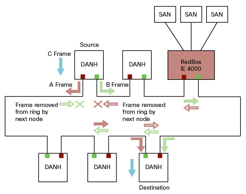
In HSR-SAN mode, the RedBox inserts the HSR tag on behalf of the host and forwards the ring traffic, except for frames sent by the node itself, duplicate frames, and frames for which the node is the unique destination. In this mode, packets are handled as follows:
-
A source DANH sends a frame passed from its upper layers ("C" frame), prefixes it with an HSR tag to identify frame duplicates, and sends the frame over each port ("A" frame and "B" frame).
-
A destination DANH receives two identical frames from each port within a certain interval. The destination DANH removes the HSR tag of the first frame before passing it to its upper layers and discards any duplicate.
-
Each node in the HSR ring forwards frames received from one port to the other port of the HSR pair. A node will not forward frames received on one port to the other under the following conditions:
-
The received frame returns to the originating node in the ring.
-
The frame is a unicast frame with a destination MAC address of a node upstream of the receiving node.
-
The node had already sent the same frame in the same direction. This rule prevents a frame from spinning in the ring in an infinite loop.
-
HSR-SAN Interfaces
HSR-SAN mode is supported on the following interfaces:
-
IE4000 - GigabitEthernet 1/1-4
-
IE4010 - GigabitEthernet 1/25-28
-
IE5000 - GigabitEthernet 1/17-20
See Guidelines and Limitations for port assignments.
HSR-PRP (Dual RedBox Mode)
HSR-PRP mode, also called Dual RedBox mode, is used to bridge HSR and PRP networks. Dual RedBox mode is supported on the IE 4000 only.
In this mode, two different RedBoxes connect to LAN A and LAN B of the PRP network. Two ports connect to the HSR ring and one port connects to one of the two PRP LANs. The traffic on the upstream interlink port connecting the RedBox to the PRP network is PRP-tagged. In HSR-PRP mode, the RedBox extracts data from the PRP frame and generates the HSR frame using this data, and performs the reverse in the opposite direction. To avoid loops and use network bandwidth effectively, the RedBox does not transmit frames already transmitted in same direction (see Loop Avoidance).
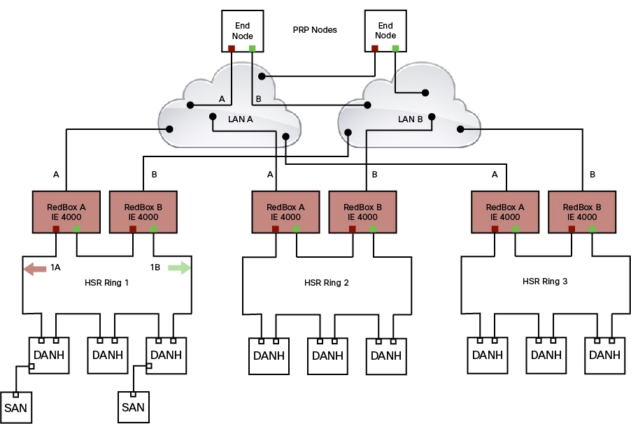
The following figure shows an HSR ring connected to a PRP network through two RedBoxes, one for each LAN. In this example, the source frame originates in the PRP network. RedBoxes are configured to support PRP traffic on the interlink ports and HSR traffic on the ring ports.
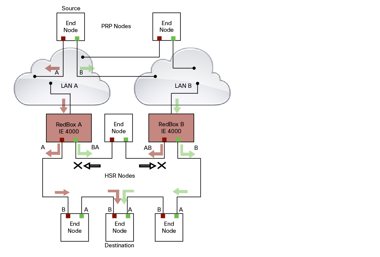
The sequence number from the PRP RCT is reused for the HSR tag and vice versa to allow frame identification from one redundancy network to the other and to identify the pairs and duplicates on either network. In the figure above, RedBox A and RedBox B send the same frame (A and AB and B and BA, respectively), but a RedBox does not transmit a frame that it already received.
Every DANH device generates its own sequence number, which is incremented for each outgoing frame. When a packet is switched from HSR to PRP or PRP to HSR, the sequence number is taken from the incoming packet so the same sequence number is used. Any node, whether it is an intermediate or final destination in the HSR or PRP network, uses the source MAC address and sequence number as the key for duplicate packet detection. Because the source address is expected to be unique for each node, there are no overlapping sequence numbers between different nodes.
Multicast frames or unicast frames without a receiver in the ring (arrows with the black outline in the figure) are removed by the RedBox that inserted them into the ring, if they originated from outside the ring. For this purpose, the frames carry a LAN identifier that is also the RedBox identifier.
The following figure shows an HSR ring coupled to a PRP network, where the source frame originates in the HSR ring.
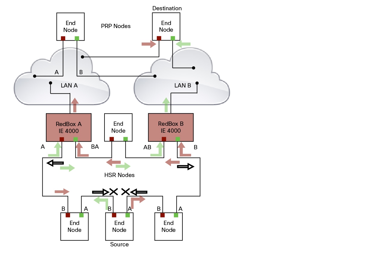
To prevent frames from being reinjected into the PRP network through the other RedBox, each HSR frame carries the 4-bit PathId, which identifies the PRP network from which the frame came originally. RedBoxes are configured and identified by the PathId of the PRP LAN to which they are attached.
Different PathIds can be used to bridge more than one PRP network to an HSR ring. Likewise, more than one HSR ring can be bridged to a PRP network.
HSR-PRP Interfaces
In HSR-PRP Dual RedBox mode (IE 4000 only), the device basically functions as a three-port device. All the other interfaces apart from these three interfaces are shut down by the software. These three interfaces are predefined:
-
Gi1/1, Gi1/3 and Gi1/4 for Redbox A
-
Gi1/2, Gi1/3 and Gi1/4 for Redbox B
The interface roles are predefined as well:
-
Gi1/3 and Gi1/4 are always used as HSR ring ports.
-
Gi1/1 is the interlink port for PRP Lan A.
-
Gi1/2 is the interlink port for PRP Lan B.
Connecting Multiple PRP Networks to an HSR Ring
A maximum of six PRP networks, identified by the PathId, can be connected to the same HSR ring. The 4-bit PathId consists of the following:
-
The 3-bit NetId (1 to 6), which identifies a PRP network and the two RedBoxes that connect the PRP network to an HSR ring.
-
The 1-bit LanId (LAN A = 0 and LAN B = 1)
NetId values are as follows:
-
0 for regular HSR frames
-
1 to 6 for frames originating from a PRP network
-
7 is reserved
The following table lists the combinations of NetIds and LanIds for Redbox-A and Redbox-B.
|
PathId |
||
|---|---|---|
|
NetId |
LanId |
|
|
RedBox-A |
RedBox-B |
|
|
001 |
0 |
1 |
|
010 |
0 |
1 |
|
011 |
0 |
1 |
|
100 |
0 |
1 |
|
101 |
0 |
1 |
|
110 |
0 |
1 |
|
000 |
Used for Local HSR Ring |
|
|
111 |
Reserved |
|
The following figure shows an example of an HSR ring connected to two PRP networks.
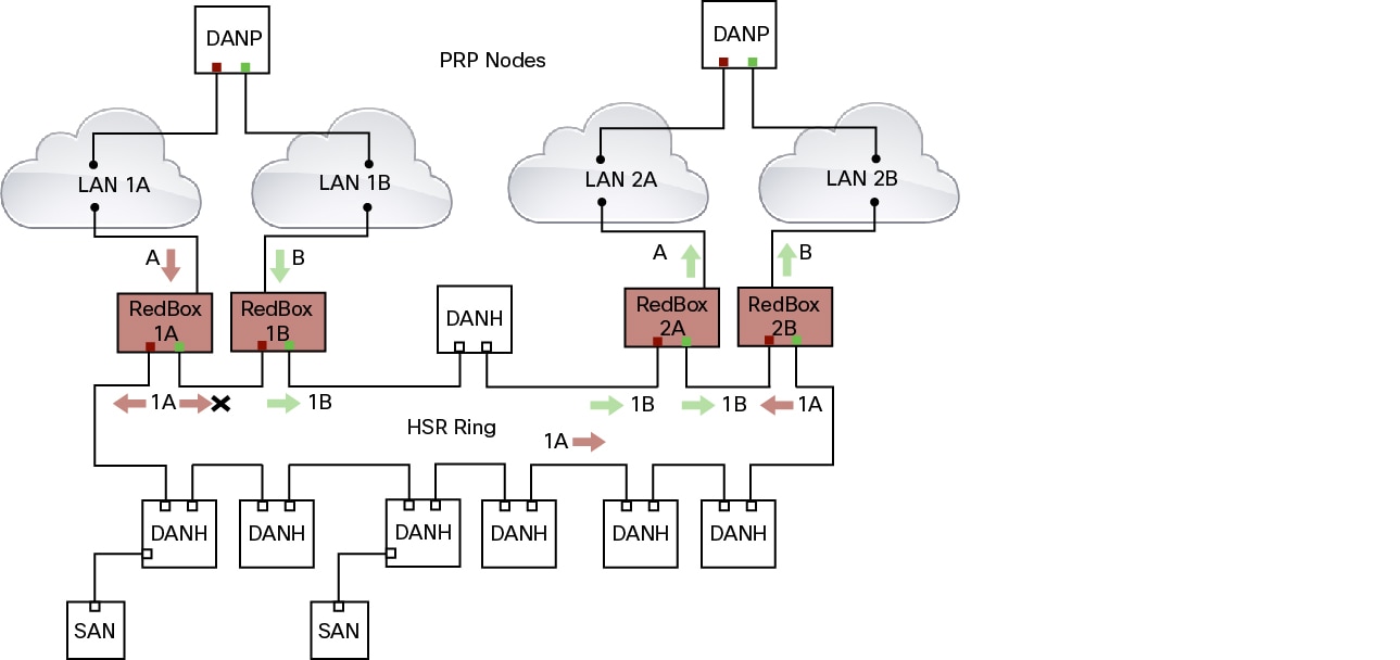
To prevent reinjection of frames coming from one PRP network into another PRP network or from the other LAN of the same PRP network, a RedBox only forwards frames that do not carry its own PathId from the HSR ring.
When a PRP frame from LAN A or from LAN B of a PRP network with a given NetId is inserted to the HSR ring, a RedBox inserts its own NetId and the LanId “A” or ”B” into the PathId of the HSR tag.
When forwarding a frame from the HSR ring to a PRP network, the RedBox inserts the LanId “A” or ”B” into the RCT.
Connecting Multiple HSR Rings to a PRP Network
A PRP network can be connected to any number of HSR rings, but these rings cannot be connected to each other because this would create loops. The following figure shows an example of three HSR rings connected to one PRP LAN.
HSR-HSR (QuadBox Mode)
The IE 4000 can operate as an HSR-HSR QuadBox. A QuadBox, or quadruple port device, connects two HSR rings to each other. On the IE 4000, the first two ports (Gi1/1 and Gi1/2) support HSR ring 1 and the next two ports (Gi1/3 and Gi1/4) support HSR ring 2. All other ports apart from these four ports are shut down and any feature running on any of these ports is not functional. This implementation ensures that the other ports that are not part of the 4-port QuadBox do not interfere with QuadBox operation.
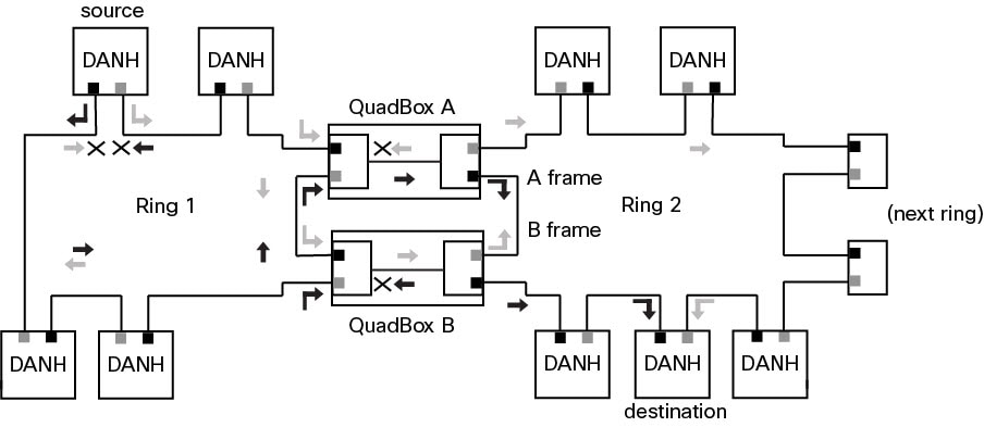
Each QuadBox creates a duplicate frame. More than one QuadBox in the topology can result in multiple copies of the same frame to be generated. However, only one copy is sent on each side of the ring, ensuring that eventually only two copies of a frame are sent on each ring. All subsequent duplicate frames received are dropped by the QuadBox. The following diagram illustrates HSR QuadBox packet flow.
To segregate traffic between the two rings, you can configure the QuadBox with VLAN and Multicast filters. This allows you to restrict the specified VLAN and Multicast groups from crossing the rings. VLAN filtering uses the VLAN allowed list to restrict VLANs. Multicast filtering matches packets with same MAC destination address (MACDA) and optional mask as configured in the filters. If there is a match, the packets are dropped.
CDP and LLDP for HSR
HSR supports the Cisco Discovery Protocol (CDP) and Link Layer Discovery Protocol (LLDP) are Layer 2 neighbor discovery protocols. Both CDP and LLDP can provide information about nodes directly connected to the device. They also provide additional information such as the local and remote interface and device names.
When CDP or LLDP is enabled, you can use the CDP or LLDP information to find the adjacent nodes on an HSR ring and their status. You can then use the neighbor information from each node to determine the complete HSR network topology and debug and locate ring faults.
CDP and LLDP are configured on physical interfaces only.
For more information, see Configuring an HSR Ring and Verifying Configuration.
PTP over HSR
Precision Time Protocol (PTP) is supported on the IE 4000, IE 4010, and IE 5000 for the PTP Power Profile.
Because the PTP 1588 standard does not currently account for clocks synchronized over redundant, simultaneously active paths, HSR must handle PTP packets differently that other packet types. To provide high availability for PTP through redundancy, the HSR duplicate/discard logic is not used for PTP packets.
The following example describes how PTP clock syncronization works in an HSR network. In this example, a VDAN/SAN is the PTP grandmaster clock. Dually attached devices receive PTP synchronization information over both their HSR ports. However, only one of the ports (referred to as SLAVE) is used to synchronize the local clock. The other HSR port (referred to as PASSIVE) continues to receive synchronization information, but is not used to synchronize the local clock. Suppose that RedBox 2 has its port-A as SLAVE and port-B as PASSIVE. When port-A goes down, the port-B port takes over as the SLAVE and is used to continue synchronizing the local clock on RedBox 2.
The PTP grandmaster in an HSR network can be a RedBox, a VDAN/SAN, or a DANH.
To use PTP over HSR, configure HSR and PTP separately. PTP over HSR works without any additional configuration. Note that in most cases, you do not need to perform any PTP configuration on the interfaces because PTP is enabled by default on all physical ethernet interfaces.
Supported PTP Profiles and Modes
PTP over HSR is supported only for the for the PTP Power Profile. For unsupported PTP profiles, PTP traffic flows over HSR port-A only.
The following table shows the HSR support for PTP profiles, clock modes and RedBox types.
|
PTP Profile |
Clock Mode |
Supported? |
HSR Redbox Type as per IEC 62439-3 |
|---|---|---|---|
|
Power Profile |
BC |
Yes |
HSR RedBox as doubly attached BC (DABC) with P2P |
|
P2P TC |
Yes |
HSR RedBox as doubly attached TC (DATC) with P2P |
|
|
Default Profile |
BC |
No |
Not applicable |
|
E2E TC |
No |
Not applicable |
|
|
802.1AS Profile |
Not applicable |
No |
Not applicable |
HSR RedBox as Doubly Attached BC (DABC) with P2P
This section describes the operation of PTP over HSR using an example where RedBox M and RedBox S are configured to run in Power Profile as Boundary Clocks that use the Peer-to-Peer delay measurement mechanism.
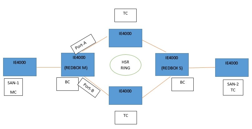
Assume for this example that SAN-1 is the GM. All the clocks are configured to run Peer-to-Peer Delay measurement and the peer delay is regularly calculated and maintained on every link shown in the figure. The BMCA on RedBox M determines ports A and B to be MASTER. The PTP protocol running on RedBox M treats both ports A and B individually as MASTER ports and sends out Sync and Follow_Up messages individually on both the ports.
On RedBox S, the regular BMCA operation determines port A to be SLAVE and port B to be PASSIVE. However, with the knowledge that ports A and B are part of the same HSR ring, port B is forced into PASSIVE_SLAVE state.
Port A works as a regular SLAVE port. It uses the Sync and Follow_Up messages along with their correction field to calculate the delay and offset from Master and synchronize the local clock. (Unlike an E2E BC, it does not need to generate Delay_Req messages since all the link delays and residence times along the PTP path are accumulated in the correction field of the Follow_Up messages.)
Port B, which is in PASSIVE_SLAVE state operates as follows: Just like port A, it maintains the delay and offset from master, but does not perform any operation on the local clock. Having all the synchronization information available enables it to seamlessly take over as the new SLAVE in case port A loses communication with the GM. Note that on IE switch platforms we currently do not support PTP profile conversion. For example, if RedBox S in the figure above were an IE switch, it would not support the Delay_Req/Delay_Resp message exchange. It would only support the Peer-to-Peer delay measurement mechanism using PDelay messages.
HSR RedBox as Doubly Attached TC (DATC) with P2P
This section describes the operation of PTP over HSR using an example where RedBox M and RedBox S are configured to run in Power Profile as Transparent Clocks.
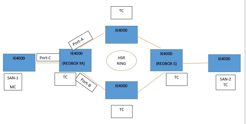
Assume for this example that SAN-1 is the GM. All the clocks are configured to run Peer-to-Peer Delay measurement and the peer delay is regularly calculated and maintained on every link shown in the figure. RedBox M and RedBox S run BMCA even though it is not mandatory for a P2P TC to run BMCA. On RedBox M, the BMCA determines ports A and B to be MASTER. RedBox M forwards all Sync and Follow_Up messages received on port C out of ports A and B.
On RedBox S, port A is determined to be SLAVE and port B to be PASSIVE_SLAVE as described earlier.
Port A operates as follows: It uses the Sync and Follow_Up messages along with their correction field to calculate the delay and offset from master and synchronize the local clock. (Unlike a E2E BC, it does not need to generate Delay_Req messages since all the link delays and residence times along the PTP path are accumulated in the correction field of the Follow_Up messages.) It also forwards the Sync and Follow_Up messages out of port C.
Port B operates as follows: Just like port A, it maintains the delay and offset from master, but does not perform any operation on the local clock. Having all the synchronization information available enables it to seamlessly take over as the new SLAVE in case port A loses communication with the GM. Post-processing, it drops the Sync/Follow_Up messages since the copy of Sync/Follow_Up that arrives on port A is forwarded out of port C.
HSR Alarms
An HSR ring can generate the following two alarms:
-
Partial Ring Fault: This fault is generated by an HSR RedBox when one of its physical ring ports/links is down. Because the packets can be sent using the redundant path, this is considered as a partial fault. However, this fault still requires user intervention to restore the ring. This is a minor fault and cannot be associated with an external hardware alarm relay.
-
Full Ring Fault: This fault is generated by an HSR RedBox when both of its physical ring ports/links are down. This is a catastrophic failure and needs immediate attention. This is a major fault and can be associated with an external hardware alarm relay.
When an event that raises an alarm is generated, it can be associated with one or more of the following actions to notify the user:
-
Syslog: A syslog is generated when the Alarm is raised/cleared.
-
SNMP Notification: SNMP notification is sent when the alarm is raised/cleared.
-
Relay output: External relay contacts can be asserted/de-asserted in response to the alarm. Relays are activated by major faults only.
See Enabling HSR Alarms for steps to configure HSR alarms.
The following table lists the HSR events and their representations.
|
Event Number |
Event Description |
System Log (Level) |
Alert/Alarm Log |
Alarm LED and Output relay |
|---|---|---|---|---|
|
1 |
Ring goes from UP to DOWN state. |
2 |
2 |
Major Alarm/Assert |
|
2 |
Ring goes from DOWN to UP state. |
6 |
6 |
De-assert |
|
3 |
One ring port goes DOWN, the other ring port and the ring itself is UP. |
3 |
3 |
|
|
4 |
Both ring ports are UP again. |
6 |
6 |
You can view currently active alarms using the show facility alarm status command. The following example shows alarm status for minor and major HSR alarms:
Switch#show facility-alarm status
Source          Severity    Description                      Relay   Time
Switch            MINOR    34 HSR ring is partially down        MAJ    Oct 24 2017 10:16:10
-------
Switch# show facility-alarm status
Source          Severity    Description                   Relay     Time
Switch            MAJOR    33 HSR ring is down               MAJ      Oct 24 2017 10:17:07
The following examples show the syslog entries that are generated for each HSR alarm event assertion and clear event (if configured):
-
Syslog generated on occurrence of Partial fault:
Oct 24 11:07:13.952 IST: %HSR_ALARM-3-HSR_PARTIALFAULT: The HSR ring in now in PARTIAL FAULT state -
Syslog generated when the Partial fault is cleared:
Oct 24 11:07:38.032 IST: %HSR_ALARM-3-HSR_PARTIALFAULT: The HSR ring in now in PARTIAL FAULT state - event cleared -
Syslog generated on occurrence of Full fault:
Oct 24 11:07:38.036 IST: %HSR_ALARM-2-HSR_RINGFAULT: The HSR ring in now in FAULT state -
Syslog generated when the Full fault is cleared:
Oct 24 11:08:19.082 IST: %HSR_ALARM-2-HSR_RINGFAULT: The HSR ring in now in FAULT state - event cleared
HSR Uplink Redundancy Enhancement
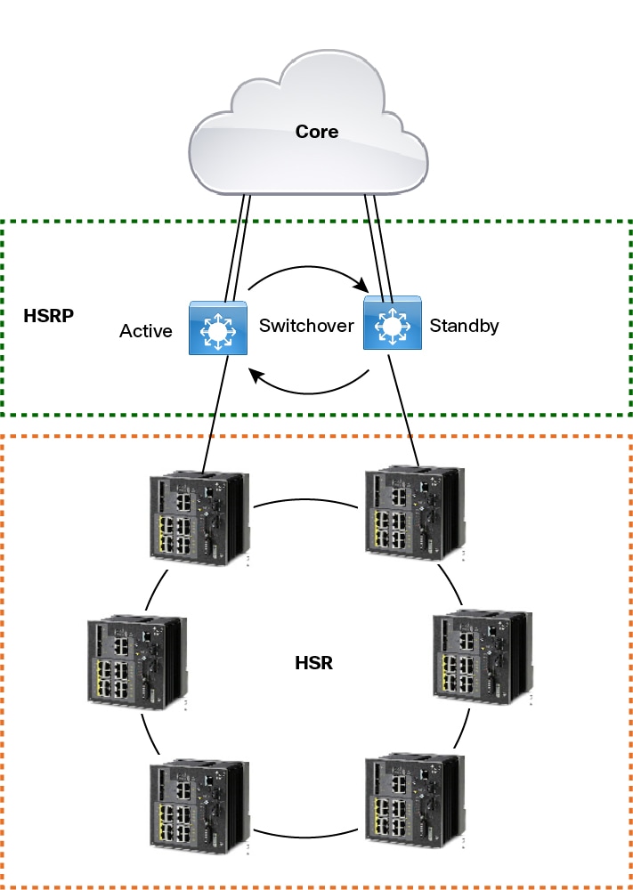
The HSR Uplink Redundancy Enhancement feature allows for flexible designs that enable two separate interfaces to connect upstream from the HSR ring through two separate HSR RedBoxes. This ensures there is no single point of failure exiting the HSR ring. Examples of protocols that can leverage this feature to improve high availability include HSRP, VRRP and REP. Prior to this enhancement, if these protocols were utilized on redundant uplinks, undesirable results could occur, such as next-hop split-brain conditions or slow REP failover times.
The following diagram shows an example network with HSR and HSRP that allows uplink next-hop gateway redundancy out of the HSR ring.
Guidelines and Limitations
-
HSR-SAN (Single RedBox mode) is supported on the IE 4000, IE 4010, and IE 5000.
-
HSR-PRP (Dual RedBox mode) and HSR-HSR (Quadbox mode) are supported on the IE 4000 only.
-
A maximum of 4 ports support HSR/PRP. Using these 4 ports, you can create one of the following configurations:
-
HSR rings: Maximum of two
-
PRP channel: Maximum of two
-
One HSR ring and one PRP channel
-
-
Physical interfaces are predefined for the rings and ports in HSR-SAN, HSR-PRP, and HSR-HSR modes and cannot be changed. Port assigments for each HSR mode are shown in the following table:
SKU
HSR Mode
Port Type
Interface Number
IE4000
HSR-SAN
Ring 1, Port 1
GE 1/1
Ring 1, Port 2
GE 1/2
Ring 2, Port-A
GE 1/3
Ring 2, Port-B
GE 1/4
IE4010
HSR-SAN
Ring 1, Port 1
GE 1/25
Ring 1, Port 2
GE 1/26
Ring 2, Port-A
GE 1/27
Ring 2, Port-B
GE 1/28
IE5000
HSR-SAN
Ring 1, Port 1
GE 1/17
Ring 1, Port 2
GE 1/18
Ring 2, Port-A
GE 1/19
Ring 2, Port-B
GE 1/20
IE4000
HSR-PRP
PRP-LAN-A (RedBox A)
-
PRP channel interface—Gi1/1 (Port 3)
-
HSR ring interfaces—Gi1/3 (Port 1), Gi1/4 (Port 2)
Gi 1/2 is unused.
PRP-LAN-B (RedBox B)
-
PRP channel interface—Gi1/2 (Port 3)
-
HSR ring interfaces—Gi1/3 (Port 1), Gi1/4 (Port 2)
Gi 1/1 is unused.
HSR-HSR
HSR Ring 1
HSR ring interfaces—Gi1/1 and Gi1/2
HSR Ring 2
HSR ring interfaces—Gi1/3 and Gi1/4
-
-
The recommended maximum number of nodes in the node table is 512. Nodes are all the DANH and VDAN devices that can be connected to the ring at same time. This number is not an absolute limit, but higher numbers of entries may increase the number of duplicate packets received by the end devices.
-
HSR ring ports can only be configured in L2 mode.
-
Ring 1 and Ring 2 can both be configured in HSR-SAN mode. On the IE 4000 in HSR-PRP Dual Redbox mode, three ports participate in the HSR-PRP network; therefore only Ring 2 can be configured.
-
The following protocols and features are are mutually exclusive with HSR on the same port:
-
PRP
-
EtherChannels
-
Link Aggregation Control Protocol (LACP)
-
Port Aggregation Protocol (PAgP)
-
Resilient Ethernet Protocol (REP)
-
-
MACsec, HSR, and PRP are not allowed together.
-
HSR/PRP supports an MTU size of up to 1998 bytes of Ethernet payload.
-
STP is not supported on the HSR ring. By default, all modes of Spanning Tree Protocol (STP) will be disabled on the ring ports.
-
Switched Port Analyzer (SPAN) and Remote SPAN (RSPAN) is not supported on HSR. That is, SPAN and RSPAN should not be used to monitor the traffic on an HSR ring. In addition, traffic that has been monitored using RSPAN should not be transferred over an HSR ring.
-
Once a port is part of a ring, the media-type, speed, and duplex settings of the port cannot be changed. It is recommended to apply those settings before configuring ring membership.
-
Once a port is part of ring, the port cannot be shut down.
For example, if G1/3 and G1/4 are part of HSR ring 2 and you try to shut down G1/3 or G1/4, the operation will not be permitted:
Switch(config)# interface range g1/3 Switch(config-if-range)#shutdown %Interface GigabitEthernet1/3 is configured in a HSR ring shutdown not permitted! Switch(config-if-range)# -
VLAN configuration such as trunk and access mode must be the same on both the ports participating in the ring. For example, if G1/4 and G1/3 of HSR ring 2 are in trunk mode and you attempt to change the mode of one port to access, the ports in the ring will not be bundled:
Switch(config)# interface range g1/3 Switch(config-if-range)# switchport mode access Jul 27 22:00:27.809 IST: %EC-5-CANNOT_BUNDLE2: Gi1/3 is not compatible with Gi1/4 and will be suspended (trunk mode of Gi1/3 is access, Gi1/4 is dynamic) -
After an interface is added in the HSR ring, only the primary interface counters are updated. You should not need to configure and check the status of individual physical interfaces after they are added to the HSR ring.
-
As soon as you configure an HSR ring on two ports of a switch, MAC flaps will be observed on other switches where HSR configuration is yet to be applied. We recommend that you shut down the ports before configuring the ring on all switches and then reenable them one by one as shown below. For example, if there are four switches in the ring, disable the ports on all switches before enabling the ring:
Switch(config)# interface range g1/1-2
Switch(config-if-range)# shutdown
Switch(config-if-range)# hsr-ring 1
Creating a HSR-ring interface 1
Switch(config-if-range)# end
After all four switches are configured with the ring, reenable the member ports one by one:
Switch# conf t
Enter configuration commands, one per line. End with CNTL/Z.
Switch(config)# interface range g1/1-2
Switch(config-if-range)# no shutdown
Switch(config-if-range)# end
Switch#
This prevents interim MAC flapping during HSR ring configuration in member switches.
HSR-PRP Dual RedBox mode
-
Because three ports participate in the HSR-PRP network, only HSR ring 2 can be configured in HSR-PRP mode.
-
Interface assignment is fixed and cannot be changed. Refer to the table above for the assigned interfaces in HSR-PRP mode.
-
When HSR-PRP Dual RedBox mode is configured and enabled, all other ports apart from the 3 HSR-PRP ports are shut down and any feature running on any of these ports will not be functional. You will be warned about this mode change.
-
When HSR-PRP RedBox is active, all other interfaces that are not part of the RedBox remain in the shutdown state and are unusable as long as the RedBox mode is active.
Management of the switch through Device Manger is still possible with an in-band SVI interface reachable over the HSR Ring or PRP network. However, there will be loss of connection for a period of time when RedBox mode is enabled or disabled and the device reconfigures itself. Therefore, we highly recommend that you use a console connection when switching into or out of HSR-PRP mode.
-
When HSR-PRP mode is disabled, all physical interfaces will return to their default configuration (that is, configuration on non-RedBox physical ports will be lost).
-
In HSR-PRP mode, by design PRP/HSR channel 1 (gi1/1-2) operates in "PRP/HSR disabled" mode. Frames coming into these two ports are passed through to the hardware for switching to the HSR-PRP enabled channel 2. Because channel 1 is not used for PRP or HSR in HSR-PRP mode, the show prp channel 1 detail command displays "Protocol = Disabled" even though the Port state displays "Inuse".
-
In HSR-PRP Dual Redbox mode, during reload of the HSR-PRP switch when the traffic is in progress, MAC flaps occur once per source MAC address in the switch that is reloaded and also on the PRP device that is transmitting the traffifc. Therefore, if there are 512 different source MAC addresses, then MAC flaps are observed 512 times (once per source MAC address). Also some duplicate packets are seen after this event.
PTP over HSR
-
PTP over HSR is supported only for the PTP Power profile.
-
PTP over HSR does not support Hybrid clock mode. Only Boundary clock and transparent clock modes are supported.
-
We recommend that you have identical PTP configuration on the interfaces that are part of the same HSR ring to allow for seamless transitions between PASSIVE_SLAVE and SLAVE states.
HSR-HSR QuadBox Mode
-
Interface assignment is fixed and cannot be changed. Refer to the table above for the assigned interfaces in HSR-HSR mode.
-
When HSR-HSR QuadBox mode is configured and enabled, all other ports apart from the 4 HSR-HSR ports are shut down and any feature running on any of these ports will not be functional. You will be warned about this mode change.
-
When HSR-HSR QuadBox is active, all other interfaces that are not part of the RedBox remain in the shutdown state and are unusable as long as the RedBox mode is active.
Management of the switch through Device Manger is still possible with an in-band SVI interface reachable over the HSR Ring. However, there will be loss of connection for a period of time when QuadBox mode is enabled or disabled and the device reconfigures itself. Therefore, we highly recommend that you use a console connection when switching into or out of HSR-HSR mode.
-
When HSR-HSR mode is disabled, all physical interfaces will return to their default configuration (that is, configuration on non-QuadBox physical ports will be lost).
-
HSR sends two packets from source to destination. The destination is guaranteed to receive one packet in a fault condition and both packets under normal conditions. On QuadBox devices, the redundant packet may arrive on different rings, which may cause MAC address flapping to be reported under normal conditions. To avoid this, MAC address learning is disabled. Because all other ports are shut down, there is no unnecessary flooding of packets.
-
When the topology has more than one QuadBox, the VLAN and multicast filter configuration must match on all the QuadBoxes.
-
Switchport mode access is restricted in HSR-HSR mode.
-
MTU size is fixed to 2020 in HSR-HSR mode and cannot be altered.
-
MAC address table learning for VLAN 1-4094 is disabled and cannot be altered.
-
PTP is by default disabled (due to no FPGA support) but is not restricted to use.
-
show and clear commands for Node and VDAN table, HSR ring proxyNodeTableForgetTime, HSR ring nodeforgetTime, and creating independent HSR ring interfaces (that is, not part of HSR-HSR mode) are restricted in HSR-HSR profile.
-
Multicast filters are designed to drop only Multicast MACDA. The filter set as Unicast MAC addresses will not result in any packet drop.
Default Settings
|
Parameter |
Description |
Range |
Default Value |
|---|---|---|---|
|
RedboxMacaddress |
The RedBox MAC address in the supervision frames. |
48-bit RedBox MAC address |
The interface HSR ring MAC address |
|
nodeForgetTime |
Time to clear an inactive entry from the node table. |
0-65535 |
6000 ms |
|
nodeRebootInterval |
Time after which the RedBox must start sending supervision frames after bootup. |
0-65535 |
500 ms |
|
entryForgetTime |
Time for clearing the inactive entry from duplicate discard table. |
0-65535 |
400 ms |
|
proxyNodeForgetTime |
Time to clear an inactive entry from the proxy node table or vdan table. |
0-65535 |
6000 ms |
|
supervisionFrameCosOption |
COS value to be set in the VLAN tag of the Supervision frame (valid only if Supervision Frame VLAN Tag option is Enabled). |
0-7 |
0 |
|
supervisionFrameCfiOption |
CFI value to be set in the VLAN tag of the Supervision frame (valid only if Supervision Frame VLAN Tag option is Enabled). |
0 |
|
|
supervisionFrameVlanTagOption |
Enables the VLAN tagging of supervision frames. |
Enabled or Disabled |
Disabled |
|
SupervisionFrameMacDa |
The last bytes of the destination MAC address of supervision frames (01:15:4E:00:01:00). The last 00 will be replaced by the value depending on this parameter. |
1-255 MAC DA last eight bits option value |
0x00 |
|
SupervisionFrameVlanId |
The VLAN tag of supervision frame (valid only if Supervision Frame VLAN Tag option is Enabled). |
0-4095 |
0 |
|
supervisionFrameTime |
Time interval between supervision frames. |
0-65535 |
3 ms |
|
LifeCheckInterval |
Life check interval value for supervision frames. |
0-65535 |
2000 ms |
Configuring an HSR Ring
Follow these steps to configure an HSR ring:
Before you begin
-
(IE 4000 only) Before configuring HSR, if the switch is in the default feature mode (MRP), you must switch to the HSR feature mode as shown in step 1 below. This step requires a reload.
For more information about Feature Mode, see Feature Mode for IE 4000 Switches.
-
Ensure that the member interfaces of a HSR ring are not participating in any redundancy protocols such as FlexLinks, EtherChannel, REP, and so on before configuring a HSR ring.
Procedure
| Step 1 |
(IE 4000 only) Activate HSR feature mode: For the change to take effect, the switch must be reloaded. Confirm the reload when prompted and wait for the switch to reload and boot. |
| Step 2 |
(IE 4000 only) Verify that the HSR feature is activated: |
| Step 3 |
Enter global configuration mode: |
| Step 4 |
(Optional) Globally enable CDP to provide information about HSR ring nodes: |
| Step 5 |
(Optional) Globally enable LLDP to provide information about HSR ring nodes: |
| Step 6 |
Enter interface configuration mode and disable PTP on the ports to be assigned to the HSR ring: |
| Step 7 |
(Optional) Enable CDP on the ports to be assigned to the HSR ring: |
| Step 8 |
(Optional) Enable LLDP on the ports to be assigned to the HSR ring: |
| Step 9 |
Shut down the ports before configuring the HSR ring: |
| Step 10 |
Create the HSR ring interface and assign the ports to the HSR ring: |
| Step 11 |
(Optional) Configure HSR ring optional parameters. See Default Settings for the parameter descriptions, ranges and default values. |
| Step 12 |
Turn on the HSR interface: |
Example
Example
Switch# license right-to-use activate hsr
For the license activation changes to take effect, the Switch must be reloaded.
Switch# reload
Proceed with reload? [confirm]
Switch# show version | inc Feature
Feature Mode                    : 0x25 Enabled: HSR (Disabled: MRP TSN)
Switch# conf t
Enter configuration commands, one per line. End with CNTL/Z.
Switch(config)# interface range gigabitEthernet 1/1-2
Switch(config-if-range)# no ptp enable
Switch(config-if-range)# shutdown
Switch(config-if-range)# hsr-ring 1
Switch(config-if-range)# hsr-ring 1 supervisionFrameLifeCheckInterval 10000
Switch(config-if-range)# no shutdown
Switch(config-if-range)# end
Configuring HSR-PRP
Follow these steps to configure HSR-PRP mode on the switch. Enabling HSR-PRP mode creates an HSR ring and a PRP channel.
Before you begin
-
Enabling HSR-PRP mode will disable all ports other than two HSR ports and one PRP port and all port settings for these disabled ports will return to default values. Similarly, disabling HSR-PRP mode returns these ports from “shut” or disabled mode to “no shut” mode. A warning message is displayed to notify you that interface configurations will be removed. Before enabling or disabling HSR-PRP mode, check any cables connected to the switch and verify the ports' status.
-
HSR-PRP Redbox mode uses ports Gi1/3 and Gi1/4 as HSR ring 2 interfaces, and Gi1/1 (for Redbox A) or Gi1/2 (for Redbox B) as PRP channel 1 interfaces. These port assignments are fixed and cannot be changed. Therefore, HSR-PRP Dual Redbox mode is supported only on HSR ring 2.
SUMMARY STEPS
- Activate HSR feature mode:
- Verify that the HSR feature is activated:
- Enter global configuration mode:
- Enable HSR-PRP mode and select LAN A or LAN B and the PRP Net ID:
- Enter yes to confirm enabling HSR-PRP mode.
- To configure the maximum transmission unit (MTU) size for sending 1518 byte traffic through the HSR-PRP RedBox, enter the following commands:
- To configure the MTU size for sending 1998 byte (mini jumbo) traffic through the HSR-PRP RedBox, enter the following commands:
- Modify HSR ring parameters as required. See Configuring an HSR Ring.
DETAILED STEPS
| Step 1 |
Activate HSR feature mode: For the change to take effect, the switch must be reloaded. Confirm the reload when prompted and wait for the switch to reload and boot. |
||
| Step 2 |
Verify that the HSR feature is activated: |
||
| Step 3 |
Enter global configuration mode: |
||
| Step 4 |
Enable HSR-PRP mode and select LAN A or LAN B and the PRP Net ID:
The system displays a message to warn you that enabling this mode causes Ethernet ports that are not part of the 3-port RedBox to no longer be operational. |
||
| Step 5 |
Enter yes to confirm enabling HSR-PRP mode. To disable HSR-PRP Redbox mode, use the command no hsr-prp-mode enable . |
||
| Step 6 |
To configure the maximum transmission unit (MTU) size for sending 1518 byte traffic through the HSR-PRP RedBox, enter the following commands: |
||
| Step 7 |
To configure the MTU size for sending 1998 byte (mini jumbo) traffic through the HSR-PRP RedBox, enter the following commands: |
||
| Step 8 |
Modify HSR ring parameters as required. See Configuring an HSR Ring. |
Configuring HSR-HSR
Follow these steps to configure HSR-HSR mode on the switch and configure VLAN and multicast filters. Enabling HSR-HSR mode creates two HSR rings. You can configure VLAN and multicast filters to control what traffic is allowed on the HSR rings.
Note |
If there is more than one QuadBox in the topology, make sure that the configured VLAN allowed list and multicast filters are the same on both QuadBoxes. |
Before you begin
-
See Guidelines and Limitations for HSR-HSR QuadBox Mode.
-
Activating HSR-HSR mode will disable all ports other than the four HSR-HSR ports and all port settings for these disabled ports will return to default values. A warning message is displayed to notify you that interface configurations will be removed. Before enabling or disabling HSR-HSR mode, check any cables connected to the switch and verify the ports' status.
-
Ensure that both QuadBox rings and connected ports are in same native VLAN.
Procedure
| Step 1 |
Activate the license for HSR-HSR: For the activation to take effect, the switch must be reloaded. Confirm the reload when prompted and wait for the switch to reload and boot. After reload, the system creates HSR ring interfaces 1 and 2 and activates HSR-HSR mode automatically. You cannot disable HSR-HSR mode unless you change the feature mode profile. |
| Step 2 |
(Optional) To configure multicast filtering for the QuadBox, enter the following command:
|
| Step 3 |
(Optional) To configure VLAN filtering for HSR ring interface 1 or HSR ring interface 2, enter interface configuration mode for the interface and enter the following command: where <1-4096> is the VLAN or VLAN range to allow on the HSR ring. All other VLANs are dropped. |
Example
Example
Switch(config)#license right-to-use activate hsr-hsr
For the license activation changes to take effect, the Switch must be reloaded.
After reload, HSR-HSR mode is enabled automatically
PLEASE READ THE FOLLOWING INFORMATION ABOUT THE HSR-HSR MODE:
Ethernet ports that are not part of the feature will
no longer be operational.

When operating in this mode note the following:
1. When this mode is configured and enabled, all other ports apart
from the mode ports, will be shut down. Any feature running on these
Ethernet ports will no longer function.
2. The only means to manage the Switch will be available through the Serial Console.
3. IP management of the Switch will be restored once "inband access via HTTP/HTTPS"
is configured and Device Manager will be not be accessible until inband
IP management is operational.
4. Make sure Native VLAN is same on both the Quadboxes.
5. Make sure Vlan allowed list configuration and Multicast
filters configured are same on both quadboxes
6. The CLI switchport mode access will be disabled
when quadbox is enabled
7. Switchport access mode will be disabled when HSR-HSR is configured.

ACCEPT? (yes/[no]): yes
Creating a HSR-ring interface 1

Creating a HSR-ring interface 2

Interface FastEthernet1/5 set to default configuration
Interface FastEthernet1/6 set to default configuration
Interface FastEthernet1/7 set to default configuration
Interface FastEthernet1/8 set to default configuration
Interface FastEthernet1/9 set to default configuration
Interface FastEthernet1/10 set to default configuration
Interface FastEthernet1/11 set to default configuration
Interface FastEthernet1/12 set to default configuration

  Activated HSR-HSR mode

Switch#conf t
Enter configuration commands, one per line.  End with CNTL/Z.
Switch(config)#hsr-ring 1 multicast_filter_deny_group 1 0000.0100.0a00 ffff.ffff.ffff

Switch(config)#hsr-ring 2 multicast_filter_deny_group 5 0000.0100.0b00

Switch(config)#interface gi1/1 - 4
Switch(config-if-range)# switchport mode trunk allowed vlan 1-10

Switch(config-if-range)# end
What to do next
See Verifying Configuration for information about displaying HSR-HSR ring details, as well as the multicast and VLAN filter configuration and the number of packets dropped due to the filtering.
Enabling HSR Alarms
To enable alarms for HSR, follow these steps:
Before you begin
Alarms and actions can be enabled/disabled at the facility level only. You cannot enable only partial faults or full faults; either all alarms for given facility are enabled or all are disabled.
See HSR Alarms for details about HSR alarms.
SUMMARY STEPS
- Enter global configuration mode:
- Enable the HSR alarm facility:
- (Optional) Enable SNMP notification for HSR alarms:
- (Optional) Associate HSR alarms with the Major Relay:
- Exit global configuration mode:
DETAILED STEPS
| Step 1 |
Enter global configuration mode: |
| Step 2 |
Enable the HSR alarm facility: To disable HSR alarms, enter no alarm facility hsr enable . |
| Step 3 |
(Optional) Enable SNMP notification for HSR alarms: |
| Step 4 |
(Optional) Associate HSR alarms with the Major Relay: |
| Step 5 |
Exit global configuration mode: |
Clearing All Node Table and VDAN Table Dynamic Entries
To clear all dynamic entries in the node table, enter
clear hsr node-table
To clear all dynamic entries in the VDAN table, enter
clear hsr vdan-table
Verifying Configuration
|
Command |
Purpose |
||
|---|---|---|---|
|
show hsr ring {1 | 2 } [detail ] |
Displays configuration details for the specified HSR ring. |
||
|
show hsr ring {1 | 2 } multicast-filter |
(HSR-HSR mode only) Displays the list of MAC addresses that are configured to be dropped. |
||
|
show multicast-filter-drop-count |
(HSR-HSR mode only) Displays the number of frames dropped as a result of the configured multicast filtering. |
||
|
show hsr ring {1 | 2 } vlan-filter |
(HSR-HSR mode only) Displays the list of VLANs allowed for each ring. |
||
|
show vlan-filter-drop-count |
(HSR-HSR mode only) Displays the number of frames dropped as a result of the configured VLAN filtering. |
||
|
show hsr statistics {egressPacketStatistics | ingressPacketStatistics | nodeTableStatistics | pauseFrameStatistics } |
Displays statistics for HSR components.
|
||
|
show hsr node-table |
Displays HSR node table. |
||
|
show hsr vdan-table |
Displays HSR Virtual Doubly Attached Node (VDAN) table.
|
||
|
show cdp neighbors |
Displays CDP neighbor information for an HSR ring. |
||
|
show lldp neighbors |
Displays LLDP neighbor information for an HSR ring. |
||
|
show alarm settings | begin hsr |
Display HSR alarm configuration. |
Example - Displaying HSR Ring Details
The following example shows HSR ring details for HSR-HSR mode:
Switch#show hsr ring detail
                HSR-ring listing:
                --------------------

HSR-ring: HS1
------------
 Layer type = L2
 Operation Mode = mode-H
 Ports: 2       Maxports = 2
 Port state = hsr-ring is Inuse
 Protocol = Enabled  Redbox Mode = hsr-hsr
Ports in the ring:
  1) Port: Gi1/1
   Logical slot/port = 1/1      Port state = Inuse
        Protocol = Enabled
  2) Port: Gi1/2
   Logical slot/port = 1/2      Port state = Inuse
        Protocol = Enabled

Ring Parameters:
 Redbox MacAddr: 70db.984a.5040
 Node Forget Time: 60000 ms
 Node Reboot Interval: 500 ms
 Entry Forget Time: 400 ms
 Proxy Node Forget Time: 60000 ms
 Supervision Frame COS option: 0
 Supervision Frame CFI option: 0
 Supervision Frame VLAN Tag option: Disabled
 Supervision Frame MacDa: 0x00
 Supervision Frame VLAN id: 0
 Supervision Frame Time: 3 ms
 Life Check Interval: 1600 ms
 Pause Time: 25 ms
 fpgamode-DualUplinkEnhancement: Enabled

HSR-ring: HS2
------------
 Layer type = L2
 Operation Mode = mode-H
 Ports: 2       Maxports = 2
 Port state = hsr-ring is Inuse
 Protocol = Enabled  Redbox Mode = hsr-hsr
Ports in the ring:
  1) Port: Gi1/3
   Logical slot/port = 1/3      Port state = Inuse
        Protocol = Enabled
  2) Port: Gi1/4
   Logical slot/port = 1/4      Port state = Inuse
        Protocol = Enabled

Ring Parameters:
 Redbox MacAddr: 70db.984a.5040
 Node Forget Time: 60000 ms
 Node Reboot Interval: 500 ms
 Entry Forget Time: 400 ms
 Proxy Node Forget Time: 60000 ms
 Supervision Frame COS option: 0
 Supervision Frame CFI option: 0
 Supervision Frame VLAN Tag option: Disabled
 Supervision Frame MacDa: 0x00
 Supervision Frame VLAN id: 0
 Supervision Frame Time: 3 ms
 Life Check Interval: 1600 ms
 Pause Time: 25 ms
 fpgamode-DualUplinkEnhancement: Enabled
Switch#
Example - Displaying Multicast and VLAN Filtering Information (HSR-HSR Mode Only)
The following example shows how to display the multicast and VLAN filter configuration and the number of packets dropped due to the filtering:
Switch#show hsr ring multicast-filter
                HSR-ring listing:
                --------------------
HSR-ring: HS1
---------------

Filter No.  Address         Mask
=============================================
2           0000.0100.0a00 ffff.ffff.ffff


HSR-ring: HS2
---------------

Filter No.  Address         Mask
=============================================
5           0000.0100.0b00 0000.0000.0000
Switch#

Switch#show hsr ring allowed-vlan
                HSR-ring listing:
                --------------------

HSR-ring: HS1
---------------

Vlan allowed list
----------------------
0-4094

HSR-ring: HS2
---------------

Vlan allowed list
----------------------
0-4094


Switch#show hsr ring multicast-filter-drop
                HSR-ring listing:
                --------------------

HSR-ring: HS1
---------------

Multicast filter drop count: 0
HSR-ring: HS2
---------------

Multicast filter drop count: 0

Switch#show hsr ring allowed-vlan
                HSR-ring listing:
                --------------------

HSR-ring: HS1
---------------

Vlan allowed list
----------------------
0-4094

HSR-ring: HS2
---------------

Vlan allowed list
----------------------
0-4094

Switch#
Example - Displaying Neighbor Information
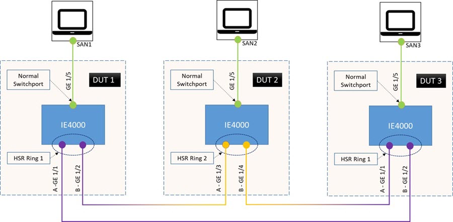
The following example shows how to display CDP neighbor information for an HSR ring. For this example, there are three switches with the topology shown in the following diagram. CDP is enabled on all three switches.
DUT 2#sh cdp neighbors
Capability Codes: R - Router, T - Trans Bridge, B - Source Route Bridge
                  S - Switch, H - Host, I - IGMP, r - Repeater, P - Phone,
                  D - Remote, C - CVTA, M - Two-port Mac Relay

Device ID        Local Intrfce     Holdtme    Capability  Platform  Port ID
DUT 1            Gig 1/3           160              S I   IE-4000-8 Gig 1/2
DUT 3            Fas 1/4           163              S I   IE-4000-8 Gig 1/1

Total cdp entries displayed : 2
The following example shows how to display LLDP neighbor information for an HSR ring. This example uses the same topology as shown in the figure above. LLDP is enabled on all three switches.
DUT 2#sh lldp neighbors
Capability codes:
    (R) Router, (B) Bridge, (T) Telephone, (C) DOCSIS Cable Device
    (W) WLAN Access Point, (P) Repeater, (S) Station, (O) Other

Device ID           Local Intf     Hold-time  Capability      Port ID
DUT 1               Gi1/3          120        B               port-002
DUT 3               Gi1/4          120        B               port-001

Total entries displayed: 2
Configuration Example
HSR-SAN
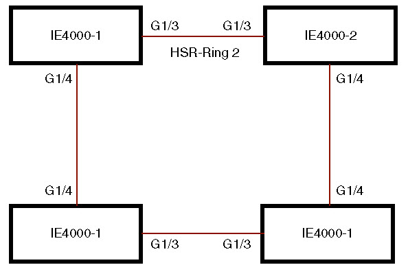
This example shows the configuration of an HSR ring (Ring 2) using G1/3 and G1/4 ports between four devices.
IE4000-1# conf t
Enter configuration commands, one per line.  End with CNTL/Z.
IE4000-1(config)# interface range g1/3-4
IE4000-1(config-if-range)# shutdown
IE4000-1(config-if-range)# hsr-ring 2
IE4000-1(config-if-range)# no shutdown
IE4000-1(config-if-range)# end
IE4000-1#
IE4000-2# conf t
Enter configuration commands, one per line.  End with CNTL/Z.
IE4000-2(config)# interface range g1/3-4
IE4000-2(config-if-range)# shutdown
IE4000-2(config-if-range)# hsr-ring 2
IE4000-2(config-if-range)# no shutdown
IE4000-2(config-if-range)# end
IE4000-2#
IE4000-3# conf t
Enter configuration commands, one per line.  End with CNTL/Z.
IE4000-3(config)# interface range g1/3-4
IE4000-3(config-if-range)# shutdown
IE4000-3(config-if-range)# hsr-ring 2
IE4000-3(config-if-range)# no shutdown
IE4000-3(config-if-range)# end
IE4000-3#
IE4000-4# conf t
Enter configuration commands, one per line.  End with CNTL/Z.
IE4000-4(config)# interface range g1/3-4
IE4000-4(config-if-range)# shutdown
IE4000-4(config-if-range)# hsr-ring 2
IE4000-4(config-if-range)# no shutdown
IE4000-4(config-if-range)# end
IE4000-4#
IE4000-1# sh hsr ring 2 detail
HSR-ring: HS2
------------
 Layer type = L2
 Operation Mode = mode-H
 Ports: 2       Maxports = 2
 Port state = hsr-ring is Inuse
 Protocol = Enabled  Redbox Mode = hsr-san
Ports in the ring:
  1) Port: Gi1/3
   Logical slot/port = 1/3      Port state = Inuse
        Protocol = Enabled
  2) Port: Gi1/4
   Logical slot/port = 1/4      Port state = Inuse
        Protocol = Enabled

Ring Parameters:
 Redbox MacAddr: f454.3365.8a84
 Node Forget Time: 60000 ms
 Node Reboot Interval: 500 ms
 Entry Forget Time: 400 ms
 Proxy Node Forget Time: 60000 ms
 Supervision Frame COS option: 0
 Supervision Frame CFI option: 0
 Supervision Frame VLAN Tag option: Disabled
 Supervision Frame MacDa: 0x00
 Supervision Frame VLAN id: 0
 Supervision Frame Time: 3 ms
 Life Check Interval: 2000 ms
 Pause Time: 25 ms

IE4000-2# show hsr ring 2 detail
HSR-ring: HS2
------------
 Layer type = L2
 Operation Mode = mode-H
 Ports: 2       Maxports = 2
 Port state = hsr-ring is Inuse
 Protocol = Enabled  Redbox Mode = hsr-san
Ports in the ring:
  1) Port: Gi1/3
   Logical slot/port = 1/3      Port state = Inuse
        Protocol = Enabled
  2) Port: Gi1/4
   Logical slot/port = 1/4      Port state = Inuse
        Protocol = Enabled

Ring Parameters:
 Redbox MacAddr: 34c0.f958.ee83
 Node Forget Time: 60000 ms
 Node Reboot Interval: 500 ms
 Entry Forget Time: 400 ms
 Proxy Node Forget Time: 60000 ms
 Supervision Frame COS option: 0
 Supervision Frame CFI option: 0
 Supervision Frame VLAN Tag option: Disabled
 Supervision Frame MacDa: 0x00
 Supervision Frame VLAN id: 0
 Supervision Frame Time: 3 ms
 Life Check Interval: 2000 ms
 Pause Time: 25 ms

IE4000-4# sh hsr ring 2 de
HSR-ring: HS2
------------
 Layer type = L2
 Operation Mode = mode-H
 Ports: 2       Maxports = 2
 Port state = hsr-ring is Inuse
 Protocol = Enabled  Redbox Mode = hsr-san
Ports in the ring:
  1) Port: Gi1/3
   Logical slot/port = 1/3      Port state = Inuse
        Protocol = Enabled
  2) Port: Gi1/4
   Logical slot/port = 1/4      Port state = Inuse
        Protocol = Enabled

Ring Parameters:
 Redbox MacAddr: f454.3312.5104
 Node Forget Time: 60000 ms
 Node Reboot Interval: 500 ms
 Entry Forget Time: 400 ms
 Proxy Node Forget Time: 60000 ms
 Supervision Frame COS option: 0
 Supervision Frame CFI option: 0
 Supervision Frame VLAN Tag option: Disabled
 Supervision Frame MacDa: 0x00
 Supervision Frame VLAN id: 0
 Supervision Frame Time: 3 ms
 Life Check Interval: 2000 ms
 Pause Time: 25 ms

IE4000-3# sh hsr ring 2 detail
HSR-ring: HS2
------------
 Layer type = L2
 Operation Mode = mode-H
 Ports: 2       Maxports = 2
 Port state = hsr-ring is Inuse
 Protocol = Enabled  Redbox Mode = hsr-san
Ports in the ring:
  1) Port: Gi1/3
   Logical slot/port = 1/3      Port state = Inuse
        Protocol = Enabled
  2) Port: Gi1/4
   Logical slot/port = 1/4      Port state = Inuse
        Protocol = Enabled

Ring Parameters:
 Redbox MacAddr: f454.335c.4684
 Node Forget Time: 60000 ms
 Node Reboot Interval: 500 ms
 Entry Forget Time: 400 ms
 Proxy Node Forget Time: 60000 ms
 Supervision Frame COS option: 0
 Supervision Frame CFI option: 0
 Supervision Frame VLAN Tag option: Disabled
 Supervision Frame MacDa: 0x00
 Supervision Frame VLAN id: 0
 Supervision Frame Time: 3 ms
 Life Check Interval: 2000 ms
 Pause Time: 25 ms
HSR-PRP
This example shows activating HSR-PRP mode:
S5400-1(config)#hsr-prp-mode enable ?
  prp-lan-a  Redbox Interlink is connected to lan-A
  prp-lan-b  Redbox Interlink is connected to lan-B

S5400-1(config)#hsr-prp-mode enable prp-lan-a ?
  <1-6>  PRP Net Id


S5400-1(config)#hsr-prp-mode enable prp-lan-a 1
PLEASE READ THE FOLLOWING INFORMATION ABOUT THE HSR-PRP REDBOX MODE:
By enabling this mode, Ethernet ports not part of the 3-port RedBox will
no longer be operational.

When operating in HSR-PRP mode note the following:
        1. When HSR-PRP Redbox mode is configured and enabled, all other ports apart
           from 3 ports, will be shut down. Any feature running on these Ethernet ports will no longer function.
        2. The only means to manage the Switch will be available through the Serial Console.
        3. IP management of the Switch will be restored once "inband access via HTTP/HTTPS"
           is configured and Device Manager will be not be accessible until inband IP management is operational.


ACCEPT? (yes/[no]): yes
Creating a PRP-channel interface PRP-channel 1

Interface GigabitEthernet1/2 set to default configuration
Interface FastEthernet1/5 set to default configuration
Interface FastEthernet1/6 set to default configuration
Interface FastEthernet1/7 set to default configuration
Interface FastEthernet1/8 set to default configuration
Interface FastEthernet1/9 set to default configuration
Interface FastEthernet1/10 set to default configuration
Interface FastEthernet1/11 set to default configuration
Interface FastEthernet1/12 set to default configuration

  Activated HSR-PRP RedBox mode
The following shows an example HSR-PRP configuration:
interface PRP-channel1
switchport access vlan 80
switchport mode access
!
interface HSR-ring2
switchport access vlan 80
switchport mode access
!
interface GigabitEthernet1/1
switchport access vlan 80
switchport mode access
prp-channel-group 1
!
interface GigabitEthernet1/2
shutdown
!
interface GigabitEthernet1/3
switchport access vlan 80
switchport mode access
no ptp enable
hsr-ring 2
!
interface GigabitEthernet1/4
switchport access vlan 80
switchport mode access
no ptp enable
hsr-ring 2
!
The following shows example output for show hsr ring with HSR configured for HSR-PRP mode:
S5400-1#show hsr ring 2 detail
HSR-ring: HS2
------------
Layer type = L2
Operation Mode = mode-H
Ports: 2       Maxports = 2
Port state = hsr-ring is Inuse
Protocol = Enabled  Redbox Mode = hsr-prp-lan-a  PathId = 1
Ports in the ring:
  1) Port: Gi1/3
   Logical slot/port = 1/3      Port state = Inuse
        Protocol = Enabled
  2) Port: Gi1/4
   Logical slot/port = 1/4      Port state = Inuse
        Protocol = Enabled

Ring Parameters:
Redbox MacAddr: 34c0.f958.e384
Node Forget Time: 60000 ms
Node Reboot Interval: 500 ms
Entry Forget Time: 400 ms
Proxy Node Forget Time: 60000 ms
Supervision Frame COS option: 0
Supervision Frame CFI option: 0
Supervision Frame VLAN Tag option: Disabled
Supervision Frame MacDa: 0x00
Supervision Frame VLAN id: 0
Supervision Frame Time: 3 ms
Life Check Interval: 2000 ms
Pause Time: 25 ms
Related Documents
-
IEC 62439-3, Industrial communication networks - High availability automation networks - Part 3: Parallel Redundancy Protocol (PRP) and High-availability Seamless Redundancy (HSR)
Feature History
|
Feature Name |
Release |
Feature Information |
|---|---|---|
|
PTP Support on HSR (Power Profile) |
Cisco IOS Release 15.2(7)E1a |
Initial support on IE 4000, IE 4010 and IE 5000. |
|
HSR-HSR (Quadbox) |
Cisco IOS Release 15.2(7)E1a |
Initial support on IE 4000. |
|
HSR Uplink Redundancy Enhancement 1998 byte MTU |
Cisco IOS Release 15.2(6)E2a |
Initial support on IE 4000, IE 4010 and IE 5000. |
|
HSR-SAN (Single Redbox mode) |
Cisco IOS Release 15.2(6)E2a |
Initial support on IE 4010 and IE 5000. |
|
HSR-PRP (Dual Redbox mode) |
Cisco IOS Release 15.2(6)E1 |
Initial support on IE 4000. |
|
High-Availability Seamless Redundancy (HSR) - HSR-SAN (Single Redbox mode) |
Cisco IOS Release 15.2(6)E |
Initial support on IE 4000. |
 Feedback