Cisco Connected Grid Appliance 220NH Server Quick Start Guide
Available Languages
Table Of Contents
Cisco Connected Grid Appliance 220 Non-Hardened Server Quick Start Guide
About This Guide and Related Documentation
Cisco Connected Grid Appliance 220NH Server Overview
Installing the Server in a Rack
Cisco Connected Grid Appliance 220 Non-Hardened Server Quick Start Guide
Last Updated: July 8, 2013OL-29982-01About This Guide and Related Documentation
This guide identifies server components and provides installation and setup instructions for the hardware. This guide helps you connect to an IP address on the server, at which point you can use other documentation in the set to manage and configure the server. For additional installation and configuration information for the Cisco Connected Grid Appliance 220NH hardware and software, see the documentation roadmap on Cisco.com:

http://www.cisco.com/go/unifiedcomputing/c-series-doc

CautionSee the Regulatory Compliance and Safety Information for Cisco UCS C-Series Servers link in the roadmap at the above URL for important safety notices before performing any procedures.
Unpacking the Server
Verify that you have received the items shown below. If any item is missing or damaged, contact your Cisco representative or reseller for instructions.
For additional, up to date, documentation surrounding the Cisco Connected Grid Appliance 220NH or the Cisco Connected Grid Design Suite-Substation workbench visit:
http://www.cisco.com/en/US/products/ps13053/tsd_products_support_series_home.html
Figure 1
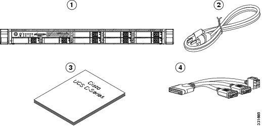
Boxed Contents
Server (Ciscon Connected Grid Appliance 220NH shown)
AC power cord (optional, up to two)
Documentation
KVM console cable
Cisco Connected Grid Appliance 220NH Server Overview
Figure 2

Overview
Installing the Server in a Rack

Note
Use this procedure to install the server into a rack using the toolless slide rails from Cisco:
Step 1
a.
b.
c.
Figure 3
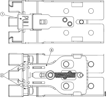
Opening the Front Securing Latch
Clip marked "PULL" on rear of assembly
Front mounting pegs
Spring-loaded securing latch on front of assembly
Step 2
a.
b.
Note
c.
d.
e.
f.
Figure 4
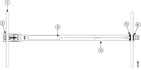
Attaching the Slide-Rail Assembly
Front-left rack post
Length-adjustment bracket
Front mounting pegs
Rear mounting pegs
Slide-rail assembly
Rear securing latch
Step 3
a.
b.
c.
Step 4
Note
a.
Note
b.
c.
Figure 5
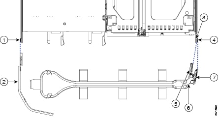
Attaching the Optional Cable Management Arm
Connecting and Powering On
Use this procedure to begin the installation process for the base operating system for the CGDS - Substation Workbench server software, Red Hat Enterprise Linux (RHEL) 6.3. Note that the Connected Grid Appliance 220NH does not include an internal optical drive, installation of RHEL 6.3 via the Installation DVD requires the use of an external DVD drive (not included) or equivalent.
Step 1
Step 2
Step 3
Step 4
Step 5
Step 6
Step 7
Step 8
Note
Note
This document is to be used in conjunction with the documents listed in the "Related Documentation <required for IOS - optional for other>" section.
Cisco and the Cisco logo are trademarks or registered trademarks of Cisco and/or its affiliates in the U.S. and other countries. To view a list of Cisco trademarks, go to this URL: www.cisco.com/go/trademarks. Third-party trademarks mentioned are the property of their respective owners. The use of the word partner does not imply a partnership relationship between Cisco and any other company. (1110R)
Any Internet Protocol (IP) addresses and phone numbers used in this document are not intended to be actual addresses and phone numbers. Any examples, command display output, network topology diagrams, and other figures included in the document are shown for illustrative purposes only. Any use of actual IP addresses or phone numbers in illustrative content is unintentional and coincidental.
© 2013 Cisco Systems, Inc. All rights reserved.
 Feedback