Cisco Cloud Security 1.0, Design Guide
Bias-Free Language
The documentation set for this product strives to use bias-free language. For the purposes of this documentation set, bias-free is defined as language that does not imply discrimination based on age, disability, gender, racial identity, ethnic identity, sexual orientation, socioeconomic status, and intersectionality. Exceptions may be present in the documentation due to language that is hardcoded in the user interfaces of the product software, language used based on RFP documentation, or language that is used by a referenced third-party product. Learn more about how Cisco is using Inclusive Language.
- Updated:
- June 25, 2014
Chapter: Cloud Security Design Details
Cloud Security Design Details
Data security breaches, intrusions, and malware attacks occur many times every day and can be active for long periods without system owners even detect the breaches. Often, detection occurs after the damage is done, and can require huge efforts to mitigate. Successful attacks can hurt reputations, cost lots of money, and erode customer trust.
Most of the time malware takes at least a week or two to detect and identify. Due to this length of duration it is extremely difficult and sometimes impossible to identify infected devices on the network. It is critical to identify malware infection as quickly as possible so that appropriate action can be taken to quarantine an infection, stop it from spreading, and clean infected systems.
When SPs and enterprises deploy cloud data centers, they must determine security requirements based on the type of deployment and the services being provided. Different vertical industries require different levels of data center and network security when deployed in the cloud.
To address these issues, the VMDC Cloud Security 1.0 solution focuses on guidance and gap analysis to mitigate cyber threats and security risks and enable cloud providers to achieve industry standard compliances efficiently and cost effectively reducing huge operation cost.
To deploy this architecture and support various vertical industries such as, health care, finance, and federal government, the VMDC Cloud Security 1.0 solution integrates additional critical security components with the VMDC 2.3 reference architecture to provide better, more efficient security and compliance.
When cloud services are provided in multi-tenant environments in which multiple tenants share the same network infrastructure and compute and storage resources, the separation, segmentation, and security of each tenant is extremely important.
Secure separation, or multi-tenancy, separates workloads and virtual machines (VMs) to meet tenant (customer) separation, security, compliance, and service-level agreement (SLA) requirements while sharing a compute, storage and networking infrastructure. Today’s consolidated data centers and clouds have disparate user groups with needs that range from simple segmentation to complete separation of network traffic and strict access control policies, even though they share the same physical servers and networks.
Data centers based on Virtualized Multiservice Data Center (VMDC) reference architecture consist of network, storage, and compute resources. Such data centers are typically interconnected and provide access to WANs, IP and Next Generation Networks (NGN), and the public Internet. VMDC-based data centers support multi-tenancy and multi-services, and provide management elements for administrative functions, orchestration (cloud portals, service catalog, and workflow automation), and assurance.
VMDC 2.3 Reference Architecture
The VMDC 2.3 reference architecture is a hierarchical layered model based on virtual port channel (vPC) technology. The benefits a hierarchical model provides, include scalability, resilience, performance, maintainability, and manageability. The hierarchical design represents a structured approach to building data center infrastructures, enabling relatively easy expansion in modular increments.
http://www.cisco.com/c/en/us/td/docs/solutions/Enterprise/Data_Center/VMDC/2-3/design_guide/VMDC_2-3_DG.pdf
Redundant nodes and links at each layer ensure no single points of failure, while link aggregation can be engineered for optimal bandwidth and performance. Devices in each layer perform similar functions, and this consistency simplifies troubleshooting and configuration. This results in easier, less expensive maintenance and plays key roles in security and compliance.
In data center deployments, WAN/provider edge (PE) routers act as a perimeter to the enterprise WAN or service provider (SP) IP/NGN backbone and the public Internet. These perimeter nodes may be dedicated to Layer 3 (L3) routing functions or may provide multiple services, such as Layer 2 (L2) interconnects between data centers along with L3 services.
Figure 3-1 shows the physical topology of the VMDC 2.3 reference architecture.
Figure 3-1 VMDC 2.3 Reference Architecture Physical Topology

In the VMDC 2.3 reference architecture, the infrastructure comprises of Cisco Nexus 7000 Series switches serving as aggregation nodes, and Cisco Nexus 5000 Series switches serving as access nodes. These switches support fine-tuning of port capacity and bandwidth to the level of aggregation or access density required to accommodate current and anticipated scale requirements. VMDC 2.3 was validated with ACE 4710 load balancer at that time, and now it is recommended to use Citrix SDX.
In the VMDC Cloud Security 1.0 reference architecture, Cisco ASR 1000 Series Aggregation Services Routers (ASR 1000) are used as WAN/PE routers, Nexus 7004 switches are used as aggregation devices, and Nexus 5548 switches are used as access devices. As shown in Figure 3-1, in the services layer the Cisco Adaptive Security Appliance (ASA) 5585 is used as a physical appliance for firewall protection.
Figure 3-2 shows the logical topology of the VMDC 2.3 system.
Figure 3-2 VMDC 2.3 Reference Architecture Logical Topology
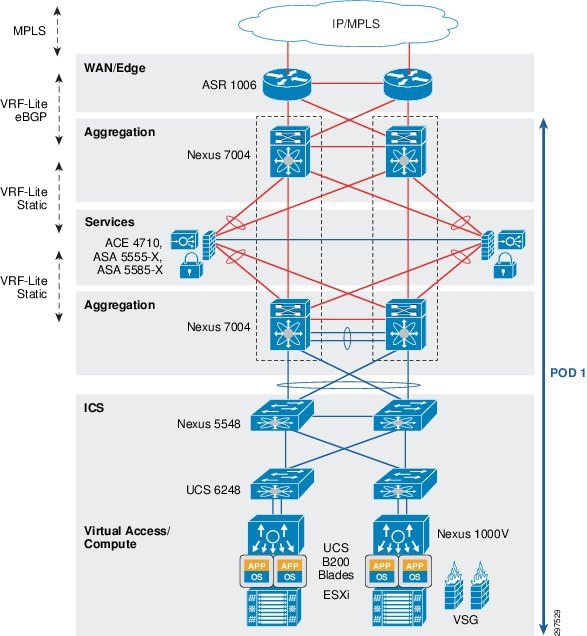
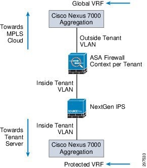
Figure 3-3shows how the Nexus 7004 aggregation switches are logically split to support front-end virtual routing and forwarding (VRF) and backend-protected VRF.
Figure 3-3 Nexus 7004 Aggregation Switches Supporting Front-End and Back-End VRF
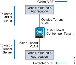
In the VMDC 2.3 reference architecture, ASA firewalls are deployed in multi-context L3 routed mode. Static routes are defined on the Nexus 7004 switch that direct traffic for each tenant to a specific outside VLAN toward the ASA. After the ASA receives traffic on a tenant context, the ASA applies the necessary security policies and maps the traffic on the inside tenant VLAN. The Nexus 7004 switch receives this on a separate inside VRF (protected VRF) and then maps the L3 traffic to a tenant L2 VLAN toward the compute stack.
VMDC Cloud Security Reference Architecture
The VMDC Cloud Security 1.0 reference architecture is based on the VMDC 2.3 vPC-based reference architecture. The layers and components are similar to VMDC 2.3, with the addition of security elements (Figure 3-4).
Figure 3-4 VMDC Cloud Security 1.0 Security Elements
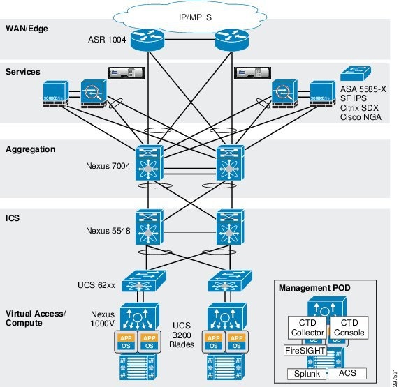
Figure 3-6 shows the VMDC Cloud Security 1.0 logical topology
Figure 3-5 VMDC Cloud Security 1.0 Security Logical Topology
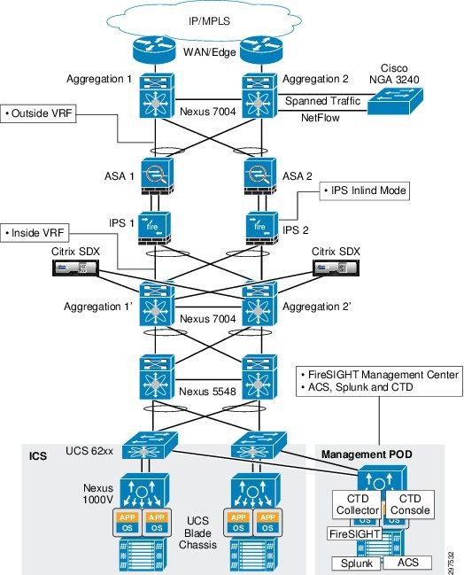
As shown in Figure 3-6, tenant traffic that goes to the ASA firewall goes through NGIPS because NGIPS sits in line, with physical connectivity between the ASA firewalls and Nexus 7004 aggregation switches.
Figure 3-6 Traffic Flow—Nexus 7004 Switches, ASA, and NGIPS
NGIPS, deployed in transparent bridge mode, inspects traffic based on VLAN tags per tenant. When traffic reaches the inline NGIPS, NGIPS inspects traffic based on the tenant VLAN configuration and applies access policies and other deep inspection policies.
VMDC Cloud Security 1.0 Tenant Containers
The VMDC 2.3 reference architecture supports multiple network containers, which are also called consumer models. The consumer models are described in greater detail in VMDC 2.3 documentation.
This section describes the consumer models validated for VMDC Cloud Security 1.0. VMDC Cloud Security 1.0 supports the previously defined VMDC 2.3 consumer models, the same concepts of security features can be applied to other VMDC architectures. However, VMDC Cloud Security 1.0 validation focuses on Gold and Copper containers, which cover most VMDC 2.3 public and private cloud deployments.
Depending on VMDC container type, traffic may or may not go through security devices, based on subscribed services. However, because SPs must protect their data centers, traffic entering and leaving a multiservice data center must be monitored and inspected, and complete data center visibility is required. Hence, the VMDC 2.3 Gold and Copper network containers (which contain the ASA based perimeter FW service) are relevant for inserting NGIPS services as part of this VMDC Cloud Security 1.0 solution validation. It is also to be noted that while the security concepts in this solution are overlaid on the VMDC 2.3 architecture and container models, the same concepts can also be applied to other VMDC architectures like VMDC 3.0 etc.
To monitor all traffic, even traffic that does not go through a firewall and other security devices, we recommend using NetFlow to capture traffic from various locations in the data center, and using Syslog from all key network and security elements, including but not limited to aggregation, access, and virtual switches, along with firewalls, to provide complete data center visibility.
VMDC Cloud Security 1.0 Gold Container
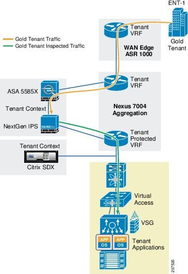
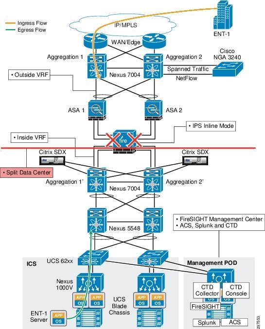
A Gold container, with perimeter firewall, VSG, NGIPS, and server load balancer services, provides a higher degree of security and availability because each gold tenant is assigned a separate context or virtual firewall instance. Traffic for this container goes through NGIPS inspection, providing a higher degree of security for the tenant.
As shown in Figure 3-7, an NGIPS is physically in line between the ASA firewall and the Nexus 7004 switch. The traffic for the gold tenant received on the tenant outside VRF is first sent through the ASA firewall context, which applies the necessary access control policies and sends out the traffic on the gold tenant VLAN. Traffic on the inside VLAN goes through NGIPS, which applies the necessary inspection policies and passes the traffic to the Nexus 7004 aggregation switch, into the gold tenant inside (protected) VRF.
Figure 3-7 VMDC Cloud Security 1.0 Gold Container Topology
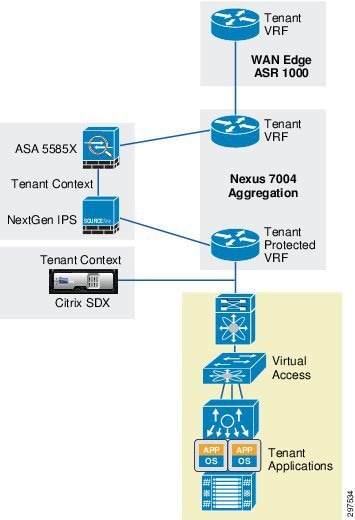
Figure 3-8 shows the Gold tenant traffic flow in VMDC Cloud Security 1.0.
Figure 3-8 VMDC Cloud Security 1.0 Gold Tenant Traffic Flow
VMDC Cloud Security 1.0 Copper Container
This tenancy model, designed to provide higher tenancy scale in VMDC 2.3 deployments, is suitable for Internet access to cloud resources. The Copper container is useful for SMB customers that require one VLAN and a handful of VMs in the cloud. Such customers require isolation and security, but typically do not want to pay higher fees for using their own virtual firewall context or deep packet inspection (DPI). The Copper container is designed such that all Copper tenants share the same VFW context. Copper containers consume fewer firewall contexts and VRF/BGP resources on the WAN edge and Nexus 7004 nodes.
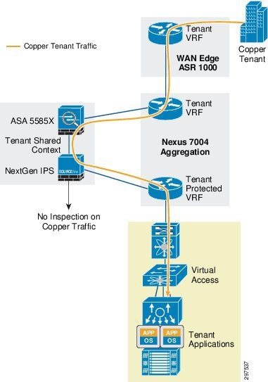
The Copper tenant service level is generally lower than the Gold tenant service level. SPs may not want to use NGIPS resources to inspect copper tenant traffic, which may not require the higher level of security.
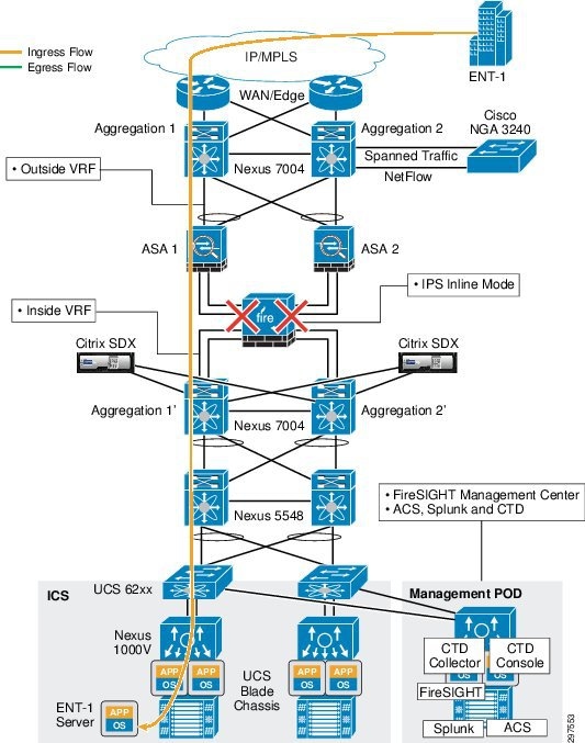
In a VMDC Cloud Security 1.0 Copper container, tenant traffic shares the global VRF when entering the data center. This saves some resources because there are fewer VRFs on the Nexus 7004 aggregation switch. Multiple Copper tenants also share a firewall context. The firewall applies the necessary access control policies and passes Copper tenant traffic back to the aggregation switch. Because NGIPS physically sits in line between the firewall and the aggregation switch, Copper tenant traffic (each Copper tenant has their own VLANs) is marked as trusted; NGIPS does not inspect Copper tenant traffic.
Figure 3-9 shows the VMDC Cloud Security 1.0 Copper container topology.
Figure 3-9 VMDC Cloud Security 1.0 Copper Container Topology
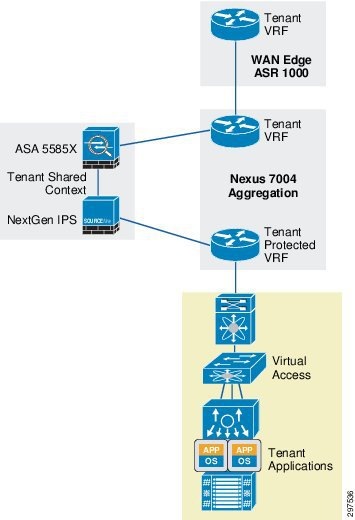
Figure 3-10 shows the Copper tenant traffic flow in VMDC Cloud Security 1.0.
Figure 3-10 VMDC Cloud Security 1.0 Copper Tenant Traffic Flow
VMDC Cloud Security 1.0 Bronze Container
Tenants boarded on Bronze containers maintaining their own separation to keep the threat localized in one container. On the other hand Bronze tenants receive the virtual firewall services VSG to provide intra tenant separation and security.
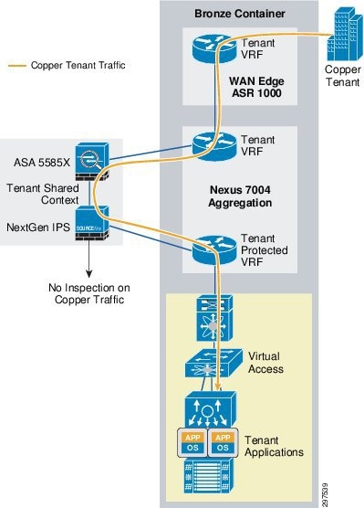
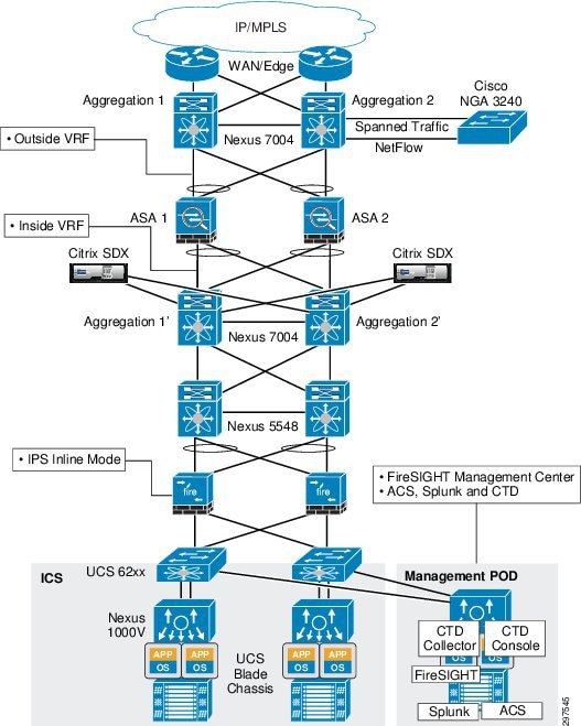
The Bronze container is the simplest and the most basic container; its traffic does not go through a firewall or NGIPS, even though the firewall and NGIPS are connected inline to the aggregation node.
Figure 3-11 shows the VMDC Cloud Security 1.0 Bronze container topology.
Figure 3-11 VMDC Cloud Security 1.0 Bronze Container Topology
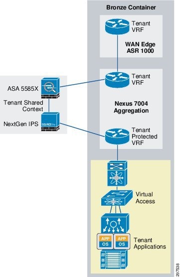
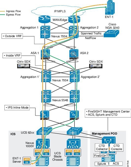
Figure 3-12 shows the Bronze tenant traffic flow in VMDC Cloud Security 1.0.
Figure 3-12 VMDC Cloud Security 1.0 Bronze Tenant Traffic Flow
VMDC Cloud Security 1.0 Silver Container
Tenants boarded on Silver containers do not receive security services except for VSG from the cloud.
The Silver container is just like the bronze one with optional one-arm load balancer capability. The Silver container traffic does not go through a firewall or NGIPS, even though the firewall and NGIPS are connected inline to the aggregation node. For further details, refer to the VMDC 2.3 design guide.

Note![]() The Silver Container model is not tested in VMDC Cloud Security release 1.0.
The Silver Container model is not tested in VMDC Cloud Security release 1.0.
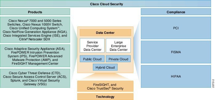
VMDC Cloud Security Solution Fundamental Pillars
The Virtualized Multiservice Data Center (VMDC) Cloud Security solution is built on three fundamental pillars. Figure 3-13 shows a holistic view of the VMDC Cloud Security 1.0 solution and its fundamental pillars: Products, Technology, and Compliance. These in turn enable service providers (SPs) to securely deploy public, private, and hybrid cloud data centers based on the multi-tenant VMDC 2.3 architecture.
Figure 3-13 Fundamental VMDC Cloud Security 1.0 Pillars
Key functionality covered in this solution includes:
- Tracking suspicious activity and threats
- Re-mediating vulnerabilities and mitigating attacks
- Network behavior analysis
- Active traffic monitoring in all directions
- Dedicated flow analysis for threat detection, behavioral analysis and forensics
- Centralized log collection from network and storage devices
- Industry standards and regulatory compliance
An effective security design requires complementary security services at appropriate points in the data center network, including:
- Defending the data center from unauthorized users and outside attacks
- Preventing intrusion and malware
- Defending the tenant edge with a proven firewall to secure the virtual and cloud infrastructures
- Assigning virtual machines (VMs) to segmented trust zones in the network and enforcing access policies at the virtual server level
- Providing centralized multi-tenant policy management
- Supporting VM mobility
- Separating security, network and server administrator duties
- Secure data center and applications access
- Scalability with the rest of the cloud infrastructure
VMDC Cloud Security 1.0 is based on the VMDC 2.3 virtual port channel (vPC)-based reference architecture. To provide more effective and robust security, VMDC Cloud Security 1.0 adds the following security elements:
VMDC Cloud Security Design Considerations
The following Cloud security design considerations are recommended:
Access Control
In the VMDC Cloud Security 1.0 reference architecture, a pair of ASA 5585 access control firewalls is used to minimize the impact of unwanted network access to the data center. Figure 3-14 illustrates this access control.
Figure 3-14 Access Control Using the ASA 5585 Firewall
The ASA 5585 firewall pair is used in active/active mode and is configured in multi-context routing mode. The secure inside network must be in a separate subnet from client subnets and the outside network. In multi-context mode, virtual contexts are configured on the ASA firewall pair, dividing each into multiple logical firewalls. Each logical firewall can support different interfaces and policies.
On each of the ASA 5585 firewall pair, half of the tenant contexts are active and half of the tenant contexts are inactive. This protects all tenants; in the event that one of the ASA 5585 firewall pair fails, the remaining firewall successfully supports all tenants, as shown in Figure 3-15.
Figure 3-15 ASA 5585 Pair in Active/Active Mode
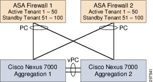
The ASA 5585 firewall pair create the dual-home to the data center aggregation nodes using two 10-Gigabit Ethernet (10 GbE) links for resiliency. The two links on each firewall are configured as an EtherChannel to provide both load balancing and responsive failure recovery. The vPC feature on the Cisco Nexus 7000 data center aggregation switches enables the firewall EtherChannel to span the two data center aggregation switches while appearing to be connected to one upstream switch. This EtherChannel link is configured as a VLAN Trunk to support access to multiple secure VLANS in the data center.
Site to Site VPN
In VMDC Cloud Security 1.0, data center ASA may be used for site-to-site VPN which potentially eliminates the need for another physical VPN concentrator. For further details, refer to the link below:
http://www.cisco.com/c/en/us/support/docs/cloud-systems-management/configuration-professional/112153-ccp-vpn-asa-router-config-00.html
Secure Remote Access VPN
A pair of ASA in active/standby is required to provide secure remote access VPN (RA-VPN) services from the service provider cloud. For further details, refer to the link below:
http://www.cisco.com/c/en/us/td/docs/solutions/Enterprise/Data_Center/VMDC/2-3/design_guide/VMDC_2-3_DG.pdf
NGIPS Integration
In VMDC Cloud Security 1.0, FirePOWER Next Generation Intrusion Prevention System (NGIPS) performs line-rate deep traffic inspection.
To secure data center deployments, SPs require complete visibility into their entire networks, for users, infrastructure, devices, services, and resources. To prevent all threats, SPs must cover the full attack continuum that occurs before, during, and after attacks. Following these steps prevents the occurrence of the same threat.
Figure 3-16 shows the steps and elements help achieve strong, effective defense against the threat-centric attack continuum.
Figure 3-16 Threat-Centric Attack Continuum
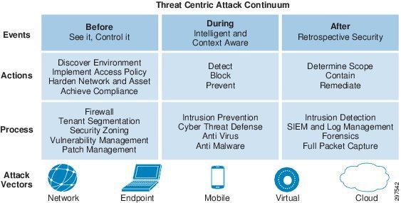
As shown in the above diagram, with all the mobility and virtualization, there are now many different attack vectors such as Mobile users, Virtual desktops etc. This increases the chances of threat and security concerns.
In VMDC Cloud Security Release 1.0, the ASA firewall is used for access control. This protects the data center from outsiders and limits the access based on the policies defined for trusted users and applications. This allows only trusted users/tenants into the data center, but if the trusted users send malicious traffic, the firewall cannot detect it.
To protect the data center during the normal operation, line rate non-blocking inspection is a necessity. The Cisco FirePOWER next generation IPS provides the capability to inspect all the traffic in and out of the cloud data center at a line rate. The next generation IPS provides malware protection and intrusion prevention by stopping the exploits, hackers, attacks. It also provides application control and URL filtering which can be implemented on a per tenant basis. During the normal operation, Cisco Cyber threat defense provides in-depth visibility by collecting Netflow and NSEL streams of data. This can help cloud providers to actively monitor any threat.
In case of data security breach, cloud providers need tools that isolate the incident without compromising the entire the data center. So that the tenant can trace the breach to its source, the provider can use multiple security techniques, such as, proper separation of tenants, Intrusion detection, and log monitoring. The log monitoring also helps later in terms of investigation and forensic activity.
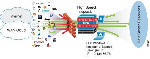
Integrating FirePOWER NGIPS into the VMDC Cloud Security 1.0 reference architecture provides point-in-time detection of any malware or threat, leveraging big data analytics and a continuous analysis capability to confirm an infection, trace its path, analyze its behavior, re-mediate its target, and report its impact regardless of when a file is determined to be malware.
NGIPS enables SPs to look deeply into a device and provides the following information:
1.![]() How did the threat get onto the device?
How did the threat get onto the device?
3.![]() What communications were made from the infected device?
What communications were made from the infected device?
4.![]() What is the chain of events?
What is the chain of events?
This information enables SPs to take timely, appropriate action to avoid downtime and provide the most secure environment to their tenants.
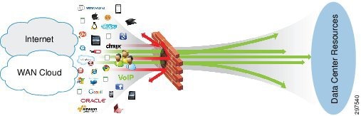
Policy and control using firewalls and other techniques reduce only the surface area of an attack. In theory this approach makes sense, but in practice this approach fails when trusted persons or devices initiate attacks. No matter how large or small a security gap is, the bad people will find it and try to exploit it. It is no longer safe to assume that what is permitted in a network or data center is good. Having a high speed inspection engine that can inspect all content traveling in and out of a data center to detect, understand and stop threats is the recommended way to ensure that identified threats can no longer enter the data center.
Figure 3-17 shows that even after deploying firewalls, infected traffic may get through it. Hence, high-speed inspection is required to block, mitigate, or quarantine such infections.
Figure 3-17 Threat Penetrations despite Firewalls and control policies
FirePOWER NGIPS combines the security of an industry-leading IPS with the power to control network access based on detected applications, users, and URLs.
In VMDC Cloud Security 1.0, NGIPS is deployed inline and can:
- Gather detailed information about hosts, operating systems, applications, users, files, networks, and vulnerabilities.
- Block or permit network traffic based on various network-based criteria, along with other criteria including applications, users, URLs, IP address reputations, and the results of intrusion or malware inspections.
- Be deployed in fail-safe or fail-open mode, depending on the deployment requirement.
Intrusion detection and prevention enables SPs to monitor data center network traffic for security violations and, in inline IPS deployments, enable them to block or alter malicious traffic. Intrusion prevention is integrated into access control, in which SPs can associate intrusion policies with specific access control rules. If network traffic meets the conditions in a rule, NGIPS can analyze matching traffic using an intrusion policy.
NGIPS can be deployed in fail closed or fail open modes. This feature enables service provider to decide what action need to be taken during the failure of an IPS appliance.
Table 3-1 shows the availability of the failure modes for the hardware models:
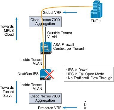
As shown in Figure 3-18 fail close mode is supported on all NGIPS models. In fail close mode, NGIPS shuts down traffic through the appliance, so packets cannot pass through NGIPS sensor on any NGIPS interfaces.
The VMDC Cloud Security 1.0 solution supports fully redundant HA design for all links and network components. We recommend deploying NGIPS in a fail-safe mode so that a single appliance failure routes traffic to the secondary path and minimizes the downtime of any services running in the data center. When deploying NGIPS in a fail close mode, all inspection flows dropped from the failed NGIPS are picked up by the secondary NGIPS in the middle. The secondary NGIPS starts building the flows as more packets pass through.
Note![]() To ensure no packet loss from inspection even if NGIPS picks up flows in the middle, or to deal with the asymmetrical traffic flows, the STRICT TCP enforcement box must not be checked at the IPS interface level during the initial configuration.
To ensure no packet loss from inspection even if NGIPS picks up flows in the middle, or to deal with the asymmetrical traffic flows, the STRICT TCP enforcement box must not be checked at the IPS interface level during the initial configuration.
Note![]() It is not recommended to deploy single NGIPS in a fail close mode. If a single NGIPS deployed in the data center inline between the aggregation and access layers, in case of NGIPS failure, all the services go down and no traffic or data can pass through the NGIPS appliance.
It is not recommended to deploy single NGIPS in a fail close mode. If a single NGIPS deployed in the data center inline between the aggregation and access layers, in case of NGIPS failure, all the services go down and no traffic or data can pass through the NGIPS appliance.
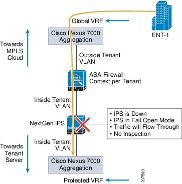
NGIPS fail open mode is available depending on hardware platform and interface module type used in the physical appliance. When NGIPS is configured in fail-open mode and there is a failure of either the appliance or ingress or egress links, the NGIPS appliance closes a mechanical relay in the appliance, enabling packets to flow through it. In this case, there is no data inspection or monitoring. Instead, traffic flows transparently without interruption of active services.
Figure 3-19 shows the flow of traffic during fail open mode.
Figure 3-19 Fail Open Mode Traffic Flow
When a failure occurs and NGIPS goes into fail open mode, some security gaps occur for the duration of the failure. During this time, any malware or intrusions that penetrate the data center using this route are not captured and impose a risk even after NGIPS recovers from the failure.
Note![]() Recommendation is to configure redundant NGIPS in fail close (fail closed) mode. If a failure occurs on any side of a network or security component, this enables traffic to move to the second NGIPS.
Recommendation is to configure redundant NGIPS in fail close (fail closed) mode. If a failure occurs on any side of a network or security component, this enables traffic to move to the second NGIPS.
SPs typically deploy VMDC in multi-tenant environments using overlapping IP addresses. This enables faster tenant deployment and minimizes operation costs for IP management and maintenance.
In VMDC deployments, overlapping IP address scheme for tenants prevents FireSIGHT Management Center and FireSIGHT technology from capturing and reporting based on unique IP addresses.
The following example shows an SP enabling the hosts monitoring feature on the FireSIGHT Management Center in an overlapping IP address environment:
1.![]() Host A, with IP address 10.10.10.1, runs Linux in VMDC tenant container A; FireSIGHT Management Center detects a malware file.
Host A, with IP address 10.10.10.1, runs Linux in VMDC tenant container A; FireSIGHT Management Center detects a malware file.
2.![]() Host B, with the same IP address (10.10.10.1) runs Windows in VMDC tenant container B; FireSIGHT Management Center detects an intrusion.
Host B, with the same IP address (10.10.10.1) runs Windows in VMDC tenant container B; FireSIGHT Management Center detects an intrusion.
3.![]() Host C, with the same IP address (10.10.10.1) runs a different version of Linux; FireSIGHT Management Center detects a malware file and receives the cloud disposition of unknown.
Host C, with the same IP address (10.10.10.1) runs a different version of Linux; FireSIGHT Management Center detects a malware file and receives the cloud disposition of unknown.
As noted, the three hosts have the same IP address although they belong to three different tenant containers. This creates a disordered database showing same host deployed with multiple operating systems, multiple versions of same operating system, a malware detection alert, an intrusion alert, and at the same time malware detect with unknown disposition.
In this situation, it is extremely difficult to locate the actual hosts and which tenant containers they belong to. In the preceding example, three hosts have issues in three tenant containers, and The SP may be unable to locate the exact host to take appropriate action to defend against the threats.
To overcome the overlapping IP address issue, we recommend using VLAN tagging to isolate hosts in each tenant container, as shown in the following example.
1.![]() Host A, with IP address 10.10.10.1 and VLAN tag 100, runs Linux in VMDC tenant container A; FireSIGHT Management Center detects a malware file.
Host A, with IP address 10.10.10.1 and VLAN tag 100, runs Linux in VMDC tenant container A; FireSIGHT Management Center detects a malware file.
2.![]() Host B, with the same IP address (10.10.10.1) with VLAN tag 200, runs Windows in VMDC tenant container B; FireSIGHT Management Center detects an intrusion.
Host B, with the same IP address (10.10.10.1) with VLAN tag 200, runs Windows in VMDC tenant container B; FireSIGHT Management Center detects an intrusion.
3.![]() Host C, with the same IP address (10.10.10.1) with VLAN tag 300, runs a different version of Linux; FireSIGHT Management Center detects a malware file and receives the cloud disposition of unknown.
Host C, with the same IP address (10.10.10.1) with VLAN tag 300, runs a different version of Linux; FireSIGHT Management Center detects a malware file and receives the cloud disposition of unknown.
Each host belongs to a specific VLAN in a tenant container, so for intrusion detection, FireSIGHT Management Center can notify the event using the VLAN tag. This enables SPs to pinpoint infected devices and take appropriate action to mitigate or quarantine them.
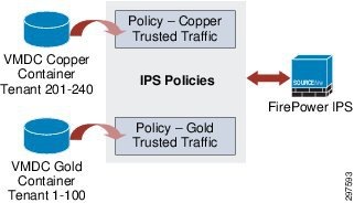
When deploying multiple tenants, each tenant will belong to a type of container, either Gold, Silver and so on, as shown below:
Figure 3-20 Multiple Tenant Container Types
Note![]() When configuring an IPS policy per container type, all tenants on the container type receive the same policy. This helps service providers significantly in terms of operations and maintenance.
When configuring an IPS policy per container type, all tenants on the container type receive the same policy. This helps service providers significantly in terms of operations and maintenance.
Note When performing changes to an IPS policy that impacts memory allocations (increase or decrease), the SNORT process may restart and the IPS sensor may not process packets for a short period of time. The period of time varies depending on the load and the number of polices applied. As a best practice, we recommend defining one policy per VMDC container model to improve performance. It is recommend that when modifying or adding new IPS polices policy changes should be carried out during scheduled maintenance windows. To inspect all the traffic during a maintenance window, we recommend diverting the traffic to the failover IPS within the data center before performing maintenance work to minimize any unforeseen downtime.
Use the Firesight Management Console to deploy intrusion policies with tiers of service. For example, you can define three IPS policies to represent three tiers of service:
Any IPS policy can be referenced more than once in the Access Control policy, and events are separated by VLAN tags for different clients. This approach streamlines the IPS / IDS enforcement per rule in the Access Control policy. A rule in the Access Control policy can reference either a single client or entire tier of service.
For malware detection, FireSIGHT Management Center cannot use VLAN tag association; instead, SPs must build per-tenant file policies and assign the policies in malware rules to detect individual hosts in a tenant container. This enables SPs to isolate infected hosts in a specific tenant container for malware detection.
For application monitoring, we recommend enabling application discovery under the network discovery portion of FireSIGHT Management Center. In SP environments, tenant applications may use overlapping IP addresses. Although application discovery may have the same issues as hosts with overlapping IP addresses, this at least gives SPs a high-level view of what applications are running, and if there are any specific threats to these applications, FireSIGHT Management Center adjusts the threat level accordingly.
FirePOWER FireSIGHT Management Center
FirePOWER FireSIGHT Management Center provides a centralized management console and event database repository for FirePOWER NGIPS. FireSIGHT Management Center aggregates and correlates intrusion, file, malware, discovery, connection, and performance data, assessing the impact of events with indications of compromise. This enables SPs to monitor what data center devices report in relation to other devices, and to assess and control the activity that occurs in a data center.
FireSIGHT Management Center can be deployed in a fully redundant mode to ensure continuous operation. The FireSIGHT Management Center pair shares policies, user accounts, and configurations. Events are sent to both systems in the redundant pair.
FireSIGHT Management Centers periodically update each other on configuration changes, and changes made to one system are applied to the other. Each FireSIGHT Management Center has a five-minute synchronization cycle, but the cycles themselves can be out of synchronization by as much as five minutes, so changes appear within two five-minute cycles. During this ten-minute window, configurations may differ on the paired FireSIGHT Management Centers.
FireSIGHT Management Centers in a high availability pair share the following information:
- User account attributes
- Authentication configurations
- Custom user roles
- Authentication objects for user accounts and user awareness, as well as the users and groups that are available to user conditions in access control rules
- Custom dashboards
- Custom workflows and tables
- Device attributes, such as the device’s host name, where events generated by the device are stored, and the group in which the device resides
- Intrusion policies and their associated rule states
- File policies
- Access control policies and their associated rules
- Local rules
- Custom intrusion rule classifications
- Variable values and user-defined variables
- Network discovery policies
- User-defined application protocol detectors and the applications they detect
- Activated custom fingerprints
- Host attributes
- Network discovery user feedback, including notes and host criticality; deletion of hosts, applications, and networks from the network map; and deactivation or modification of vulnerabilities
- Correlation policies and rules, compliance white lists, and traffic profiles
- Change reconciliation snapshots and report settings
- Intrusion rules, geo-location database (GeoDB), and vulnerability database (VDB) updates
When deploying HA FireSIGHT Management Centers, managed NGIPS are configured to send event data to both systems. If a system fails, SPs can use the redundant system to monitor the network without interruption.
When deploying redundant FireSIGHT Management Centers, both physical appliances must be identical, and both must run the same software and firmware versions. This protects the reporting and cloud disposition feature in case of single appliance failure without any downtime.
Table 3-2 compares the services available after a FireSIGHT Management Center failure when deploying one FireSIGHT Management Center with those available with a redundant FireSIGHT Management Center deployment.
Note![]() FireSIGHT Management Center HA is outside the scope of VMDC Cloud Security 1.0.
FireSIGHT Management Center HA is outside the scope of VMDC Cloud Security 1.0.
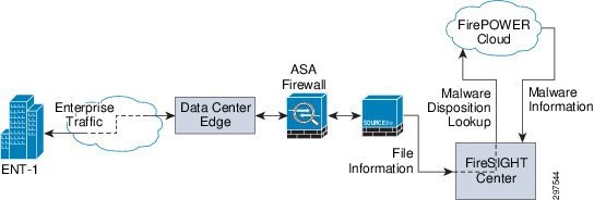
FireSIGHT Management Center Cloud Connectivity
To establish the FirePOWER cloud connectivity the FireSIGHT management system need to have an IP connectivity to the cloud. To achieve the connectivity, the malware license installation has to be completed. Once the license is installed, configure the FireSIGHT management system with TCP port 32137 to establish the bi-directional cloud connectivity.
Figure 3-21 FireSIGHT Management Center Cloud Connectivity
Note![]() In case of FireSIGHT management center failure (single FireSIGHT management center deployment model), the appliance will loose the capability of getting a malware disposition from the Cisco FirePOWER cloud.
In case of FireSIGHT management center failure (single FireSIGHT management center deployment model), the appliance will loose the capability of getting a malware disposition from the Cisco FirePOWER cloud.
Single FireSIGHT Management Center Deployment failure:
1.![]() When using the single FireSIGHT Management Center deployment model, the network can no longer get malware and cloud dispositions from the FirePOWER cloud, and URL filtering no longer work.
When using the single FireSIGHT Management Center deployment model, the network can no longer get malware and cloud dispositions from the FirePOWER cloud, and URL filtering no longer work.
2.![]() The NGIPS appliance blocks malware based on a pre-configured malware policy.
The NGIPS appliance blocks malware based on a pre-configured malware policy.
3.![]() Pre-configured control policies continue to work without FireSIGHT Management Center
Pre-configured control policies continue to work without FireSIGHT Management Center
4.![]() The NGIPS appliance locally stores all events during the FireSIGHT Management Center failure. After FireSIGHT Management Center becomes available, NGIPS synchronizes events with Management system and updates all logs.
The NGIPS appliance locally stores all events during the FireSIGHT Management Center failure. After FireSIGHT Management Center becomes available, NGIPS synchronizes events with Management system and updates all logs.
In FireSIGHT Management Center, the relationship between file type events and malware events is important. If a file policy is configured to perform malware cloud lookup, the returned dispositions can be one of the following:
When the disposition is clean, no action is taken and data flows normally. When the disposition is malware, FireSIGHT Management Center, based on its configuration, acts on the file and blocks it. If the disposition is unknown, the system keeps the file in a monitor mode to see whether the disposition changes to malware in the near future. If an unknown file type turns out to be malware, FireSIGHT Management Center blocks the file.
FireSIGHT Management Center System Requirements
Table 3-3 summarizes the system requirements for FireSIGHT Management Center.
|
|
|
|
|
|---|---|---|---|
Note![]() The maximum number of NGIPS depends upon NGIPS type and event rate.
The maximum number of NGIPS depends upon NGIPS type and event rate.
FirePOWER FireSIGHT is a discovery and awareness technology that collects information about hosts, operating systems, applications, users, files, networks, geo-location, and vulnerabilities to provide a comprehensive view of the data center network.
The FireSIGHT Management Center web interface provides a view of data collected by FireSIGHT. SPs can use this data to perform access control and modify intrusion rule states.
Access control is a policy-based feature that enables SPs to specify, inspect, and log traffic that can traverse their networks. An access control policy determines how the system handles network traffic. A policy that does not include access control rules handles traffic in one of the following ways (default action):
1.![]() Block all traffic from entering your network.
Block all traffic from entering your network.
2.![]() Trust all traffic to enter your network without further inspection.
Trust all traffic to enter your network without further inspection.
3.![]() Allow all traffic to enter your network, and inspect the traffic with a network discovery policy only.
Allow all traffic to enter your network, and inspect the traffic with a network discovery policy only.
4.![]() Allow all traffic to enter your network, and inspect the traffic with intrusion and network discovery policies.
Allow all traffic to enter your network, and inspect the traffic with intrusion and network discovery policies.
For VMDC Cloud Security Release 1.0, Copper and Gold tenants are validated. Copper tenants share the same firewall context and the Copper tenant traffic goes through the inline IPS. Because most Copper tenants are SMB customers who do not need additional security, this traffic does not require inspection. Marking traffic as Trusted, prevents inspection.
Note![]() In this release, Bronze tenants were also tested, but this traffic does not go through the firewall and NGIPS
In this release, Bronze tenants were also tested, but this traffic does not go through the firewall and NGIPS
In VMDC Cloud Security 1.0, Copper tenants have separate server VLANs, even though they share the same firewall context and are segmented at L2. It is recommended to configure NGIPS with device fast-path rule in hardware for all the Copper or Silver tenants that may not require deep packet inspection.
SPs may include access control rules in access control policies to further define how traffic is handled by targeted devices, from simple IP address matching to complex scenarios involving different users, applications, ports, and URLs. A rule action is specified for each rule, that is, whether to trust, monitor, block, or inspect matching traffic with an intrusion or file policy.
In multi-tenant environments in which SPs use the overlapping IP addresses for tenants, the Cisco FirePOWER IPS can detect and mark per-tenant intrusion events based on VLAN tag. To get per-tenant malware events, SPs need to define per-tenant file policies.
Network-Based Advanced Malware Protection (AMP)
Network-based advanced malware protection (AMP) is a license based feature. AMP allows the system to inspect network traffic for malware in several types of files. Appliances can store detected files for further analysis. After NGIPS detects a file as a culprit, NGIPS submits the file to the FirePOWER cloud using FirePOWER FireSIGHT Management Center to perform a simple known-disposition lookup using the SHA-256 hash value of the file.
The following methods can determine whether a file is malware:
- SHA-256 hash—This method is fast and requires minimal communication with the FirePOWER cloud to get one of three malware dispositions for any file: Clear, Malware or Unknown. When malware lookup is based on file policy settings, NGIPS captures the file based on the tenant VLAN tag and calculates the SHA-256 hash value. This value is sent to FireSIGHT Management Center, which forwards the value to the FirePOWER cloud for malware disposition. The cloud lookup time for the disposition is typically under 200 msec.
- SPERO fingerprint—When this is enabled, NGIPS collects static file attributes and transmits the SPERO signature to the FirePOWER cloud. This can identify malware even if the specific file SHA hash value has not been observed.
- Sandbox file analysis—This feature can extract files from the network flow and submit them to the FirePOWER cloud for evaluation. Submission can be configured to be automatic or manual.
Automatic analysis is limited to Windows PE (executables) having unknown status. Manual submission supports a wide variety of file types, including MSEXE/DLL, JAR, PDF, SWF, DOC, DOCX, PPT, PPTX, XLX, XLSX, and RTF.
Using this technique, files are executed in the sandbox environment. Execution results in a threat score; the file can be marked as malware based on its threat score. Getting a threat score can take from 5 to 10 minutes. Sandbox file analysis do not block files, but subsequent detection of these files based on the SHA-256 enables to do a block action on the file.
Depending on the security requirements and threat, service provider configured the system to submit files for dynamic analysis, which produces a threat score. Using this contextual information, service provider can configure the system to block or allow specific files. It is recommended to configure malware protection as part of the overall access control configuration; file policies associated with access control rules inspect network traffic that meets rule conditions.
Table 3-4 shows different actions the FireSIGHT management center and IPS can take based on the file policy configurations.
|
|
|
|
|
|
|---|---|---|---|---|
Design Options for NGIPS in VMDC Cloud Security Architecture
The VMDC Cloud Security 1.0 architecture is based on the VMDC 2.3 vPC-based reference architecture to provide HA and better bandwidth between the vPC peers, such as between aggregation switches/access switches, and aggregation switches/services components.
In VMDC Cloud Security 1.0, NGIPS is deployed inline to enable SPs to protect entire data centers from attacks that might affect the availability, integrity, or confidentiality of hosts or devices in the SP network.
The VMDC Cloud Security 1.0 architecture is built so that traffic can flow asymmetrically when entering and exiting a data center. Because of asymmetrical data flows in data centers, NGIPS must be integrated into the architecture so that it is not affected by the asymmetrical traffic flow.
This section describes design considerations on how and where we can insert the FirePOWER next generation IPS in the VMDC 2.3 reference architecture in such a way that it will be less disruptive and provide scale and performance with high availability. There are multiple locations service provider may be able to insert the NGIPS within the VMDC 2.3 reference architecture. Below sections covered all such possibilities and provides the recommended method, that will integrate the NGIPS in such a way, the architecture integrity will not be compromised.
Inserting Multiple NGIPS at the Aggregation Layer (Recommended Design)
As shown in Figure 3-22, NGIPS can be inserted between the aggregation and access layer on each link to eliminate appliance failure as a single point of failure.
Figure 3-22 Inserting Multiple NGIPS between Aggregation and Access Layer
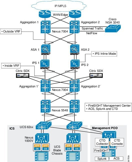
Table 3-5 summarizes the pros and cons of this deployment model.
|
|
|
|---|---|
Some Issue with Asymmetrical traffic in case of one IPS failure |
|
Note![]() Require a pair of NGIPS per Compute Pod (Vblock or FlexPod) when deploying IPS at the access layer.
Require a pair of NGIPS per Compute Pod (Vblock or FlexPod) when deploying IPS at the access layer.
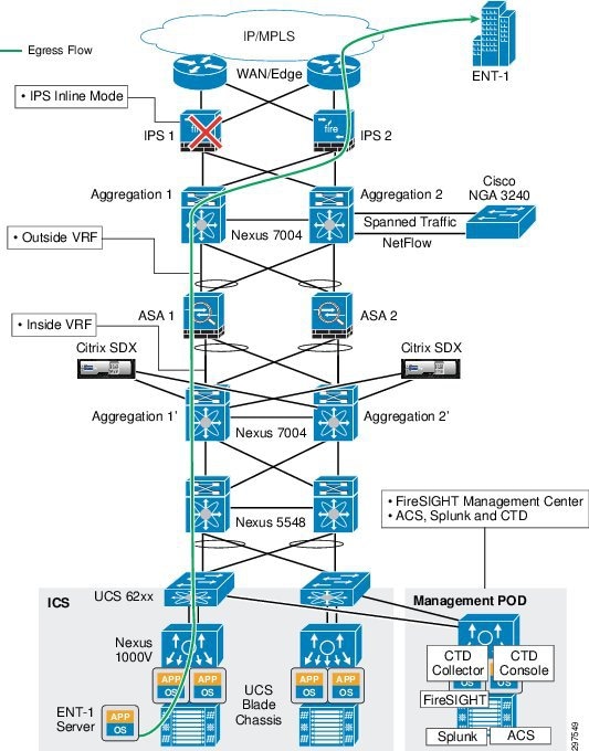
Figure 3-23 shows the data center ingress and egress traffic flows. Traffic may flow through one aggregation and access switch during ingress and may try to use the second access and aggregation switch on the egress path. Based on static routing configurations on the Nexus 7004 aggregation switches, traffic flows to specific ASAs from both aggregation switches as shown.
Figure 3-23 Ingress and Egress Traffic Flows
The VMDC Cloud Security 1.0 solution uses ASA in active/active mode. In this mode, each ASA services half of the data center tenants in an active state and rest of the data center tenants on standby. If an ASA fails, the second ASA can service all data service tenants without downtime.
To deploy NGIPS in a redundant mode, insert an NGIPS appliance physically inline between each Nexus 7000 aggregation switch and ASA firewall, as shown in Figure 3-24.
In this deployment model, traffic reroutes to the secondary path in the following situations:
1.![]() Complete ASA firewall appliance failure
Complete ASA firewall appliance failure
2.![]() Complete NGIPS appliance failure
Complete NGIPS appliance failure
3.![]() Both links fail between ASA and Nexus 7004 aggregation switch
Both links fail between ASA and Nexus 7004 aggregation switch
4.![]() One management link fails and one data link fails on ASA
One management link fails and one data link fails on ASA
5.![]() Both links fail between ASA and NGIPS
Both links fail between ASA and NGIPS
6.![]() Both links fail between NGIPS and Nexus 7004 aggregation switch
Both links fail between NGIPS and Nexus 7004 aggregation switch
Figure 3-24 Traffic Flows with ASA Firewall and IPS Failure
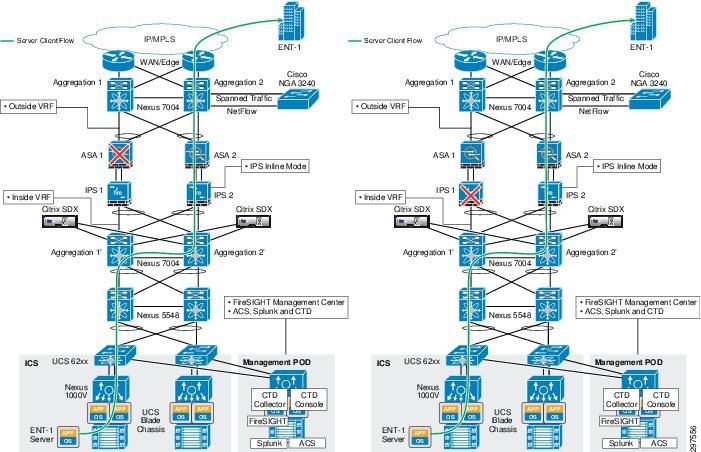
Figure 3-25 Traffic Flows with Various Link Failure
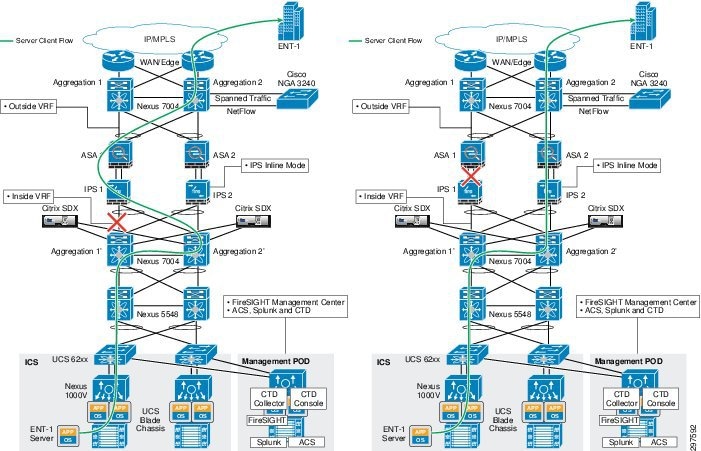
In ASA, link failure detection is based on the weighted average of the number of links. In this configuration, ASA has three links: two data links and one management link. For example, if the weight is set at 50%, at least two links must fail before the ASA firewall appliance can declare the failure, and the aggregation switch eventually reroutes traffic to the secondary path. NGIPS in the secondary path starts picking up new flows in the middle that were dropped from the primary NGIPS. The secondary NGIPS does not drop any flow it captures in the middle, but waits for more packets. If the flows were long-lived and the secondary NGIPS receives more packets, it will build the flows.
If only one physical link failed, either the data or management, there is no traffic rerouting.
Note![]() If only the ASA management link fails, traffic is not rerouted and the SP must fix the link failure. Otherwise, the management capability of the appliance is lost for the duration of failure.
If only the ASA management link fails, traffic is not rerouted and the SP must fix the link failure. Otherwise, the management capability of the appliance is lost for the duration of failure.
Note![]() Performance of the secondary NGIPS may be impacted if a huge number of long-lived flows were dropped because of primary NGIPS failure.
Performance of the secondary NGIPS may be impacted if a huge number of long-lived flows were dropped because of primary NGIPS failure.
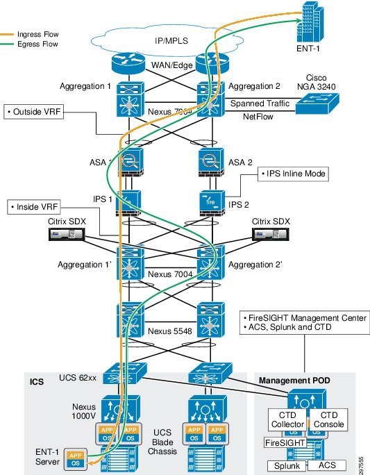
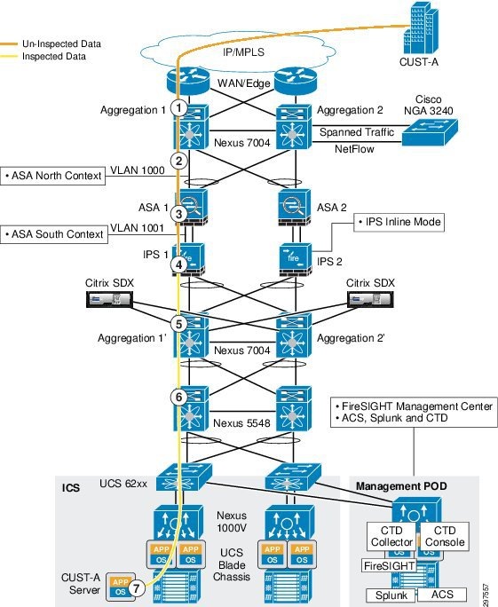
In the following traffic flow example, links between ASA and Nexus 7004 aggregation switches are configured as vPC links, so any such link failure does not impact the traffic flow. If a complete vPC failure, or a failure of any appliance occurs, traffic is rerouted to the secondary path.
1.![]() Packet arrives from the WAN cloud to N7K Agg-1 and is mapped to customer-specific VLAN 1000 (CUST-A-OUTSIDE)
Packet arrives from the WAN cloud to N7K Agg-1 and is mapped to customer-specific VLAN 1000 (CUST-A-OUTSIDE)
2.![]() Packet destined for the server is sent across the trunk on VLAN CUST-A-OUTSIDE to the ASA-1 context north (outside) interface and ASA applies the firewall policy
Packet destined for the server is sent across the trunk on VLAN CUST-A-OUTSIDE to the ASA-1 context north (outside) interface and ASA applies the firewall policy
3.![]() ASA-1 forwards the packet to N7K Agg-1′ on the south (inside) interface on customer VLAN 1001 (CUST-A-INSIDE)
ASA-1 forwards the packet to N7K Agg-1′ on the south (inside) interface on customer VLAN 1001 (CUST-A-INSIDE)
4.![]() When the packet is forwarded to N7K Agg-1′, NGIPS picks up the flow based on the VLAN tag and inspects the packets based on the configured policy before the packet reaches N7K Agg-1′
When the packet is forwarded to N7K Agg-1′, NGIPS picks up the flow based on the VLAN tag and inspects the packets based on the configured policy before the packet reaches N7K Agg-1′
5.![]() After being scanned by NGIPS, the packet continues to N7K Agg-1′ with VLAN tag of 1001 (CUST-A-INSIDE)
After being scanned by NGIPS, the packet continues to N7K Agg-1′ with VLAN tag of 1001 (CUST-A-INSIDE)
6.![]() N7K Agg-1’ routes the inspected packet on the Server-VLAN to the server over the trunk to N5K Access-1
N7K Agg-1’ routes the inspected packet on the Server-VLAN to the server over the trunk to N5K Access-1
7.![]() Packet reaches CUST-A server in the virtual environment
Packet reaches CUST-A server in the virtual environment
Figure 3-26 shows the traffic flow example.
Figure 3-26 Traffic Flow Example
In this design, physical links from Nexus 7004 aggregation nodes connect to ASA on the outside interface using the port channel. From ASA, the physical links on the inside interface physically connect to NGIPS; from NGIPS, these links are carried out to the Nexus 7004 aggregation nodes on the inside interface to complete vPC connectivity between ASA and Nexus 7004 aggregation nodes.
The NGIPS that is physically between the firewall and aggregation switch is deployed in transparent mode (bump in the wire).
The NGIPS physical port configuration follows:
1.![]() Physical Ports 1 – 2 are paired
Physical Ports 1 – 2 are paired
2.![]() Physical Ports 3 – 4 are paired
Physical Ports 3 – 4 are paired
3.![]() Physical Port 1 of IPS-1 connects to the northbound ASA -1 first link
Physical Port 1 of IPS-1 connects to the northbound ASA -1 first link
4.![]() Physical Port 2 of IPS-1 connects to Agg1′ switch
Physical Port 2 of IPS-1 connects to Agg1′ switch
5.![]() Physical Port 3 of IPS-1 connects to the northbound ASA-1 second link
Physical Port 3 of IPS-1 connects to the northbound ASA-1 second link
6.![]() Physical Port 4 of IPS-1 connects to the Agg2′ switch
Physical Port 4 of IPS-1 connects to the Agg2′ switch
For example, if port 2 on IPS-1 is down, or the link between port 2 and Agg1′ is down, IPS-1 propagates link failure to port 1 so that ASA knows the first link is down and route traffic to the second link. Similarly, if port 1 is down, IPS-1 propagates the down status toward port 2 so that the Nexus 7004 knows that port is down and routes traffic to Agg2′, which in turn routes the traffic back to the IPS-1 on port 4 (IPS-1 physical port).
When tenant traffic comes into the data center and sent to the FW outside interface the ASA firewall marks the traffic with the associated inside VLAN tag. When the traffic passes through NGIPS, it inspects tenant traffic based on the defined VLAN policies.
As shown in Figure 3-27, IPS-1 and IPS-2 are deployed with identical configurations to support HA. In this mode, FireSIGHT Management Center deploys all configurations on both NGIPS. The SP can configure both NGIPS IP addresses in FireSIGHT Management Center, so whenever new configurations or changes are made, FireSIGHT Management Center downloads the same configurations on both NGIPS. During a failure event, either one of the NGIPS can support the tenants and be able to inspect based on the original policies configured.
Figure 3-27 FireSIGHT Management Center Policies Tab
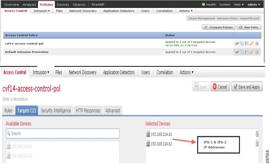
As shown in Figure 3-27, after creating a policy or after making a change, the user can assign this to one or more devices (NGIPS). The VMDC Cloud Security 1.0 reference architecture specifies two NGIPS; both were added so that changes and new configurations are downloaded to both.
When deploying a single IPS appliance in fail closed mode between the aggregation and access layer, NGIPS appliance failure splits the data center and causes a major data center outage. Deploying multiple NGIPS between the aggregation and access layers supports multiple link failures and a single IPS appliance failure.
Inserting a Single NGIPS at the Aggregation Layer
As shown in Figure 3-28, an NGIPS can be inserted between the aggregation and access layer as a single physical appliance.
Figure 3-28 Inserting a Single NGIPS between the Aggregation and Access Layers

Table 3-6 summarizes the pros and cons of this deployment model.
|
|
|
|---|---|
Higher Scale than at the access layer. (Required fewer appliances with higher performance) |
|
Overall Scale and Performance limited by physical interfaces |
|
Deploying a single IPS appliance between the aggregation and access layer resolves the asymmetrical traffic issue as shown in Figure 3-29.
Figure 3-29 Deployment Model Traffic Flows
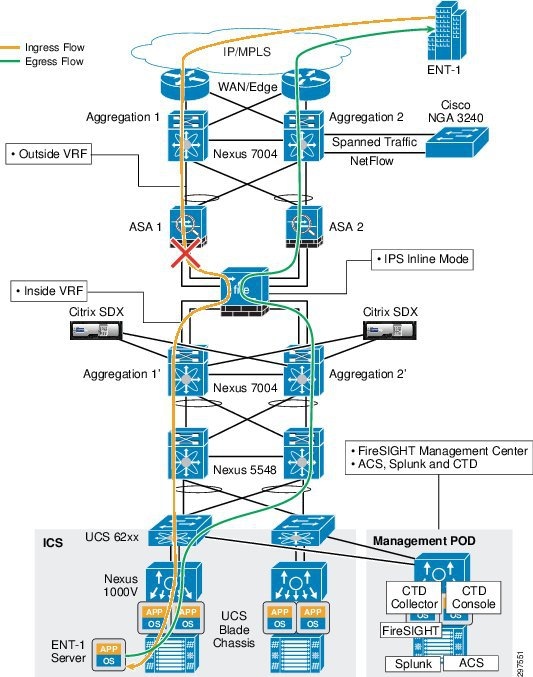
When traffic flows from outside to inside, it may go through the aggregation switch Agg-1, then pass transparently through NGIPS to access switch 1 and so on towards the server or specific application. On the return path, traffic may go through access switch 2 and then NGIPS and if there is a link failure between ASA-1 and NGIPS, the return traffic goes to ASA-2 to Agg-2 and does not cause any asymmetrical traffic flow issue. This is because there is only one NGIPS appliance between the aggregation and access layers, hence traffic flows from north to south and south to north go through the same NGIPS appliance and there is no asymmetrical flow issue.
Similarly as shown in Figure 3-30 there is no asymmetrical traffic flow issue through NGIPS even if an ASA firewall or aggregation switch goes down.
Figure 3-30 Firewall or Aggregation Switch Failure
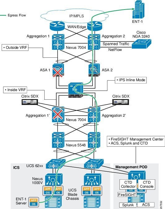
In this deployment model, NGIPS is deployed in fail closed mode, so if the appliance hardware fails, no traffic passes through the appliance. There is no HA when deploying a single appliance. Because NGIPS sits inline physically between the aggregation and access layers, an NGIPS hardware failure causes a major outage and north-south traffic is completely disconnected, causing a major disaster in the data center. This design can sustain a single link failure, but failure of the appliance hardware causes a complete loss of cloud services, as shown in Figure 3-31. This splits the data center and all services are down until the NGIPS appliance recovers.
Figure 3-31 NGIPS Appliance Failure
Note![]() Recommendation is to inspect traffic at all times, hence fail open mode is not tested in this release.
Recommendation is to inspect traffic at all times, hence fail open mode is not tested in this release.
On the other hand, if a single NGIPS is deployed in a fail open mode, hardware failure of the appliance may not cause a complete data center disaster as shown in Figure 3-32.
However in fail open mode the cloud services may not get impacted, but NGIPS passes traffic without any inspection which may impose security threat to the entire data center.
Figure 3-32 Appliance Failure in Fail Open Mode
Note![]() Designs in which a single component failure causes a major outage are never recommended, especially in multi-tenant environments. In multi-tenant environments, the architecture should be able to sustain any single component failure or multiple link failures in the data center.
Designs in which a single component failure causes a major outage are never recommended, especially in multi-tenant environments. In multi-tenant environments, the architecture should be able to sustain any single component failure or multiple link failures in the data center.
Inserting NGIPS at the Access Layer
NGIPS can be inserted at the access layer as shown in Figure 3-33:
Figure 3-33 Inserting NGIPS at the Access Layer
NGIPS is deployed in transparent mode, as a bump in the wire, and is in active or inline mode. In this design, NGIPS is deployed at the access layer, or between Nexus 5000 access switches and Fabric Interconnect.
Table 3-7 summarizes the pros and cons of this deployment model.
|
|
|
|---|---|
Not Scalable. Require a pair of NGIPS per Compute Pod (Vblock or FlexPod) |
|
Figure 3-34 shows the ingress and egress data flows.
Figure 3-34 Ingress and Egress Data Flows
As shown in Figure 3-34, ingress traffic gets to the server through aggregation 1 and access switch 1 and fabric interconnect 1 to the respective server. The return path from server depends upon the hashing algorithm of UCS – FI, which may return the traffic to either N5K-1 or N5K-2.
Due to this internal hashing mechanism of UCS-FI, egress traffic may get to N5K-2 through IPS 2. This creates an asymmetrical traffic flow in which some incoming packets may flow on one side and some incoming packets may flow on the other side. In the preceding example, incoming traffic passes through IPS-1, which picks up the flow, but on the return path egress traffic flows through IPS-2.
This design can sustain a single NGIPS appliance failure and multiple vPC link failures. If an NGIPS appliance fails, traffic is directed to the second IPS-2, which tries to pick up the traffic at mid-flow. If the flow is long enough, NGIPS builds the flow using the next few packets. If flows are short-lived, the original flows which were active on IPS-1 are lost. This happens for only a very short period before new flows are captured by the second IPS-2.
Inserting NGIPS at the Data Center Edge
Figure 3-35 shows the placement of multiple NGIPS between the data center edge or WAN edge and data center aggregation layer.
Figure 3-35 Inserting NGIPS between the Data Center Edge and Data Center Aggregation Switches
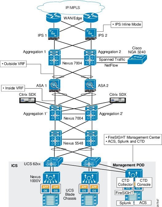
Table 3-8 summarizes the pros and cons of this deployment model.
|
|
|
|---|---|
When deploying NGIPS between the data center edge and the data center aggregation layer, all traffic goes through NGIPS.
In this design, NGIPS captures all the traffic coming into the data center, so NGIPS also processes some unwanted traffic. For example, if unauthorized users or devices try to access the data center, NGIPS inspects their traffic, too, and wastes processing power and may create false alarms. On the other hand, if NGIPS is deployed behind the data center firewall, it does not see unauthorized user or device traffic and so uses less processing power.
This design can sustain a single NGIPS failure. Traffic fails over to the secondary NGIPS with minimal disruption as shown in Figure 3-36 and Figure 3-37.
Figure 3-36 Ingress Traffic Flow
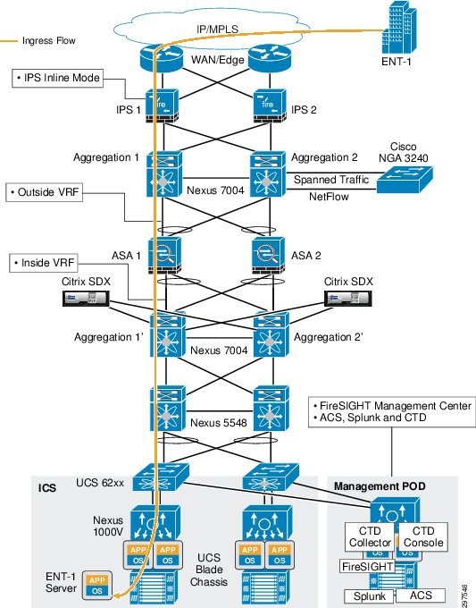
Figure 3-37 Egress Traffic Flow
Deploying the Management Network
The management network can be deployed by using an out-of-band (OOB) access to manage devices in the data center. To accomplish OOB, dedicated management ports are connected to a dedicated OOB network that hosts management and monitoring services. This section describes the general outline and best practices for deploying a management network. Details of the deployment of the management network used in this solution will be provided in the implementation guide.
The OOB network segment hosts console servers, network management stations, authentication, authorization, accounting (AAA) servers, analysis and correlation tools, Network Time Protocol (NTP), File Transfer Protocol (FTP), Syslog servers, network compliance management, and any other management and control services.
The management network deployment should use the following best practices:
- Provide isolation of the OOB network from the network infrastructure
- Enforce access control of all managed devices
- Separate different types on management traffic into separate subnets
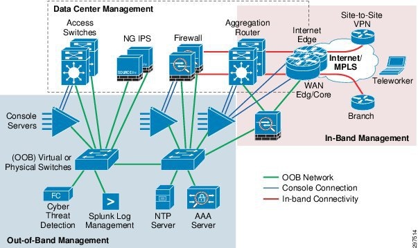
In the OOB infrastructure, using dedicated switches, firewalls, and VLAN subnets implements separation between data and management networks,.These dedicated appliances are in addition of the network infrastructure described within the VMDC architecture. Optionally as shown, one can allow for in-band (IB) management of Internet facing devices, where management access is achieved by using links used for user data flows. The logical topology of the management network is shown in Figure 3-38.
Figure 3-38 Data and Management Network Separation
Management Network Considerations
The management plane carries NetFlow traffic, along with NetFlow Secure Event Logging (NSEL) traffic between Adaptive Security Appliance (ASA) and NetFlow Generation Appliance (NGA) appliance and the Cisco Cyber Threat Defense (CTD) collector. It is a best practice to keep management traffic on a separate subnet, and we recommend using a separate subnet for management traffic for the physical appliances.
When deploying switches and firewalls in the OOB network, consider the following:
- The OOB components such as AAA servers, or log management systems can be either physical appliances or virtual machines. If virtual machines (VMs) host Cisco CTD or Splunk applications, one can leverage Nexus1000V to provide connectivity to the OOB network. One must use separate VLANs and port profile configurations in Nexus 1000V virtual switches to achieve management separation for management VLANs from the rest of the network.
- If In-band management connectivity is configured for core or aggregation routers, you must separate management ports using a firewall to reduce the risk of unauthorized access to the entire management domain.
- Authenticate and authorize access to devices using AAA.
- Use HTTPS and SSH for device access.
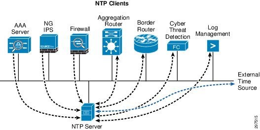
Deploying Network Time Protocol Services in the Management Network
Time synchronization using NTP for network and security devices is critical for threat correlation, event analysis, and log management. NTP traffic also uses the OOB management network to communicate with time servers.
When deploying NTP in the OOB management network, consider the following:
- Deploy a hierarchical NTP design rather than a flat design. Within this framework, all devices within the data center are synced with a local NTP server, and that server is then synced to an external time-source. Hierarchical designs are preferred because they are highly stable, scalable, and provide the most consistency.
- Use a common time zone throughout the infrastructure to facilitate event analysis and correlation.
- Control which clients and peers can talk to an NTP server.
- Enable NTP authentication.
In this design, routers and switches can be configured as clients having a client/server relationship with internal time servers in the OOB management network. The internal time servers are synchronized with external time sources as shown in Figure 3-39.
Figure 3-39 Time Server Synchronization with External Time Source
Authentication and Role-Based Access Control
Network infrastructure devices often provide a range of different access mechanisms, including console and asynchronous connections, as well as remote access based on protocols such as Telnet, rlogin, HTTP, and SSH. Some mechanisms are typically enabled by default with minimal security associated with them; for example, Cisco IOS software-based platforms are shipped with console and modem access that is enabled by default. For this reason, each infrastructure device should be carefully reviewed and configured to ensure only supported access mechanisms are enabled and that they are properly secured. The key measures to securing both interactive and management access to an infrastructure device are as follows:
–![]() Limit the accessible ports and restrict the permitted communicators and the permitted methods of access.
Limit the accessible ports and restrict the permitted communicators and the permitted methods of access.
–![]() Display legal notice developed in conjunction with company legal counsel for interactive sessions.
Display legal notice developed in conjunction with company legal counsel for interactive sessions.
–![]() Ensure access is only granted to authenticated users, groups, and services.
Ensure access is only granted to authenticated users, groups, and services.
–![]() Restrict the actions and views permitted by any particular user, group, or service.
Restrict the actions and views permitted by any particular user, group, or service.
–![]() Protect locally stored sensitive data from viewing and copying.
Protect locally stored sensitive data from viewing and copying.
–![]() Record who accessed the device, what occurred, and when for auditing purposes. Implementing Authentication, Authorization and Accounting (AAA). AAA is an architectural framework for configuring the following set of independent security functions in a consistent, modular manner:
Record who accessed the device, what occurred, and when for auditing purposes. Implementing Authentication, Authorization and Accounting (AAA). AAA is an architectural framework for configuring the following set of independent security functions in a consistent, modular manner:
Authentication—Enables users to be identified and verified prior to them being granted access to the network and network services.
Authorization—Defines the access privileges and restrictions to be enforced for an authenticated user.
Accounting—Provides the ability to track user access, including user identities, start and stop times, executed commands (such as command-line interface (CLI) commands), number of packets, and number of bytes.
In this solution Cisco Access Control System (ACS) in conjunction with Active Directory is leveraged to implement password protection, Role Based Access and AAA services. In addition ACS provides detailed reports on events such as: who accessed a network and when; who failed to access which devices; what command did they execute; details on device configuration changes. Detailed reports on these events as well as secure auditing, is required for regulatory and compliance efforts. More information on deploying and managing ACS access policies and identity roles can be found at:
http://www.cisco.com/c/en/us/td/docs/net_mgmt/cisco_secure_access_control_system/5-5/user/guide/acsuserguide/introd.html
In addition to the existing network infrastructure devices; the newly introduced FirePOWER and Cyber Threat Defense security appliances offer a number of configuration options to implement access control.
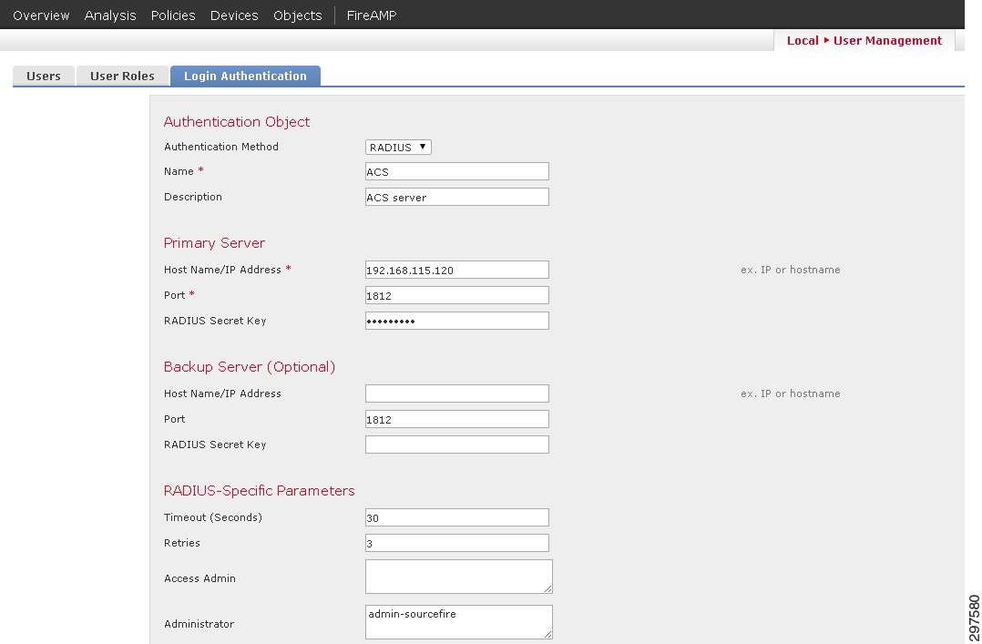
FirePOWER authentication is performed through active directory. Configuration can be done under “System/User-Management” pane, where users, user-roles and login authentication parameters can be set. Various predefined user roles are available and can be assigned to different users. FirePOWER can point to the ACS server for authentication under the login-authentication page as shown in Figure 3-40.
Figure 3-40 Login-Authentication Page
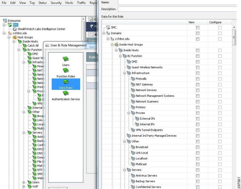
In Cisco CTD, the user can set management parameters under the configuration/user management pane including setting up other users, functional roles and authentication service. Similar to the FirePOWER appliance, there are predefined functional roles that can be leveraged, such as Configuration Manager, or Security Analysts. Custom-made roles can also be configured. These functional roles define what information can be viewed. In addition the data roles define what parameters can be viewed as well as configured. Figure 3-41 shows the data role configuration screen within the Cisco CTD's SMC console, where custom-made roles can be configured
Figure 3-41 Data Role Configuration Screen
Integrating Cisco Cyber Threat Defense
Cisco Cyber Threat Defense (CTD) uses network device telemetry to provide deep, complete visibility across the network core, enabling security operators to understand and use network traffic details to discover anomalies. Deploying Cisco CTD across networks can provide information and visibility to support security operators in a variety of threat detection tasks, including:
- Data loss detection
- Network reconnaissance of internal networks
- Monitoring the spread of malware in internal networks
- Botnet command and control channel detection in internal networks
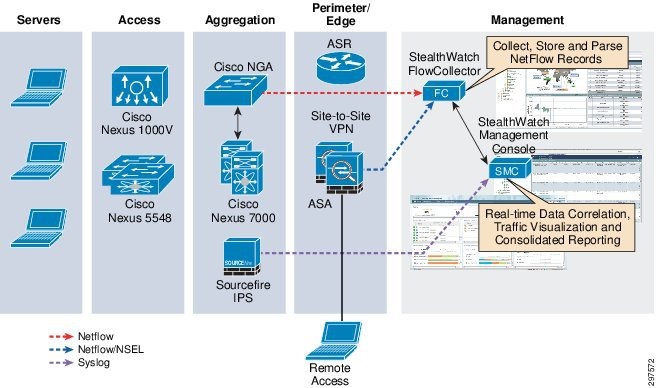
Figure 3-42 shows the main components of Cisco CTD.
Figure 3-42 Cisco CTD Solution Components
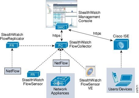
In this solution, the Cisco CTD component are:
- FlowCollector—A virtual appliance that aggregates and normalizes NetFlow and application-type data collected from Cisco Nexus Series switches, Cisco Adaptive Security Appliance (ASA) firewalls, and Cisco NetFlow Generation Appliance (NGA)
- StealthWatch Management Console (SMC)—A virtual appliance that aggregates, organizes, and presents FlowConnector analyses using graphical representations of network traffic, customized summary reports, and integrated security and network intelligence for drill-down analysis
Note![]() Other Cisco CTD components shown in Figure 3-42, such as FlowSensor, are optional and are not deployed in this version of this solution.
Other Cisco CTD components shown in Figure 3-42, such as FlowSensor, are optional and are not deployed in this version of this solution.
Architecture
Cisco CTD uses network traffic telemetry from ASA 5585-X Series Next Generation Firewalls and NGA, which converts raw traffic spanned from Nexus 7000 Series switches to NetFlow records. These appliances export NetFlow records to FlowCollector, which forwards them to SMC. SMC provides centralized management for all netflow-enabled appliances, and provides real-time data correlation, visualization, and consolidated reporting.
Figure 3-43 shows the high-level Cisco CTD system architecture.
Figure 3-43 FCTD System Architecture
Cisco CTD can be configured to translate Syslog messages from FirePOWER generated by Intrusion events in its database and reporting structure.
Deploying Exporters
The ASA implementation of NetFlow, called NetFlow Security Event Logging (NSEL), enables specific high-volume traffic events to be exported from the security appliance more efficiently and in a more scalable way than standard Syslog logging. NSEL can be configured in separate contexts on ASA to support per-tenant visibility. After Cisco CTD receives NSEL records from each ASA context, Cisco CTD populates multiple contexts in its exporter-tree database. Exporters can also be manually configured using a Cisco CTD configuration menu.
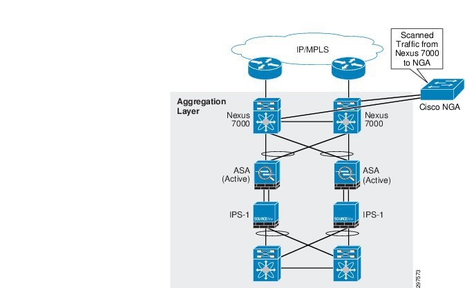
In large data centers, generating NetFlow at high rates can be challenging. To address this, NGA converts raw high-rate data traffic that is spanned from Nexus 7000 Series switches, and converts it to NetFlow Version 9 traffic. NGA has four 10 Gigabit Ethernet (10 GbE) monitoring interfaces and up to four independent flow caches and flow monitors. Two 10 GbE ports are used to receive Nexus 7000 data. Strategically placing the NGA in the aggregation layer provides effective traffic monitoring in the data center, and provide additional statistics for traffic leaving the data center. Figure 3-44 shows the NGA deployment.
When deploying NGA and ASA to export NetFlow data, NSEL and NetFlow Version-9 does not export identical object fields. Understanding what each device exports helps to develop end-to-end strategies for obtaining a complete network visibility. This is described in more detail in Event Correlation and Data Analysis.
Note![]() The following documents describe the fields supported in NSEL and NGA and further information on various deployment options and performance of NGA.
The following documents describe the fields supported in NSEL and NGA and further information on various deployment options and performance of NGA.
- http://www.cisco.com/c/en/us/td/docs/security/asa/asa90/system/netflow/netflow.pdf
- http://www.cisco.com/c/dam/en/us/solutions/collateral/borderless-networks/threat-defense/cyber_threat_defense_design_guide.pdf
- http://www.cisco.com/c/en/us/products/collateral/cloud-systems-management/netflow-generation-3000-series-appliances/white_paper_c11-708294.html
Deploying StealthWatch FlowCollectors
StealthWatch FlowCollectors deployments can be distributed or centralized. In distributed deployments, FlowCollectors are deployed at multiple locations and are usually placed close to the source producing the highest number of NetFlow records. In a multi-tenant environment, we recommend the following best practices:
- Separate FlowCollectors can be used for tenants having overlapping IP addresses. Each FlowCollector should be placed in a separate domain in the SMC domain tree. This enables separation and simplifies data analysis for tenants that use overlapping IP addresses. Tenant-specific NetFlow records are configured and exported in each ASA context.
- Multiple tenants can export NetFlow data to the same collector. In this scenario, ensure that the total number of exported flows do not exceed FlowCollector capacity.
- Use a separate FlowCollector to collect NetFlow records from NGA. Because NGA exports aggregated traffic from all tenants, ensure that this FlowCollector has sufficient capacity to collect state data on all conversations without purging active records before reaching the idle-time threshold.
- When firewalls are deployed in the management network, appropriate ports and services must be enables to ensure correct communication and operation of the various Cisco CTD components. Table 3-9 summarizes the required services:
|
|
|
|
|
|---|---|---|---|
For more detailed information about required services, refer to http://www.cisco.com/c/dam/en/us/solutions/collateral/borderless-networks/threat-defense/cyber_threat_defense_design_guide.pdf.
These recommendations limit NetFlow overhead and provide per-tenant visibility even if tenants use overlapping IP addresses. This deployment model can support the use separate FlowCollectors for high-end network container types, and another FlowCollector to aggregate NetFlow records from multiple lower-end tenants.
Performance is another important design consideration. The following important factors should be considered:
- Exporter Count—the number of exporting devices that each FlowCollector can accept.
- Data Rate—the flows per second (fps) rate that the FlowCollector receives.
- Host Count—the number of hosts inside and outside the network for which the FlowCollector can maintain state. We recommend that the number of inside hosts not exceed 60% of the host count value.
- Flow Storage—the amount of granular flow data storage required for a particular network location.
Traffic throughput (Gigabit per second, or Gbps) has no direct bearing on exported fps; the only measure that directly impacts throughput is the number and rate of flows passing through a device. For example, a high-volume (1 Gbps) flow could pass through a port, resulting in an fps less than one. In contrast, many small-volume flows could pass through a port, resulting in low total throughput but high fps (4000 fps with a total throughput of 100 Mbps, for example).
Table 3-10 summarizes the FlowCollector VE system requirements:
For more information in about performance design considerations, refer to http://www.cisco.com/c/dam/en/us/solutions/collateral/borderless-networks/threat-defense/cyber_threat_defense_design_guide.pdf .
 Feedback