Configuring ACI In-Band Management for Hardware Flow Telemetry Export
This document provides procedures for configuring Cisco ACI in-band management for Cisco Tetration hardware sensors.
Prerequisites for Configuring Cisco ACI In-Band Management for Hardware Flow Telemetry Export
These are the prerequisites for configuring Cisco Application Centric Infrastructure (ACI) in-band management for hardware flow telemetry.
Supported Hardware and Software
For supported ACI hardware switches, ACI software version and Tetration software version refer to the Tetration platform datasheet https://www.cisco.com/c/en/us/products/collateral/data-center-analytics/tetration-analytics/datasheet-c78-737256.html
Required inb VRF Under mgmt Tenant
You must use the inb VRF under the mgmt tenant because it is hardcoded in the Hardware Agent.
-
In your Cisco APIC system, navigate to the bridge domain page under the mgmt tenant:
-
On the Bridge Domain - inb page, click the Policy tab.
The General subtab under the Policy tab should be selected automatically.
-
Locate the VRF field and verify that the inb VRF is selected for the mgmt tenant.
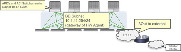
Required Use of Bridge Domain Subnet as Gateway for Hardware Agent For Spine Hardware Sensor
For the spine hardware sensor only, you must use the bridge domain subnet as the gateway for the Hardware Agent, which means that you will also need an L3Out to reach the telemetry collector. This is because the spine switch doesn?t apply the ARP for the node in-band management IP address.
The following figure shows an example of this configuration.
In-Band or Out-of-Band Considerations
-
If you use both out-of-band and in-band for external connections, in-band is preferred for packets sourced from the APIC by default (for example, VMM integration).
-
Cisco APIC uses the following forwarding logic:
-
Packets that come in from an interface go out from that same interface
-
Packets sourced from a Cisco APIC that are destined to a directly connected network go out from the directly connected interface
-
Packets sourced from a Cisco APIC that are destined to a remote network prefer in-band primarily, followed by out-of-band
-
-
If you prefer to use out-of-band for external connections, navigate to:
Then select ooband in the Interface to use for external connections field.
Configure the Pod Policy
Before you can configure in-band management, you must first configure the pod policy. Configuring the pod policy consists of these tasks:
-
Configuring the BGP route reflector
-
Configuring NTP
-
Enabling HTTP on the Cisco APIC
Procedure
| Step 1 |
Determine which pod policy group is being used by your APIC system. |
| Step 2 |
Locate the BGP route reflector, Date and Time, and Management Access policies used by the pod policy group. |
| Step 3 |
Configure the BGP route reflector. The ACI fabric route reflectors use multiprotocol BGP (MP-BGP) to distribute external routes within the fabric. To enable route reflectors in the ACI fabric, the fabric administrator must select the spine switches that will be the route reflectors, and provide the autonomous system (AS) number. Once route reflectors are enabled in the ACI fabric, administrators can configure connectivity to external networks. |
| Step 4 |
Configure NTP. |
| Step 5 |
Enable HTTP. You must have HTTP enabled because the switches download the Hardware Agent from the APIC through HTTP. In the Cisco APIC 6.0(1) release and earlier: In the Cisco APIC 6.0(2) release and later: |
What to do next
Go to Configuring Cisco ACI In-Band Management for Hardware Flow Telemetry.
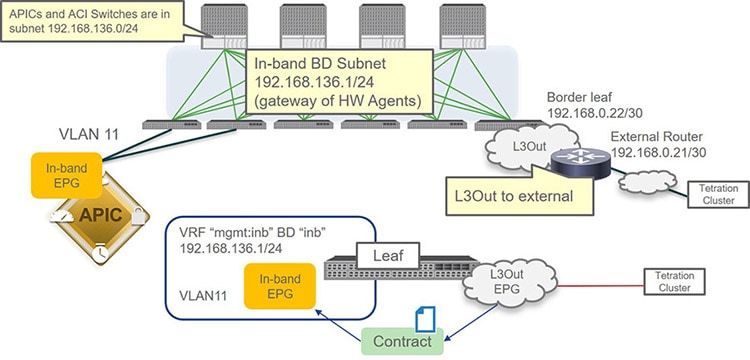
Configuring Cisco ACI In-Band Management for Hardware Flow Telemetry
The following topology is used as an example configuration for these procedures.
Before you begin
-
Verify that you have reviewed and followed the information provided in Prerequisites for Configuring Cisco ACI In-Band Management for Hardware Flow Telemetry Export.
-
Verify that the pod policy is configured correctly using the information provided in Configure the Pod Policy.
Procedure
| Step 1 |
Configure the VLAN pool. |
| Step 2 |
Configure the physical domain and AEP. |
| Step 3 |
Apply the access policy to the interface connecting to the Cisco APIC. |
| Step 4 |
Configure the in-band management EPG. |
| Step 5 |
Assign in-band management IP addresses to the leaf and spine switches. |
| Step 6 |
Assign in-band management IP addresses to the APICs. |
| Step 7 |
Configure the inb bridge domain subnet. |
| Step 8 |
Verify that the configurations have been completed successfully thus far. |
| Step 9 |
Configure the L3Out EPG. |
| Step 10 |
Create a contract between the L3Out EPG and the in-band management EPG. |
| Step 11 |
Configure the inb bridge domain for the L3Out. |
| Step 12 |
Verify that the switches can ping the telemetry collector IP address. |
| Step 13 |
From the telemetry collector, download the hardware agent (RPM).
|
| Step 14 |
Upload the hardware agent onto the APIC. |
| Step 15 |
Understand the upcoming steps on enabling leaf switches for analytics. Before going through the next few steps in these procedures, it s helpful to understand what you will be doing and why.
The following figure shows how the components that you will be configuring in the upcoming steps tie in with one another. 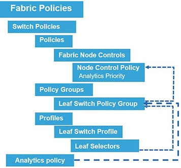
|
| Step 16 |
Configure the fabric node control policy. |
| Step 17 |
Create an analytics policy. |
| Step 18 |
Create a leaf and spine switch policy group. |
| Step 19 |
Create the leaf and spine switch profiles. |
| Step 20 |
Verify the configurations were set correctly. |
| Step 21 |
Verify the configuration. |
 Feedback