Cisco Video Surveillance Deployment Guide for the UCS Express Platform
Available Languages
Table Of Contents
Video Surveillance Deployment Guide for the UCS Express Platform
EtherSwitch Router Configuration
Onboard Ethernet Router Configuration
External Interface Router Configuration
Installing and Configuring the ISR Router and SRE
Verifying the IOS Image of the ISR
Verifying and Configuring the SRE Hypervisor
Deploying the VSM 6.3.2 Template
Configuring Network Switches for the VSM VM
Video Surveillance Deployment Guide for the UCS Express Platform
November 2012This guide describes the key requirements and instructions for deploying a virtualized Cisco® Video Surveillance Manager (VSM) on the Cisco Unified Computing System™ (UCS) Express platform.
Contents
This document includes the following sections:
Installing and Configuring the ISR Router and SRE
Deploying the VSM 6.3.2 Template
Configuring Network Switches for the VSM VM
Introduction
This guide describes the key requirements and instructions for deploying a virtualized Cisco VSM on the Cisco UCS Express platform. This guide describes installation and configuration guidelines for the Service Ready Engine (SRE) blade server, VMware vSphere Hypervisor, Integrated Service Router Generation 2 (ISR G2), and the VSM virtual machine (VM), as well as best practice recommendations.
Audience
This guide is intended for use by Cisco System Engineers, Physical Security Advanced Technology Provider (ATP) partners, and technical field staff who develop and implement Cisco Video Surveillance and UCS Express for branch office solutions.
A successful implementation also requires additional knowledge in the following areas:
•
Cisco ISR-G2 (29xx/39xx Series) Internetwork Operating System (IOS) router configuration
•
Scope
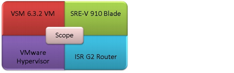
This guide contains detailed instructions on the installation of the VSM on UCS Express on the ISR G2 (Figure 1).
Figure 1 Deployment Guide Scope

Note
Note
System Overview
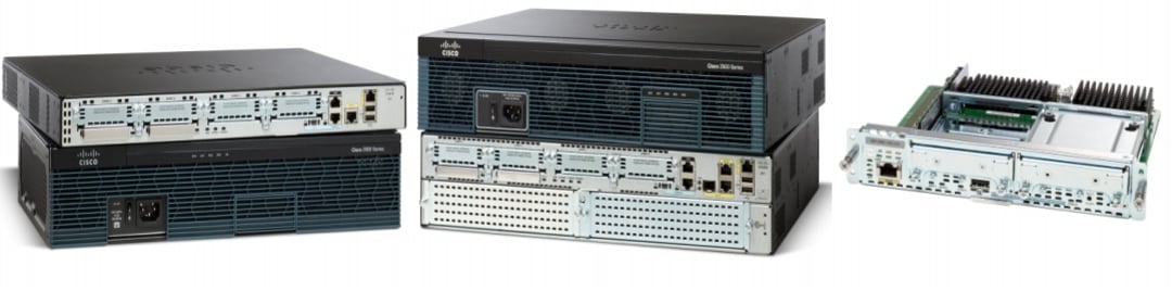
The Cisco UCS Express product is an SRE blade on an ISR G2 branch office router running the SRE-V (ESXi) virtualization software. The 2900 and 3900 series routers have various Gigabit Ethernet interfaces onboard, wide-area network (WAN) interface card (WIC) interface slots, and multiple service module slots, depending on the model (Figure 2).
Figure 2 Cisco Integrated Service Routers and Service Ready Engine
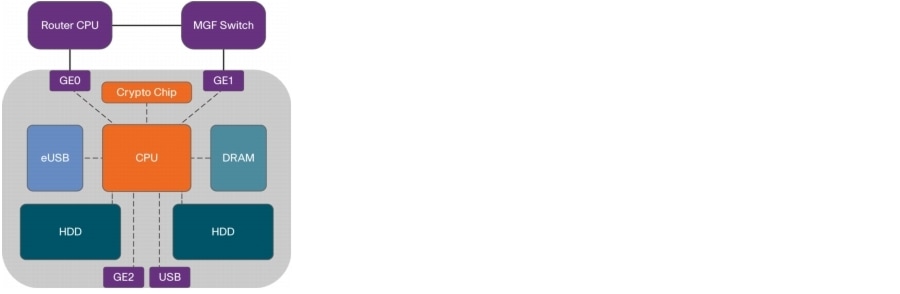
The SRE 910 blade is inserted into one of the service module slots. Figure 3 displays that there are two Gigabit Ethernet internal interfaces on the router: one connected to the router and the second connected to MultiGigabit Fabric (MGF). There is also one external Gigabit Ethernet interface on the front panel of the SRE. The SRE blade has two 500 GB hard drives and 4 GB of random-access memory (RAM).
Figure 3 SRE Hardware Architecture
EtherSwitch Router Configuration
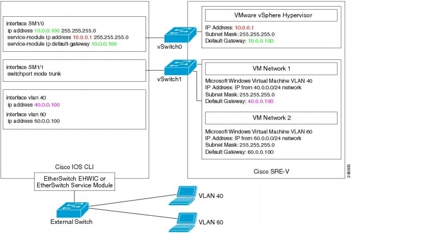
The specific router configuration depends on which interface is being used to connect to the external switch. In the first recommended deployment configuration (Figure 4), the EtherSwitch Enhanced High-speed WAN interface card (EHWIC) or EtherSwitch Service Module is used to connect to the external switch (Figure 5).
Figure 4 Host Router Connected to External Switch via MGF and EtherSwitch
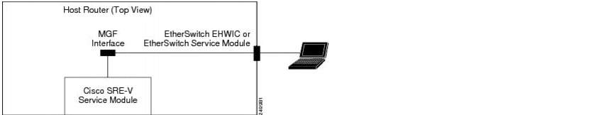
Figure 5 Router Configuration Sample and Topology for External Switch via MGF and EtherSwitch
Note
Onboard Ethernet Router Configuration
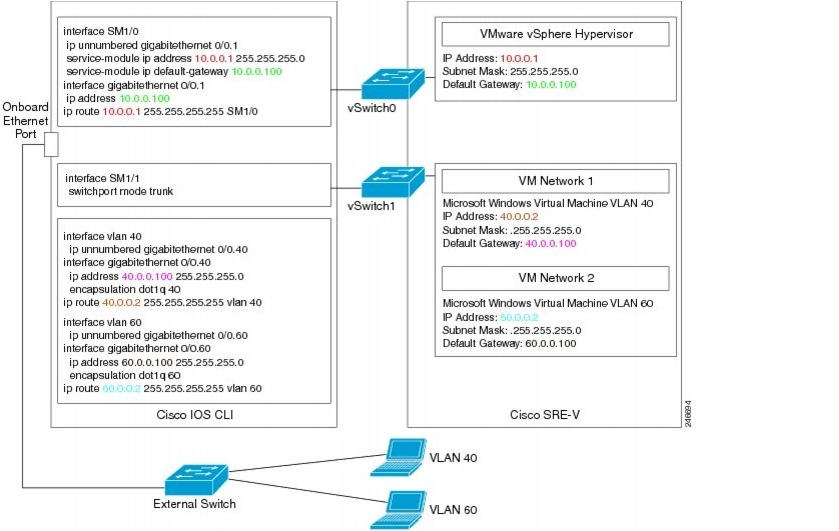
In the second possible deployment configuration (Figure 6), the router's onboard Ethernet port is used to connect to the external switch (Figure 7).
Figure 6 Host Router Connected to an External Switch via an Onboard Router Port

Figure 7 Router Configuration Sample and Topology for External Switch via Onboard Port
External Interface Router Configuration
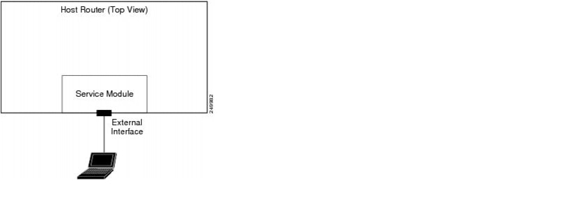
In the third potential deployment configuration (Figure 8), the external interface on the front panel of the UCS Express Service Module is used to connect to the external switch.
Figure 8 Host Router for External Switch via Front Panel Service Module Interface
This option has some limitations:
•
•
More details can be found in the Installation and Configuration Guide for Cisco Services Ready Engine Virtualization, Release 2.0 at http://www.cisco.com/en/US/docs/interfaces_modules/services_modules/sre_v/2.0/user/guide/overview.html.
Logical Network Topology
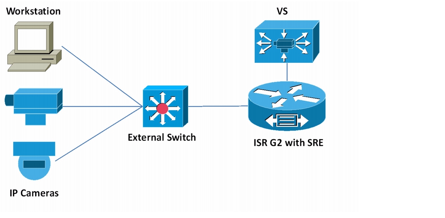
Figure 9 illustrates the overall logical topology of the networking and video surveillance components, including a UCS Express containing the SRE-V running VSM, the Video Surveillance Operations Manager (VSOM), various IP cameras, an external switch, and the operator workstations running the VSOM client.
Figure 9 Logical Network Topology

Caution
Installing and Configuring the ISR Router and SRE
This guide describes the installation steps of configuring the ISR router and SRE, setting up the network interfaces, configuring hypervisor services and guest clients, and deploying and verifying the VSM VM.
Note
•
•
•
•
Verifying the IOS Image of the ISR
To verify the IOS image of the ISR:
Step 1
Step 2
If the router is running a version older than 15.1(4)M, then download and upgrade the IOS image to the correct version. To learn how to upgrade an IOS image, navigate to the Cisco web site at http://www.cisco.com/en/US/docs/net_mgmt/configuration_engine/3.0/administration/guide/upgrade.html.
Configuring the ISR Interface
To configure the ISR interface:
Step 1
This command displays two interfaces, SM 1/0 and SM 1/1, assuming that the SRE blade is plugged into Service Module Slot 1. SM 1/0 is connected to the vSwitch0 vmKernel port of the Hypervisor, and SM 1/1 is connected to the vSwitch0 VM port group.
Step 2
interface GigabitEthernet0/0description $ETH-LAN$$ETH-SW-LAUNCH$$INTF-INFO-GE 0/0$ip address 10.10.1.151 255.255.255.0interface SM1/0ip unnumbered GigabitEthernet0/0service-module ip address 10.10.1.152 255.255.255.0service-module ip default-gateway 10.10.1.151
Configuring the ISR VLANs
To configure the ISR VLANs:
Step 1
interface SM1/1description Internal switch interface connected to Service Moduleswitchport mode trunkStep 2
interface GigabitEthernet0/1.60encapsulation dot1Q 60ip address 10.3.8.3 255.255.248.0vlan 60interface Vlan60description VSM VLANip unnumbered GigabitEthernet0/1.60Step 3
ip route 10.10.1.152 255.255.255.255 SM1/0ip route 10.3.8.5 255.255.255.255 Vlan60
Verifying and Configuring the SRE Hypervisor
To verify and configure the SRE hypervisor:
Step 1
Step 2
service-module sm 1/0 sessionStep 3
Figure 10 Hypervisor User Interface Screen
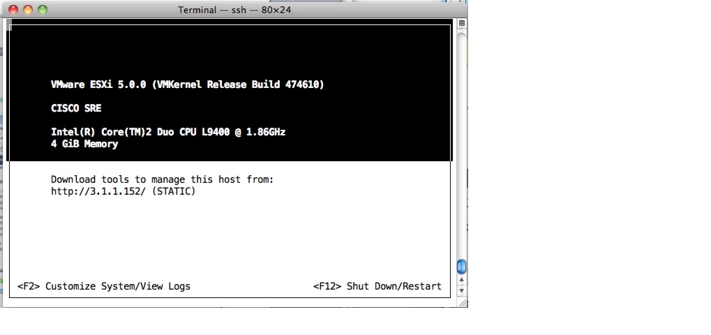
Step 4
Step 5
Step 6
Step 7
Step 8
•
•
service-module sm 1/0 session clear
Note
Installing the vSphere Client
To install the vSphere client:
Step 1
Step 2
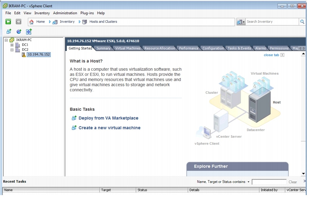
Note
Figure 11 vSphere Client Main Screen
Deploying the VSM 6.3.2 Template
To deploy the VSM 6.3.2 template:
Step 1
Step 2
Note
Step 3
Step 4
Figure 12 Launching the Deploy OVF Template Wizard in the vSphere Client
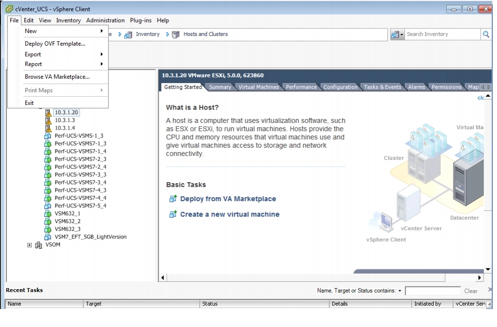
Step 5
a.
b.
c.
d.
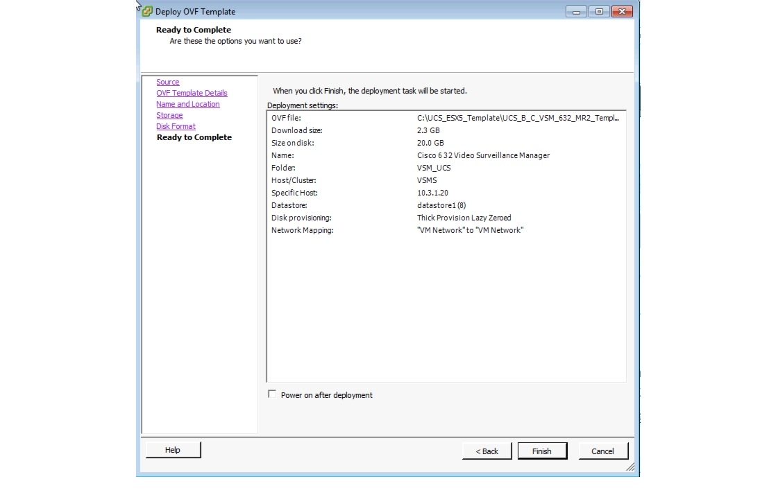
Figure 13 displays the result of those selected deployment settings.
Figure 13 Ready to Complete the OVF Wizard —VSM Template and Default Settings
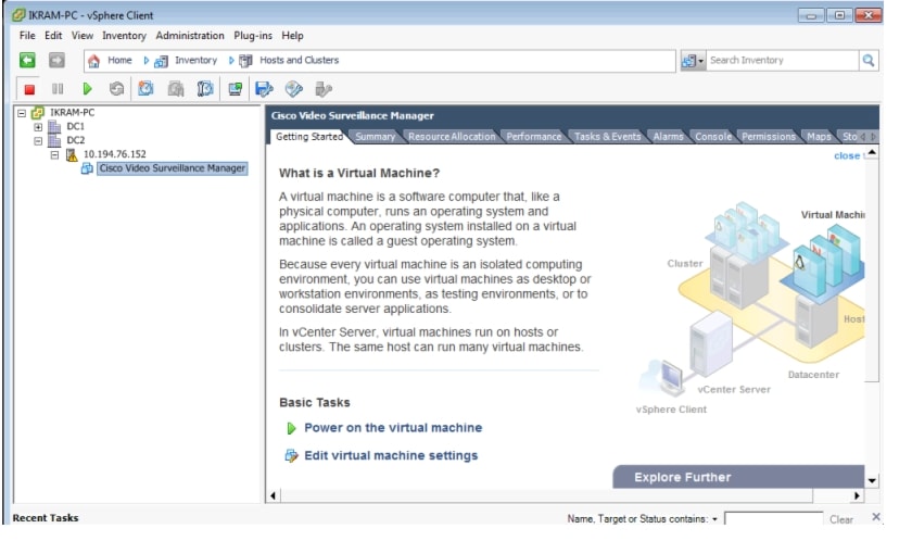
Once the VSM template is successfully deployed, the VSM VM displays under the hypervisor entry in the left-hand Inventory tree (Figure 14, left pane).
For more information about OVF Templates, see http://www.vmware.com/technical-resources/interfaces/ovf.html.
Note
Figure 14 VSM VM Console in the vSphere Client
Creating New Media Hard Disks
The size of a new media hard disk is based on the redundant array of independent disks (RAID) configuration of the hypervisor. If the hypervisor is configured with a RAID 0 setting, then the usable disk size for the media partition is 860 GB; if using a RAID 1 setting, then the usable disk size is 400 GB. A RAID configuration is specified when the SRE module is ordered.
Note
To create a new media hard disk for the VSM VM:
Step 1
Step 2
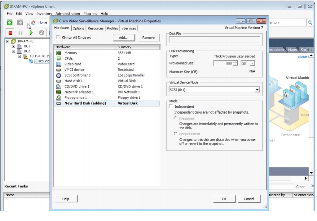
Figure 15 vCenter UCS, vSphere Client—Edit Settings
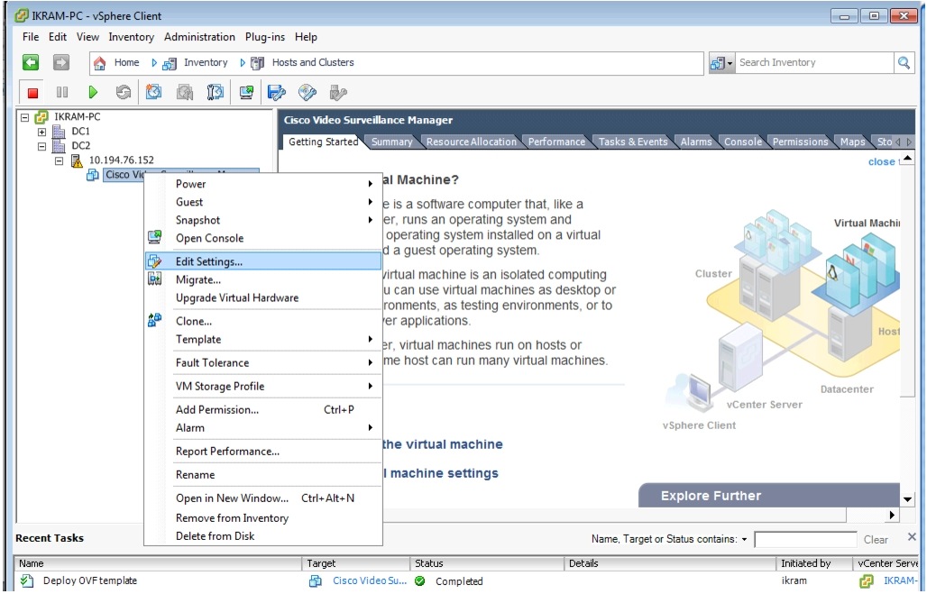
Figure 16 Virtual Machine Properties—Hardware Tab Settings
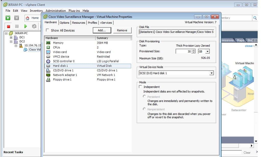
Step 3
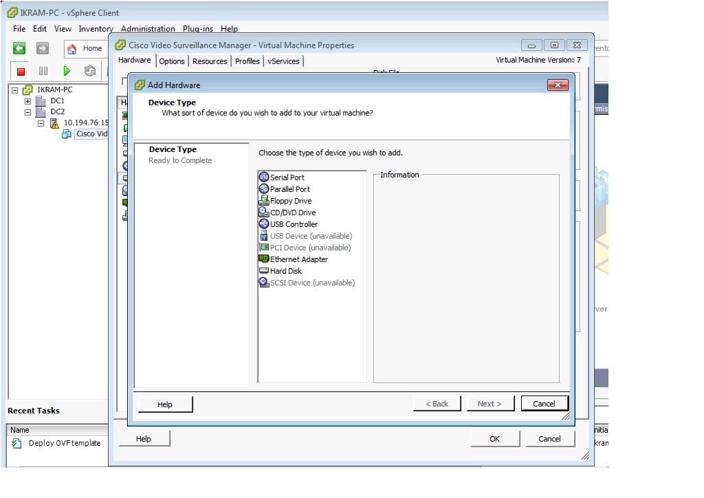
Step 4
Figure 17 Selecting a Hard Disk
Step 5
Step 6
Figure 18 Summary of New Hard Disk Options
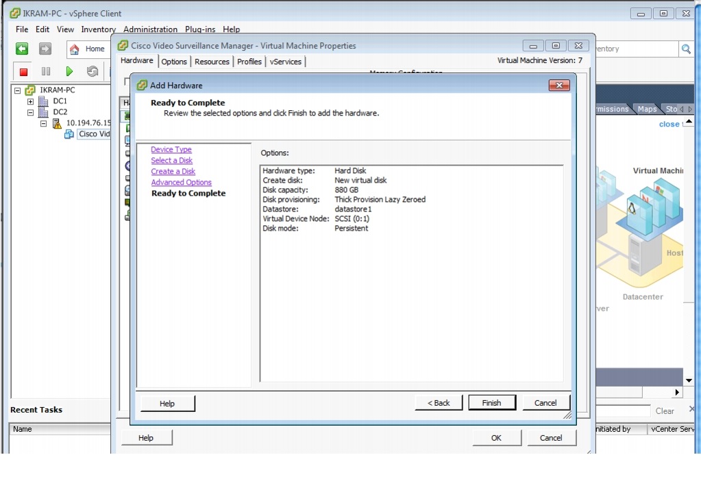
Step 7
Step 8
Figure 19 Ready to Add New Hard Disk to VSM VM
Configuring Network Switches for the VSM VM
To set up the networking configuration for the VSM VM:
Step 1
Step 2
Step 3
Figure 20 VM Switch Networking Properties—vSphere Client
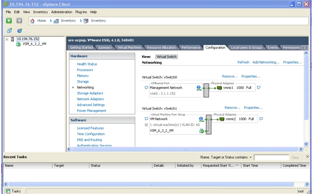
The defaults, Virtual Switch: vSwitch 0 and Virtual Switch: vSwitch1, display.
Step 4
Figure 21 VM Switch1 Networking Properties—vSphere Client
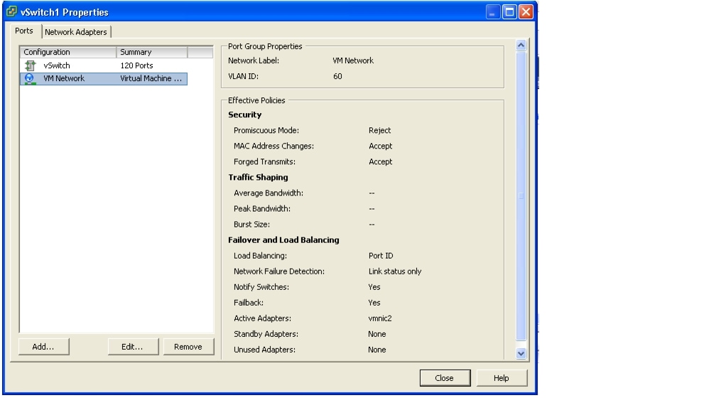
Step 5
Step 6
Figure 22 VM Networking Properties—vSphere Client
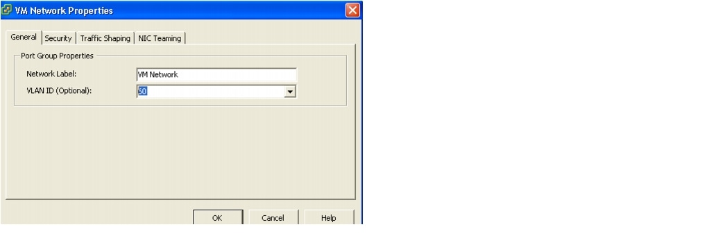
Step 7
Configuring NTP
Note
To set up the NTP configuration for the VSM VM:
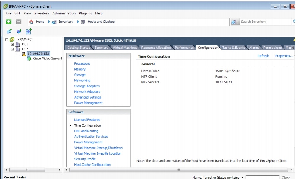
Step 1
Step 2
Step 3
Figure 23 Time Configuration Properties—NTP Settings
Step 4
Step 5
Figure 24 Time Configuration—General Properties
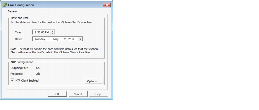
Figure 25 NTP Daemon Options
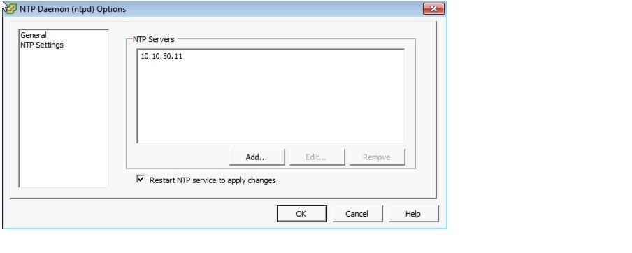
Step 6
Note
Launching the VSM VM
To launch the VSM VM:
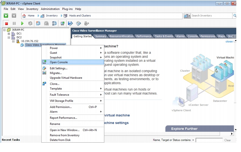
Step 1
Figure 26 Opening the VSM VM Console
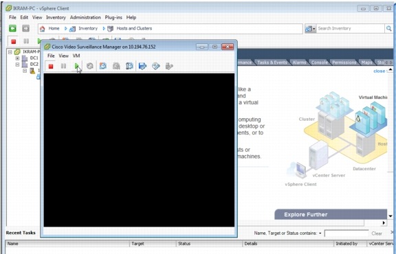
Step 2
Figure 27 Launching the VSM VM Console
Configuring the VSM VM
To configure the VSM VM:
Step 1
Step 2
Figure 28 Creating a New Media Partition in YaST
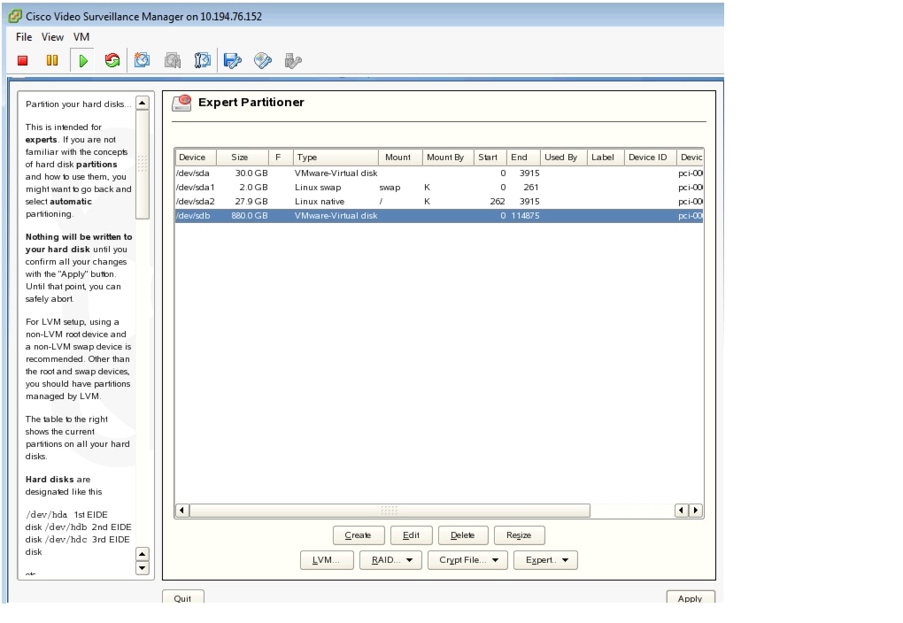
Figure 29 Selecting the Disk Device to Partition in YaST
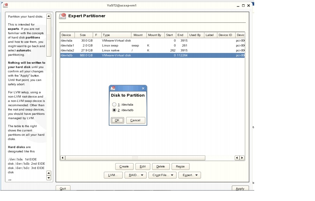
Figure 30 Selecting Partition Type in YaST
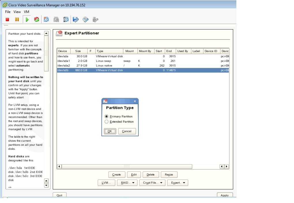
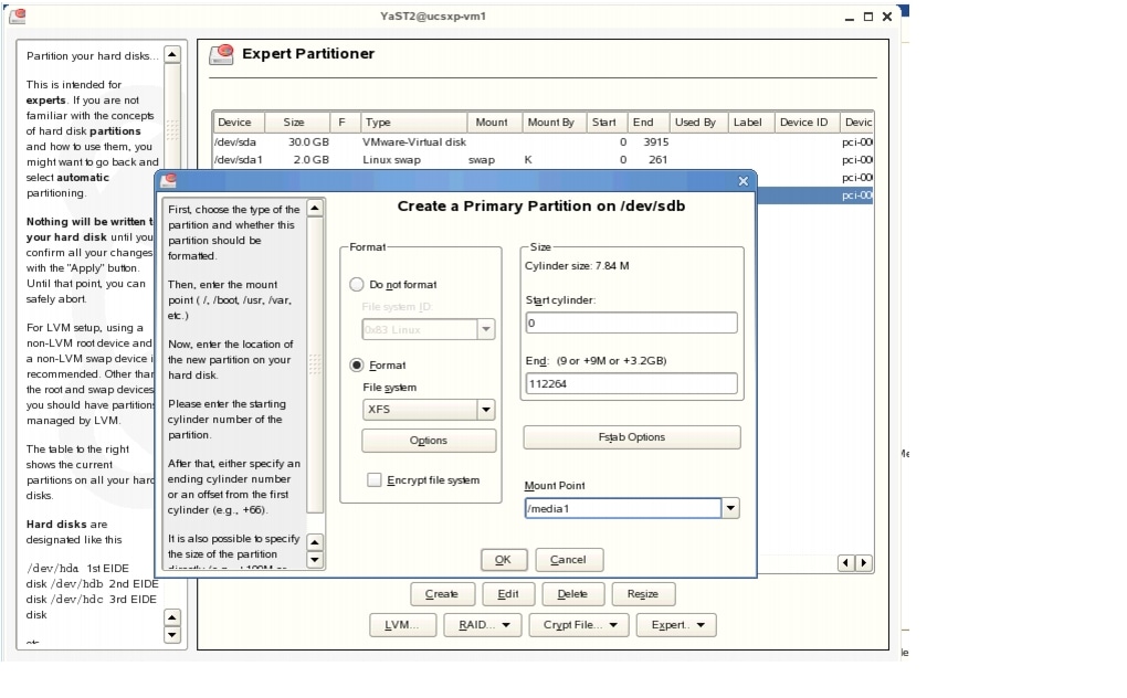
Figure 31 Using XFS Format—Choose Partition Size and Name the Mount Point in YaST
Step 3
Step 4
Step 5
Note
Testing Network Connectivity
To verify that network connectivity is working properly between endpoints, including IP cameras and VSOM operator workstations:
Step 1
Step 2
More Information
For more information about Cisco-related products, see the following resources:
•
http://www.cisco.com/go/physec/•
http://www.cisco.com/en/US/products/ps11273/prod_installation_guides_list.html•
•
•
http://www.cisco.com/en/US/docs/net_mgmt/configuration_engine/3.0/administration/guide/upgrade.html•
http://www.cisco.com/en/US/docs/interfaces_modules/services_modules/sre_v/2.0/user/guide/overview.html
 Feedback
Contact Cisco
- Open a Support Case

- (Requires a Cisco Service Contract)