Cisco Video Surveillance Deployment Guide for B- and C-Series Platforms
Available Languages
Table Of Contents
Video Surveillance Deployment Guide for UCS B- and C-Series Platforms
Installing and Configuring the VSM Software, Release 6.3.2
Fiber Channel-based SAN Storage
Internal Storage on C-Series Disks
Configuring Network Switches for the VSM VM
Video Surveillance Deployment Guide for UCS B- and C-Series Platforms
November 2012This guide describes the key requirements and instructions for deploying a virtualized Cisco® Video Surveillance Manager (VSM) on the Cisco Unified Computing System™ (UCS) B- and C-Series platforms.
Contents
This document includes the following sections:
Installing and Configuring the VSM Software, Release 6.3.2
Configuring Network Switches for the VSM VM
Introduction
This guide describes the key requirements and instructions for deploying a virtualized VSM on the Cisco UCS B- and C-Series platforms. This guide also describes installation and configuration guidelines for VMware vSphere Hypervisor and the VSM virtual machine (VM), as well as best practice recommendations.
Audience
This guide is intended for use by Cisco System Engineers, Physical Security Advanced Technology Provider (ATP) partners, and technical field staff who develop and implement Cisco Video Surveillance and UCS Servers for data center and branch office solutions.
A successful implementation also requires additional knowledge in the following areas:
•
Cisco UCS B- and C-Series installation and management
•
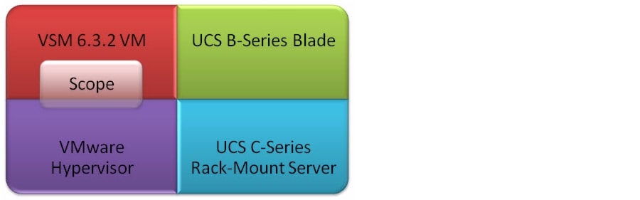
Scope
This guide contains detailed instructions on how to install the VSM on the UCS (see deployment scope in Figure 1).
Figure 1 Deployment Scope

Note
System Overview
The Cisco UCS fuses access layer networking and servers. This high-performance, next-generation server system provides a data center with a high degree of workload agility and scalability.
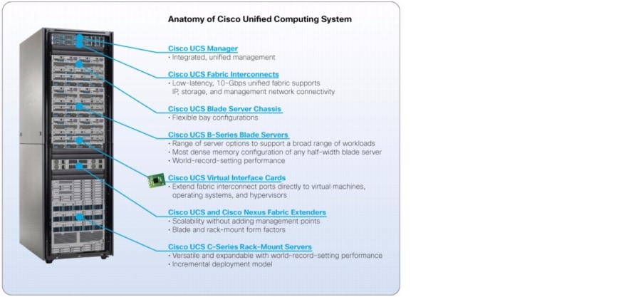
The Cisco Unified Computing System Manager (UCSM) presents a new paradigm for server management (see Figure 2). Among the most relevant attributes of UCSM include the following:
•
•
•
•
Figure 2 Anatomy of the Cisco UCS
The hardware (see Figure 3) and software components support the Cisco unified fabric, which runs multiple types of data center traffic over a single, converged network adapter.
Figure 3 UCS B-Series Chassis, B-Series Blades, C-Series Rack-Mount Servers, and Fabric Interconnects
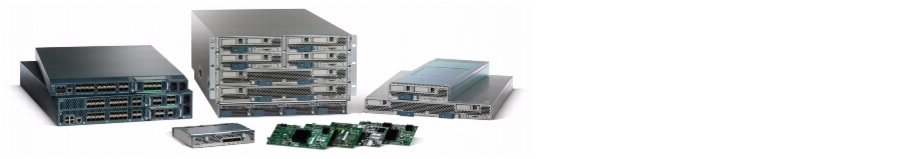
Figure 4 illustrates the overall, logical topology of the networking and video surveillance components, including a UCS B-Series Chassis containing the B-Series Server Blades that run the VSM and the Video Surveillance Operations Manager (VSOM), various IP cameras, an external switch, and the operator workstations that run the VSOM client.
Figure 4 Logical Network Topology

Note
Installing and Configuring the VSM Software, Release 6.3.2
This section describes the installation procedure, including the configuration of Hypervisor services and guest clients, and deploying and verifying the VSM VM.
Assumptions
In the following configuration examples, it is assumed that:
•
•
•
•
Pre-Installation Requirements
Table 1 outlines the pre-installation requirements for the vSphere Client.
To install the VSM software, Release 6.3.2:
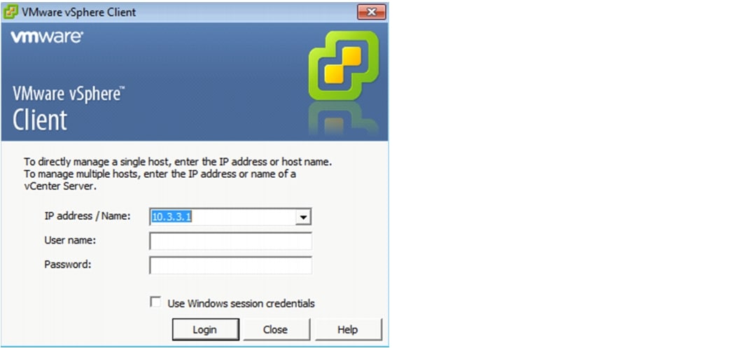
Step 1
Figure 5 VMware vSphere Client Login Page
Step 2
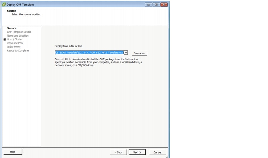
The OVF Template is approximately 2.5 GB in size. Once deployed, the VM requires 20 GB of space (without including the space for the video partitions).
The vSphere Client main page displays (see Figure 6).
Figure 6 Deploying the OVF Template

Step 3
Figure 7 Deploying the OVF Template from a File or URL
Step 4
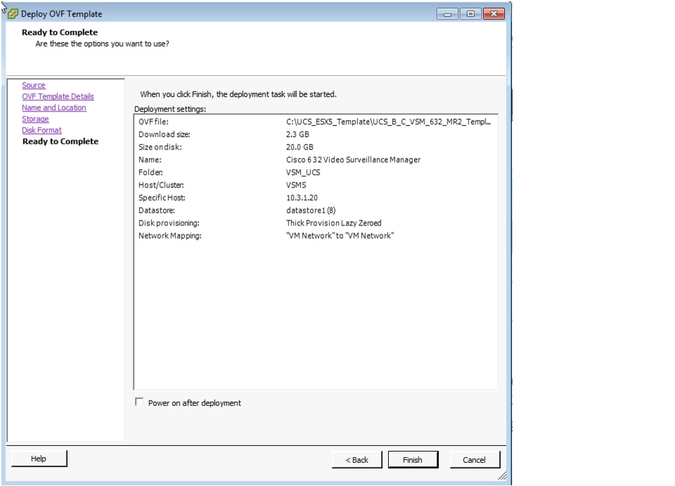
Step 5
Figure 8 displays the result of those selected deployment settings.
Figure 8 Ready to Complete—Deployment Settings
Step 6
For more information about OVF Templates, see http://www.vmware.com/technical-resources/interfaces/ovf.html.
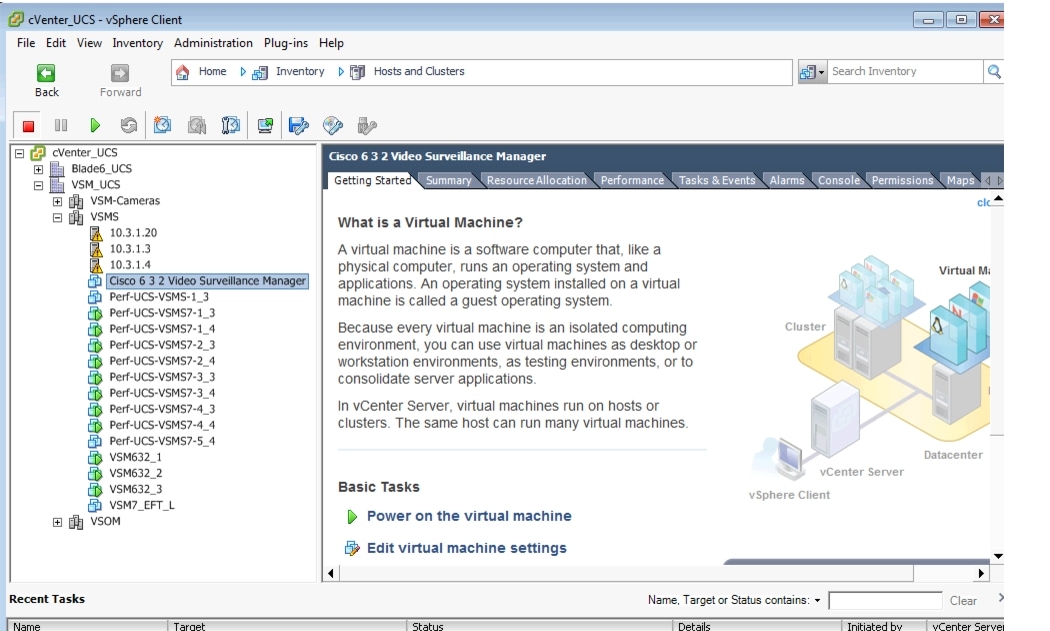
Once the VSM template is successfully deployed, the VSM VM displays under the host entry in the Inventory tree (see Figure 9, left pane).
Note
Figure 9 VSM VM Console in the vSphere Client
Creating New Media Hard Disks
The hard disk size depends on the SAN logical unit number (LUN) size for the B-Series or the RAID array for the C-Series UCS servers.
Fiber Channel-based SAN Storage
Fiber Channel-based SAN storage (B-Series blades and C-Series rack-mount servers) includes the following guidelines:
•
•
Internal Storage on C-Series Disks
Internal storage on C-Series disks include the following guidelines:
•
•
For more information about Virtual Machine File Systems (VMFS) and RDMs, see http://pubs.vmware.com/vi301/san_cfg/wwhelp/wwhimpl/common/html/wwhelp.htm?context=san_cfg&file=esx_san_cfg_esx_and_san.4.13.html.
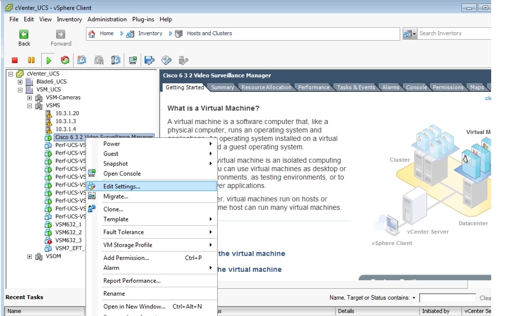
To add a second hard disk for the VSM VM:
Step 1
Figure 10 vCenter UCS, vSphere Client—Edit Settings
Step 2
Figure 11 Virtual Machine Properties—Hardware Tab Settings
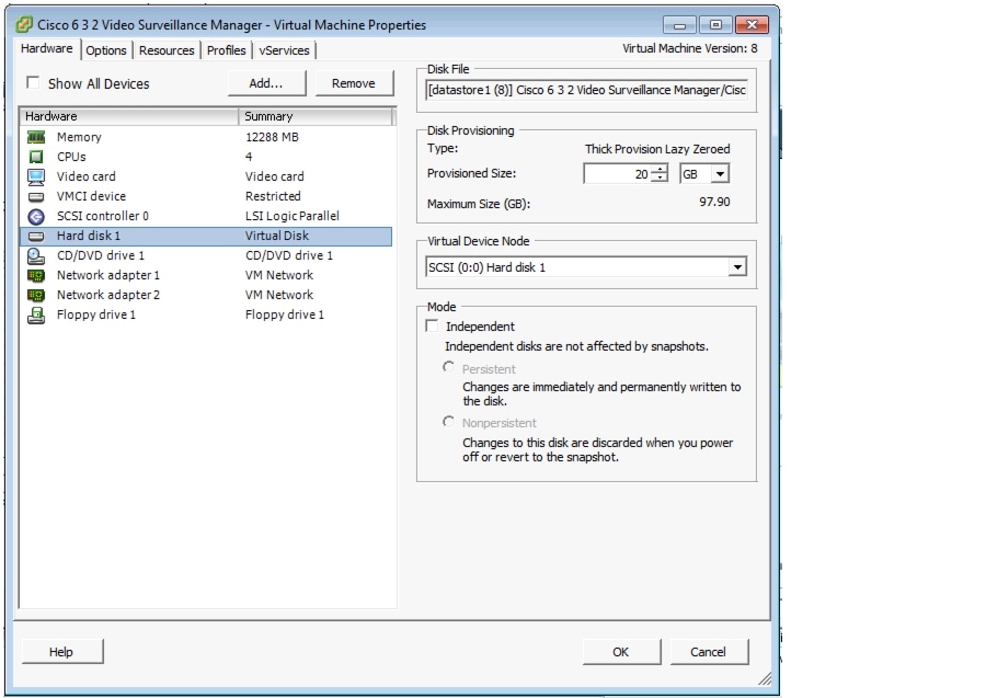
Step 3
Step 4
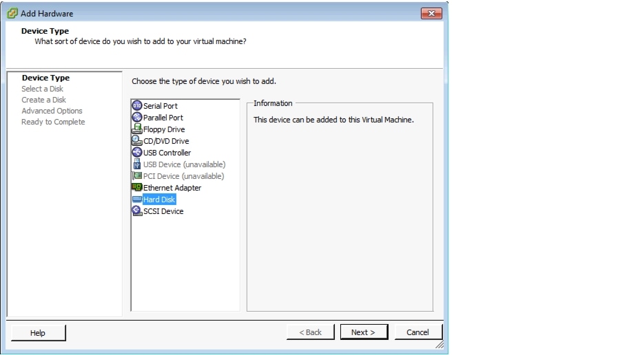
Figure 12 Selecting a Hard Disk
Step 5
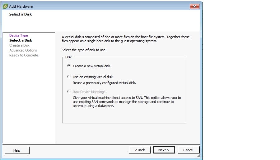
Figure 13 Disk Options available for UCS C-Series Internal RAID-based Storage
Step 6
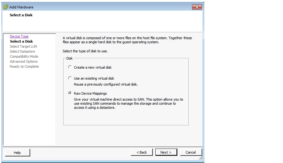
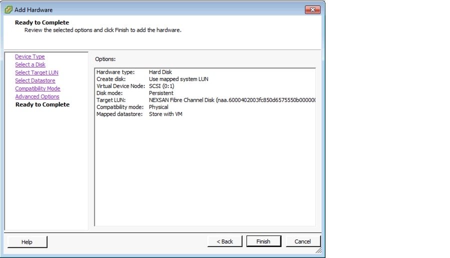
Figure 14 Disk Options Available for UCS B-Series Fiber Channel-based SAN Storage
Step 7
Figure 15 New Hard Disk Summary Options
Step 8
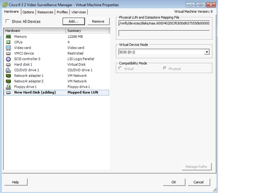
Figure 16 VM Properties—Add New Hard Disk to the VSM VM
Step 9
Configuring Network Switches for the VSM VM
To set up and change the networking configuration for the VSM VM to operate in the customer environment:
Step 1
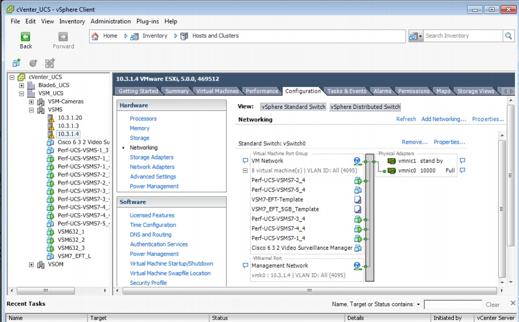
Figure 17 VM Switch Networking Properties—vSphere Client
Step 2
The default Virtual Switch: vSwitch 0 displays.
Step 3
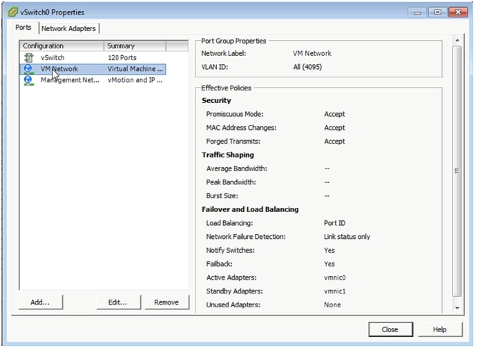
Figure 18 VM Switch Networking Properties—vSphere Client
Step 4
The VM Network Properties screen displays (see Figure 19).
Figure 19 VM Network Properties—vSphere Client
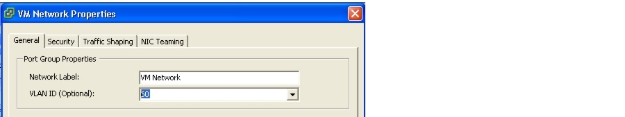
Step 5
Note
Step 6
For more information about configuring network switches for VLAN tagging in VMware, see http://kb.vmware.com/selfservice/microsites/search.do?language=en_US&cmd=displayKC&externalId=1266.
For information about VLAN tagging, see http://pubs.vmware.com/vsphere-50/index.jsp?topic=%2Fcom.vmware.vsphere.networking.doc_50%2FGUID-7225A28C-DAAB-4E90-AE8C-795A755FBE27.html.
For information about VMware vSphere documentation, see http://www.vmware.com/support/pubs/vsphere-esxi-vcenter-server-pubs.html.
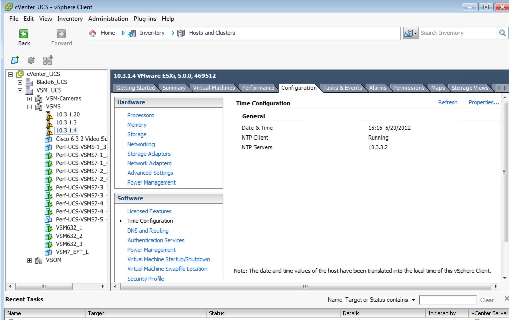
Configuring NTP
Note
To set up the NTP configuration for the VM host:
Step 1
Step 2
Figure 20 Time Configuration Settings
Step 3
Figure 21 Time Configuration Properties
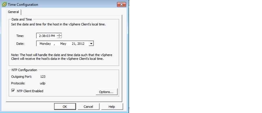
Step 4
Figure 22 Adding the NTP Server Address
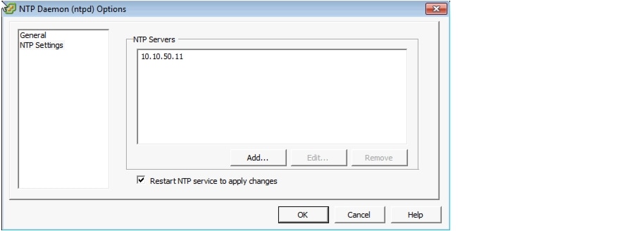
Step 5
Note
Powering On the VSM
To power on the VSM:
Step 1
Step 2
Figure 23 Opening the VM Console
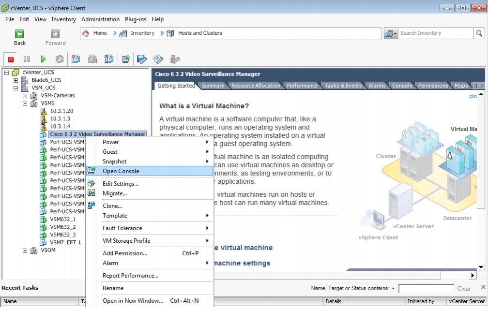
Figure 24 Launching the VM Console—Cisco 6.3.2 Video Surveillance Manager
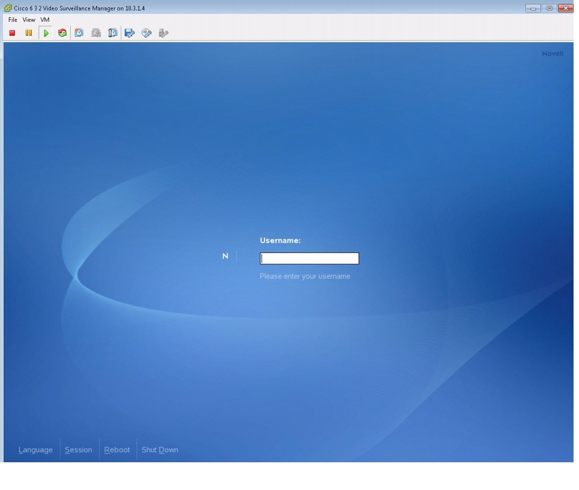
Step 3
Configuring the VSM
This section describes how to add a media partition to the VSM VM.
For other relevant, configuration steps for VSM 6.3.2, see http://www.cisco.com/en/US/products/ps9152/prod_installation_guides_list.html.
Preparing Video Repositories
Video that is recorded by the VSMS is stored in repositories on storage volumes that are dedicated for recording video by the VSMS. The repositories must be separate partitions from the operating system (OS) partitions.
Each repository has a mount point to specify the path through which the files are accessed. The common convention for naming repositories is
/media#, with/media0used for a repository on the operating system volume, and/media1 - /mediaNused for additional storage volumes.Repository Greater Than 2 TiB
To create partitions greater than 2 TiB, the volume must use a globally unique identifier (GUID) partition table (GPT) and must be a different storage volume from the OS volume.
Note

Caution
Step 1
linux:~ # parted /dev/<device> mklabel gpta.
b.
c.
linux:~ # parted /dev/sdb printDisk geometry for /dev/sdb: 0kB - 10TBDisk label type: gptNumber Start End Size File system Name FlagsInformation: Do not forget to update /etc/fstab, if necessary.d.
Step 2
a.
b.
Figure 25 Creating a New Media Partition in YaST
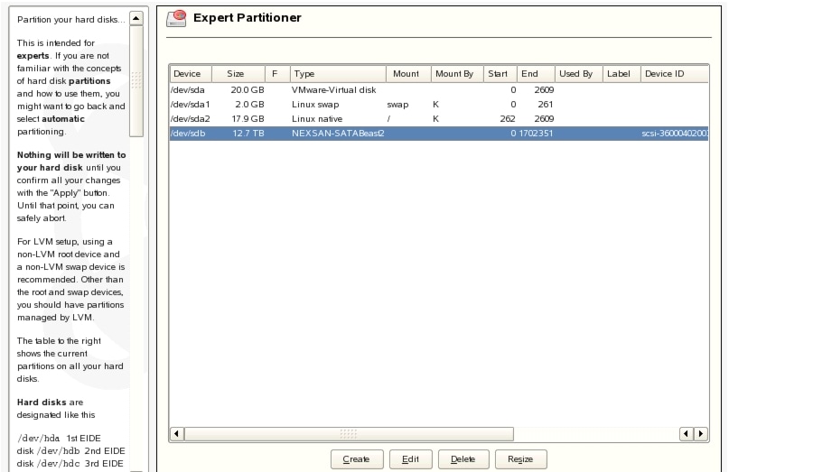
c.
Figure 26 Selecting the Disk Device to Partition in YaST
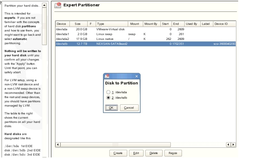
d.
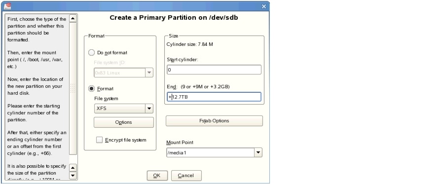
Figure 27 Create a Primary Partition on /dev/sdb
e.
f.
Step 3
Step 4
Table 2 lists the available storage options.
Table 2 Storage Options
•
•
•
•
Note
Testing Network Connectivity
To verify that network connectivity is working properly between endpoints, including IP cameras and VSOM operator workstations:
Step 1
Step 2
Step 3
More Information
For more information about Cisco-related products, see the following resources:
Cisco Physical Security and Building Systems:
http://www.cisco.com/go/physec/Cisco Video Surveillance Media Server Software—Install and Upgrade Guides:
http://www.cisco.com/en/US/products/ps9152/prod_installation_guides_list.htmlCisco Unified Computing and Servers:
http://www.cisco.com/en/US/products/ps10265/index.htmlInstalling and Configuring VMware Tools:
http://www.vmware.com/pdf/vmware-tools-installation-configuration.pdfVMware ESXi Configuration Guides:
http://www.vmware.com/support/pubs/vsphere-esxi-vcenter-server-pubs.htmlCisco UCS Site Preparation Guide
http://www.cisco.com/en/US/docs/unified_computing/ucs/hw/site_prep/guide/ucs_site_prep.htmlCisco UCS Manager GUI Configuration Guide
•
•
Cisco UCS 6100 Series Fabric Interconnect Hardware Installation Guide
http://www.cisco.com/en/US/docs/unified_computing/ucs/hw/switch/install/ucs6100_install.htmlCisco UCS 5108 Server Chassis Installation Guide
http://www.cisco.com/en/US/docs/unified_computing/ucs/hw/chassis/install/ucs5108_install.htmlCisco UCS C-Series Rack Servers Installation and Upgrade Guides
http://www.cisco.com/en/US/products/ps10493/prod_installation_guides_list.htmlCisco UCS Servers RAID Guide
http://www.cisco.com/en/US/docs/unified_computing/ucs/c/sw/raid/configuration/guide/RAID_GUIDE.htmlCisco UCS B-Series Blade Servers VMware Installation Guide
http://www.cisco.com/en/US/docs/unified_computing/ucs/sw/b/os/vmware/install/bseries-vmware-install.htmlCisco UCS Manager Configuration Guides
http://www.cisco.com/en/US/products/ps10281/products_installation_and_configuration_guides_list.htmlFor more information about configuring network switches for VLAN tagging in VMware, see http://kb.vmware.com/selfservice/microsites/search.do?language=en_US&cmd=displayKC&externalId=1266.
For information about VLAN tagging, see http://pubs.vmware.com/vsphere-50/index.jsp?topic=%2Fcom.vmware.vsphere.networking.doc_50%2FGUID-7225A28C-DAAB-4E90-AE8C-795A755FBE27.html.
For more information about VMWare vSphere documentation, see http://www.vmware.com/support/pubs/vsphere-esxi-vcenter-server-pubs.html.
 Feedback
Contact Cisco
- Open a Support Case

- (Requires a Cisco Service Contract)