Installing and Removing Interface Cards in Cisco IPS-4260 and IPS 4270-20
Available Languages
Table Of Contents
Removing and Installing Interface Cards in Cisco IPS-4260 and IPS 4270-20
Hardware and Software Requirements
Hardware Bypass Configuration Restrictions
Installing Interface Cards in IPS-4260
Removing and Replacing the Chassis Cover
Installing and Removing Interface Cards
Installing Interface Cards in IPS 4270-20
Removing and Replacing the Chassis Cover
Installing and Removing Interface Cards
Obtaining Documentation and Submitting a Service Request
Removing and Installing Interface Cards in Cisco IPS-4260 and IPS 4270-20
This document describes the IPS interface cards and how to install them in IPS-4260 and IPS 4270-20. It contains the following sections:
•
Working in an ESD Environment
•
•
•
•
Electrical Safety Guidelines

Warning
Follow these guidelines when working on equipment powered by electricity:
•
•
•
•
•
–
–
–
–
•
•
•
•
Other DC power guidelines are listed in Regulatory Compliance and Safety Information for the Cisco Intrusion Prevention System 4200 Series Appliance Sensor.
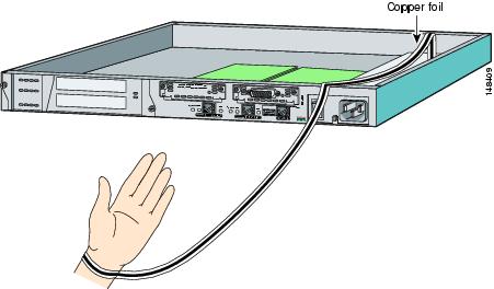
Working in an ESD Environment
Work on ESD-sensitive parts only at an approved static-safe station on a grounded static dissipative work surface, for example, an ESD workbench or static dissipative mat.
To remove and replace components in a sensor, follow these steps:
Step 1
Step 2

Note
Step 3
Step 4

Caution
Note
Supported Interface Cards
IPS-4260 and IPS 4270-20 support three interface cards: the 4GE bypass interface card, the 2SX interface card, and the 10GE interface card.
4GE Bypass Interface Card
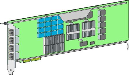
The 4GE bypass interface card (part numbers IPS-4GE-BP-INT and IPS-4GE-BP-INT=) provides four 10/100/1000BASE-T (4GE) monitoring interfaces. The IPS-4260 supports up to two 4GE bypass interfaces cards for a total of eight GE bypass interfaces. The IPS 4270-20 supports up to four 4GE bypass interface cards for a total of sixteen GE bypass interfaces.
The 4GE bypass interface card supports hardware bypass.
Figure 1 shows the 4GE bypass interface card.
Figure 1 4GE Bypass Interface Card
2SX Interface Card
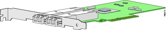
The 2SX interface card (part numbers IPS-2SX-INT and IPS-2SX-INT=) provides two 1000BASE-SX (fiber) monitoring interfaces. The IPS-4260 supports up to two 2SX interface cards for a total of four SX interfaces. The IPS 4270-20 supports up to six 2SX interface cards for a total of twelve SX interfaces.
The 2SX card ports require a multi-mode fiber cable with an LC connector to connect to the SX interface of the sensor.
The 2SX interface card does not support hardware bypass.
Figure 2 shows the 2SX interface card.
Figure 2 2SX Interface Card
10GE Interface Card
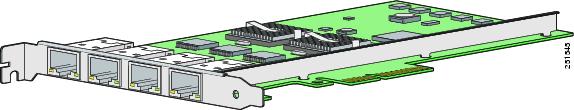
The 10GE interface card (part numbers IPS-2X10GE-SR-INT and IPS-2X10GE-SR-INT=) provides two 10000 Base-SX (fiber) interfaces. The IPS-4260 supports one 10GE interface card for a total of two 10GE fiber interfaces. The IPS 4270-20 supports up to two 10GE interface cards for a total of four 10GE fiber interfaces.
The card ports require a multi-mode fiber cable with an LC connector to connect to the SX interface of IPS-4260 and IPS 4270-20.
The 10GE interface card does not support hardware bypass.
Figure 3 shows the 10GE interface card.
Figure 3 10GE Interface Card
Hardware and Software Requirements
The IPS interface cards have the following hardware and software requirements:
•
–
–
•
–
–
–
Hardware Bypass
This section describes the 4GE bypass interface card and its configuration restrictions. It contains the following topics:
•
4GE Bypass Interface Card
IPS-4260 and IPS 4270-20 support the 4-port GigabitEthernet card (part number IPS-4GE-BP-INT=) with hardware bypass. This 4GE bypass interface card supports hardware bypass only between ports 0 and 1 and between ports 2 and 3.
Note
Hardware bypass complements the existing software bypass feature in Cisco IPS. The following conditions apply to hardware bypass and software bypass:
•
For each inline interface for which hardware bypass is available, the component interfaces are set to disable the fail-open capability. If SensorApp fails, the sensor is powered off, reset, or if the NIC interface drivers fail or are unloaded, the paired interfaces enter the fail-closed state (no traffic flows through inline interface or inline VLAN subinterfaces).
•
Software bypass forwards packets between the paired physical interfaces in each inline interface and between the paired VLANs in each inline VLAN subinterface. For each inline interface on which hardware bypass is available, the component interfaces are set to standby mode. If the sensor is powered off, reset, or if the NIC interfaces fail or are unloaded, those paired interfaces enter fail-open state in hardware (traffic flows unimpeded through inline interface). Any other inline interfaces enter fail-closed state.
•
For each inline interface on which hardware bypass is available, the component interfaces are set to standby mode. If the sensor is powered off, reset, or if the NIC interfaces fail or are unloaded, those paired interfaces enter fail-open state in hardware. Any other inline interfaces enter the fail-closed state.
Note
Hardware Bypass Configuration Restrictions
To use the hardware bypass feature on the 4GE bypass interface card, you must pair interfaces to support the hardware design of the card. If you create an inline interface that pairs a hardware-bypass-capable interface with an interface that violates one or more of the hardware-bypass configuration restrictions, hardware bypass is deactivated on the inline interface and you receive a warning message similar to the following:
Hardware bypass functionality is not available on Inline-interface pair0.
Physical-interface GigabitEthernet2/0 is capable of performing hardware bypass only when
paired with GigabitEthernet2/1, and both interfaces are enabled and configured with the
same speed and duplex settings.
The following configuration restrictions apply to hardware bypass:
•
•
•
–
–
–
–
–
•
You must configure both the sensor ports and the switch ports for autonegotiation for hardware bypass to work. The switch ports must support MDI/X, which automatically reverses the transmit and receive lines if necessary to correct any cabling problems. The sensor is only guaranteed to operate correctly with the switch if both of them are configured for identical speed and duplex, which means that the sensor must be set for autonegotiation too.
Installing Interface Cards in IPS-4260
This section describes how to install interface cards in IPS-4260, and contains the following topics:
•
•
Removing and Replacing the Chassis Cover
Warning
Warning
Warning
Warning
Caution
Note
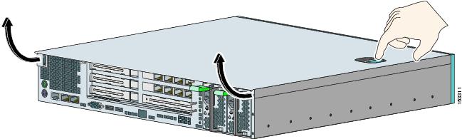
To remove and replace the chassis cover, follow these steps:
Step 1
Step 2
sensor# reset powerdownWait for the power down message before continuing with Step 3.
Note
Step 3
Step 4
Step 5
Step 6
Step 7
Caution
Step 8
Step 9
Step 10
Step 11
For More Information
For the procedure for removing IPS-4260 from a rack, refer to "Installing IPS-4260," in Installing Cisco Intrusion Prevention System Appliances and Modules.
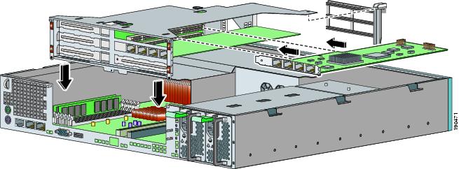
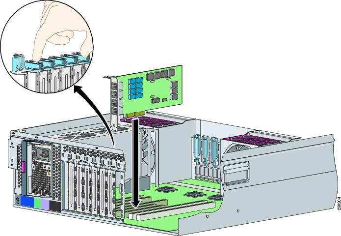
Installing and Removing Interface Cards
IPS-4260 has 6 expansion card slots, three full-height and three half-height slots. You can install the optional network interface cards in the two top full-height slots, slots 2 and 3. IPS-4260 supports up to two network interface cards.
Note
Note
To install and remove PCI cards, follow these steps:
Step 1
Step 2
sensor# reset powerdownWait for the power down message before continuing with Step 3.
Note
Step 3
Step 4
Step 5
Step 6
Step 7
Step 8

Step 9
Step 10
If the card is full length, use a screw driver to remove the blue thumb screw from the card support at the back of the card carrier.
Step 11
Step 12
Step 13
Step 14
Installing Interface Cards in IPS 4270-20
This section describes how to install interface cards in IPS 4270-20, and contains the following topics:
•
•
Removing and Replacing the Chassis Cover
Warning
Warning
Warning
Warning
Note
Caution
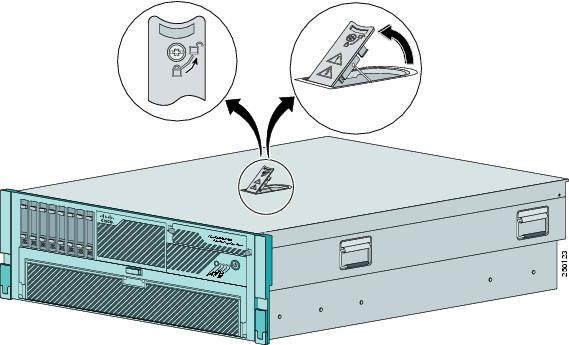
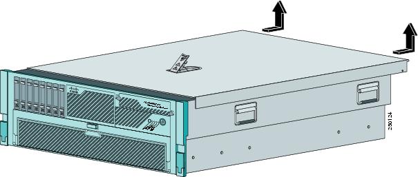
To remove and replace the chassis cover, follow these steps:
Step 1
Step 2
sensor# reset powerdownWait for the power down message before continuing with Step 3.
Note
Step 3
Step 4
Step 5
Step 6
Step 7
Step 8
Step 9
Caution
Step 10
Note
Step 11
Step 12
Step 13
For More Information
For the procedure for removing IPS 4270-20 from a rack, refer to "Installing IPS 4270-20," in Installing Cisco Intrusion Prevention System Appliances and Modules.
Installing and Removing Interface Cards
IPS 4270-20 has nine expansion card slots. Slots 1 and 2 are PCI-X slots and are reserved for future use. Slots 3 through 9 are PCI-Express slots. All slots are full-height slots. Slot 9 is populated by a RAID controller card and is not available for use by network interface cards.
Note
Caution
Caution
To install and remove PCI cards, follow these steps:
Step 1
Step 2
sensor# reset powerdownWait for the power down message before continuing with Step 3.
Note
Step 3
Step 4
Step 5
Step 6
Step 7
Step 8
Step 9
Note
Step 10
Step 11
Step 12
Step 13
Related Documentation
For more information on Cisco IPS, refer to the following documentation found at this URL:
http://www.cisco.com/en/US/products/hw/vpndevc/ps4077/tsd_products_support_series_home.html
•
•
•
•
•
•
•
•
Obtaining Documentation and Submitting a Service Request
For information on obtaining documentation, submitting a service request, and gathering additional information, see the monthly What's New in Cisco Product Documentation, which also lists all new and revised Cisco technical documentation, at:
http://www.cisco.com/en/US/docs/general/whatsnew/whatsnew.html
Subscribe to the What's New in Cisco Product Documentation as a Really Simple Syndication (RSS) feed and set content to be delivered directly to your desktop using a reader application. The RSS feeds are a free service and Cisco currently supports RSS Version 2.0.
This document is to be used in conjunction with the documents listed in the "Related Documentation" section.
CCDE, CCSI, CCENT, Cisco Eos, Cisco HealthPresence, the Cisco logo, Cisco Lumin, Cisco Nexus, Cisco Nurse Connect, Cisco Stackpower, Cisco StadiumVision, Cisco TelePresence, Cisco WebEx, DCE, and Welcome to the Human Network are trademarks; Changing the Way We Work, Live, Play, and Learn and Cisco Store are service marks; and Access Registrar, Aironet, AsyncOS, Bringing the Meeting To You, Catalyst, CCDA, CCDP, CCIE, CCIP, CCNA, CCNP, CCSP, CCVP, Cisco, the Cisco Certified Internetwork Expert logo, Cisco IOS, Cisco Press, Cisco Systems, Cisco Systems Capital, the Cisco Systems logo, Cisco Unity, Collaboration Without Limitation, EtherFast, EtherSwitch, Event Center, Fast Step, Follow Me Browsing, FormShare, GigaDrive, HomeLink, Internet Quotient, IOS, iPhone, iQuick Study, IronPort, the IronPort logo, LightStream, Linksys, MediaTone, MeetingPlace, MeetingPlace Chime Sound, MGX, Networkers, Networking Academy, Network Registrar, PCNow, PIX, PowerPanels, ProConnect, ScriptShare, SenderBase, SMARTnet, Spectrum Expert, StackWise, The Fastest Way to Increase Your Internet Quotient, TransPath, WebEx, and the WebEx logo are registered trademarks of Cisco Systems, Inc. and/or its affiliates in the United States and certain other countries.
All other trademarks mentioned in this document or website are the property of their respective owners. The use of the word partner does not imply a partnership relationship between Cisco and any other company. (0903R)
Any Internet Protocol (IP) addresses used in this document are not intended to be actual addresses. Any examples, command display output, and figures included in the document are shown for illustrative purposes only. Any use of actual IP addresses in illustrative content is unintentional and coincidental.
© 2009 Cisco Systems, Inc. All rights reserved.
Printed in the USA on recycled paper containing 10% postconsumer waste.

 Feedback
Contact Cisco
- Open a Support Case

- (Requires a Cisco Service Contract)