Implementing OSPF on Cisco IOS XR Software
Available Languages
Contents
- Implementing OSPF on Cisco IOS XR Software
- Prerequisites for Implementing OSPF
- Information About Implementing OSPF
- OSPF Functional Overview
- Key Features Supported in the Cisco IOS XR Software OSPF Implementation
- Comparison of Cisco IOS XR Software OSPFv3 and OSPFv2
- OSPF Hierarchical CLI and CLI Inheritance
- OSPF Routing Components
- Autonomous Systems
- Areas
- Backbone Area
- Stub Area
- Not-so-Stubby Area
- Routers
- Area Border Routers
- Autonomous System Boundary Routers (ASBR)
- Interior Routers
- OSPF Process and Router ID
- Supported OSPF Network Types
- Route Authentication Methods for OSPF
- Plain Text Authentication
- MD5 Authentication
- Authentication Strategies
- Key Rollover
- Neighbors and Adjacency for OSPF
- Designated Router (DR) for OSPF
- Default Route for OSPF
- Link-State Advertisement Types for OSPF Version 2
- Link-State Advertisement Types for OSPFv3
- Virtual Link and Transit Area for OSPF
- OSPFv2 Sham Link Support for MPLS VPN
- OSPFv2 SPF Prefix Prioritization
- Route Redistribution for OSPF
- OSPF Shortest Path First Throttling
- Nonstop Forwarding for OSPF Version 2
- Graceful Restart for OSPFv3
- Modes of Graceful Restart Operation
- Restart Mode
- Helper Mode
- Graceful Restart Requirements and Restrictions
- Warm Standby and Nonstop Routing for OSPF Version 2
- Warm Standby for OSPF Version 3
- Multicast-Intact Support for OSPF
- Load Balancing in OSPF Version 2 and OSPFv3
- Multi-Area Adjacency for OSPF Version 2
- Label Distribution Protocol IGP Auto-configuration for OSPF
- OSPF Authentication Message Digest Management
- GTSM TTL Security Mechanism for OSPF
- Path Computation Element for OSPFv2
- OSPF Queue Tuning Parameters
- OSPF IP Fast Reroute Loop Free Alternate
- How to Implement OSPF
- Enabling OSPF
- Configuring Stub and Not-So-Stubby Area Types
- Configuring Neighbors for Nonbroadcast Networks
- Configuring Authentication at Different Hierarchical Levels for OSPF Version 2
- Controlling the Frequency That the Same LSA Is Originated or Accepted for OSPF
- Creating a Virtual Link with MD5 Authentication to Area 0 for OSPF
- Examples
- Summarizing Subnetwork LSAs on an OSPF ABR
- Redistributing Routes from One IGP into OSPF
- Configuring OSPF Shortest Path First Throttling
- Examples
- Configuring Nonstop Forwarding Specific to Cisco for OSPF Version 2
- Configuring OSPF Version 2 for MPLS Traffic Engineering
- Examples
- Configuring OSPFv3 Graceful Restart
- Displaying Information About Graceful Restart
- Configuring an OSPFv2 Sham Link
- Enabling Nonstop Routing for OSPFv2
- Configuring OSPFv2 SPF Prefix Prioritization
- Enabling Multicast-intact for OSPFv2
- Associating Interfaces to a VRF
- Configuring OSPF as a Provider Edge to Customer Edge (PE-CE) Protocol
- Creating Multiple OSPF Instances (OSPF Process and a VRF)
- Configuring Multi-area Adjacency
- Configuring Label Distribution Protocol IGP Auto-configuration for OSPF
- Configuring LDP IGP Synchronization: OSPF
- Configuring Authentication Message Digest Management for OSPF
- Examples
- Configuring Generalized TTL Security Mechanism (GTSM) for OSPF
- Examples
- Verifying OSPF Configuration and Operation
- Configuring OSPF Queue Tuning Parameters
- Configuring IP Fast Reroute Loop-free Alternate
- Enabling IPFRR LFA
- Excluding an Interface From IP Fast Reroute Per-link Computation
- Configuration Examples for Implementing OSPF
- Cisco IOS XR Software for OSPF Version 2 Configuration: Example
- CLI Inheritance and Precedence for OSPF Version 2: Example
- MPLS TE for OSPF Version 2: Example
- ABR with Summarization for OSPFv3: Example
- ABR Stub Area for OSPFv3: Example
- ABR Totally Stub Area for OSPFv3: Example
- Configuring OSPFv2 SPF Prefix Prioritization: Example
- Route Redistribution for OSPFv3: Example
- Virtual Link Configured Through Area 1 for OSPFv3: Example
- Virtual Link Configured with MD5 Authentication for OSPF Version 2: Example
- VPN Backbone and Sham Link Configured for OSPF Version 2: Example
- OSPF Queue Tuning Parameters Configuration: Example
- Where to Go Next
- Additional References
Implementing OSPF on Cisco IOS XR Software
Open Shortest Path First (OSPF) is an Interior Gateway Protocol (IGP) developed by the OSPF working group of the Internet Engineering Task Force (IETF). Designed expressly for IP networks, OSPF supports IP subnetting and tagging of externally derived routing information. OSPF also allows packet authentication and uses IP multicast when sending and receiving packets.
OSPF Version 3 (OSPFv3) expands on OSPF Version 2, providing support for IPv6 routing prefixes.
This module describes the concepts and tasks you need to implement both versions of OSPF on your Cisco XR 12000 Series Router . The term “OSPF�? implies both versions of the routing protocol, unless otherwise noted.
Note
For more information about OSPF on Cisco IOS XR software and complete descriptions of the OSPF commands listed in this module, see the Related Documents section of this module. To locate documentation for other commands that might appear during execution of a configuration task, search online in the Cisco IOS XR Commands Master List for the Cisco XR 12000 Series Router
- Prerequisites for Implementing OSPF
- Information About Implementing OSPF
- How to Implement OSPF
- Configuring IP Fast Reroute Loop-free Alternate
- Configuration Examples for Implementing OSPF
- Where to Go Next
- Additional References
Prerequisites for Implementing OSPF
The following are prerequisites for implementing OSPF on Cisco IOS XR software:
You must be in a user group associated with a task group that includes the proper task IDs. The command reference guides include the task IDs required for each command. If you suspect user group assignment is preventing you from using a command, contact your AAA administrator for assistance.
Configuration tasks for OSPFv3 assume that you are familiar with IPv6 addressing and basic configuration. See the Implementing Network Stack IPv4 and IPv6 on Cisco IOS XR Software module of the Cisco IOS XR IP Addresses and Services Configuration Guide for the Cisco XR 12000 Series Router for information on IPv6 routing and addressing.
- Before you enable OSPFv3 on an interface, you must perform the following tasks:
Configuring authentication (IP Security) is an optional task. If you choose to configure authentication, you must first decide whether to configure plain text or Message Digest 5 (MD5) authentication, and whether the authentication applies to an entire area or specific interfaces.
Information About Implementing OSPF
To implement OSPF you need to understand the following concepts:
- OSPF Functional Overview
- Key Features Supported in the Cisco IOS XR Software OSPF Implementation
- Comparison of Cisco IOS XR Software OSPFv3 and OSPFv2
- OSPF Hierarchical CLI and CLI Inheritance
- OSPF Routing Components
- OSPF Process and Router ID
- Supported OSPF Network Types
- Route Authentication Methods for OSPF
- Neighbors and Adjacency for OSPF
- Designated Router (DR) for OSPF
- Default Route for OSPF
- Link-State Advertisement Types for OSPF Version 2
- Link-State Advertisement Types for OSPFv3
- Virtual Link and Transit Area for OSPF
- OSPFv2 Sham Link Support for MPLS VPN
- OSPFv2 SPF Prefix Prioritization
- Route Redistribution for OSPF
- OSPF Shortest Path First Throttling
- Nonstop Forwarding for OSPF Version 2
- Graceful Restart for OSPFv3
- Warm Standby and Nonstop Routing for OSPF Version 2
- Warm Standby for OSPF Version 3
- Multicast-Intact Support for OSPF
- Load Balancing in OSPF Version 2 and OSPFv3
- Multi-Area Adjacency for OSPF Version 2
- Label Distribution Protocol IGP Auto-configuration for OSPF
- OSPF Authentication Message Digest Management
- GTSM TTL Security Mechanism for OSPF
- Path Computation Element for OSPFv2
- OSPF Queue Tuning Parameters
- OSPF IP Fast Reroute Loop Free Alternate
OSPF Functional Overview
OSPF is a routing protocol for IP. It is a link-state protocol, as opposed to a distance-vector protocol. A link-state protocol makes its routing decisions based on the states of the links that connect source and destination machines. The state of the link is a description of that interface and its relationship to its neighboring networking devices. The interface information includes the IP address of the interface, network mask, type of network to which it is connected, routers connected to that network, and so on. This information is propagated in various types of link-state advertisements (LSAs).
A router stores the collection of received LSA data in a link-state database. This database includes LSA data for the links of the router. The contents of the database, when subjected to the Dijkstra algorithm, extract data to create an OSPF routing table. The difference between the database and the routing table is that the database contains a complete collection of raw data; the routing table contains a list of shortest paths to known destinations through specific router interface ports.
OSPF is the IGP of choice because it scales to large networks. It uses areas to partition the network into more manageable sizes and to introduce hierarchy in the network. A router is attached to one or more areas in a network. All of the networking devices in an area maintain the same complete database information about the link states in their area only. They do not know about all link states in the network. The agreement of the database information among the routers in the area is called convergence.
At the intradomain level, OSPF can import routes learned using Intermediate System-to-Intermediate System (IS-IS). OSPF routes can also be exported into IS-IS. At the interdomain level, OSPF can import routes learned using Border Gateway Protocol (BGP). OSPF routes can be exported into BGP.
Unlike Routing Information Protocol (RIP), OSPF does not provide periodic routing updates. On becoming neighbors, OSPF routers establish an adjacency by exchanging and synchronizing their databases. After that, only changed routing information is propagated. Every router in an area advertises the costs and states of its links, sending this information in an LSA. This state information is sent to all OSPF neighbors one hop away. All the OSPF neighbors, in turn, send the state information unchanged. This flooding process continues until all devices in the area have the same link-state database.
To determine the best route to a destination, the software sums all of the costs of the links in a route to a destination. After each router has received routing information from the other networking devices, it runs the shortest path first (SPF) algorithm to calculate the best path to each destination network in the database.
The networking devices running OSPF detect topological changes in the network, flood link-state updates to neighbors, and quickly converge on a new view of the topology. Each OSPF router in the network soon has the same topological view again. OSPF allows multiple equal-cost paths to the same destination. Since all link-state information is flooded and used in the SPF calculation, multiple equal cost paths can be computed and used for routing.
On broadcast and nonbroadcast multiaccess (NBMA) networks, the designated router (DR) or backup DR performs the LSA flooding. On point-to-point networks, flooding simply exits an interface directly to a neighbor.
OSPF runs directly on top of IP; it does not use TCP or User Datagram Protocol (UDP). OSPF performs its own error correction by means of checksums in its packet header and LSAs.
In OSPFv3, the fundamental concepts are the same as OSPF Version 2, except that support is added for the increased address size of IPv6. New LSA types are created to carry IPv6 addresses and prefixes, and the protocol runs on an individual link basis rather than on an individual IP-subnet basis.
OSPF typically requires coordination among many internal routers: Area Border Routers (ABRs), which are routers attached to multiple areas, and Autonomous System Border Routers (ASBRs) that export reroutes from other sources (for example, IS-IS, BGP, or static routes) into the OSPF topology. At a minimum, OSPF-based routers or access servers can be configured with all default parameter values, no authentication, and interfaces assigned to areas. If you intend to customize your environment, you must ensure coordinated configurations of all routers.
Key Features Supported in the Cisco IOS XR Software OSPF Implementation
The Cisco IOS XR Software implementation of OSPF conforms to the OSPF Version 2 and OSPF Version 3 specifications detailed in the Internet RFC 2328 and RFC 2740, respectively.
The following key features are supported in the Cisco IOS XR Software implementation:
Hierarchy—CLI hierarchy is supported.
Inheritance—CLI inheritance is supported.
Stub areas—Definition of stub areas is supported.
NSF—Nonstop forwarding is supported.
SPF throttling—Shortest path first throttling feature is supported.
LSA throttling—LSA throttling feature is supported.
Fast convergence—SPF and LSA throttle timers are set, configuring fast convergence. The OSPF LSA throttling feature provides a dynamic mechanism to slow down LSA updates in OSPF during network instability. LSA throttling also allows faster OSPF convergence by providing LSA rate limiting in milliseconds.
Route redistribution—Routes learned using any IP routing protocol can be redistributed into any other IP routing protocol.
Authentication—Plain text and MD5 authentication among neighboring routers within an area is supported.
Routing interface parameters—Configurable parameters supported include interface output cost, retransmission interval, interface transmit delay, router priority, router “dead” and hello intervals, and authentication key.
Virtual links—Virtual links are supported.
Not-so-stubby area (NSSA)—RFC 1587 is supported.
OSPF over demand circuit—RFC 1793 is supported.
Comparison of Cisco IOS XR Software OSPFv3 and OSPFv2
Much of the OSPFv3 protocol is the same as in OSPFv2. OSPFv3 is described in RFC 2740.
The key differences between the Cisco IOS XR Software OSPFv3 and OSPFv2 protocols are as follows:
OSPFv3 expands on OSPFv2 to provide support for IPv6 routing prefixes and the larger size of IPv6 addresses.
When using an NBMA interface in OSPFv3, users must manually configure the router with the list of neighbors. Neighboring routers are identified by the link local address of the attached interface of the neighbor.
Unlike in OSPFv2, multiple OSPFv3 processes can be run on a link.
LSAs in OSPFv3 are expressed as “prefix and prefix length” instead of “address and mask.”
The router ID is a 32-bit number with no relationship to an IPv6 address.
OSPF Hierarchical CLI and CLI Inheritance
Cisco IOS XR Software introduces new OSPF configuration fundamentals consisting of hierarchical CLI and CLI inheritance.
Hierarchical CLI is the grouping of related network component information at defined hierarchical levels such as at the router, area, and interface levels. Hierarchical CLI allows for easier configuration, maintenance, and troubleshooting of OSPF configurations. When configuration commands are displayed together in their hierarchical context, visual inspections are simplified. Hierarchical CLI is intrinsic for CLI inheritance to be supported.
With CLI inheritance support, you need not explicitly configure a parameter for an area or interface. In Cisco IOS XR Software, the parameters of interfaces in the same area can be exclusively configured with a single command, or parameter values can be inherited from a higher hierarchical level—such as from the area configuration level or the router ospf configuration levels.
For example, the hello interval value for an interface is determined by this precedence “IF” statement:
If the hello interval command is configured at the interface configuration level, then use the interface configured value, else
If the hello interval command is configured at the area configuration level, then use the area configured value, else
If the hello interval command is configured at the router ospf configuration level, then use the router ospf configured value, else
Use the default value of the command.
Tip
Understanding hierarchical CLI and CLI inheritance saves you considerable configuration time. See Configuring Authentication at Different Hierarchical Levels for OSPF Version 2 to understand how to implement these fundamentals. In addition, Cisco IOS XR Software examples are provided in Configuration Examples for Implementing OSPF.
OSPF Routing Components
Before implementing OSPF, you must know what the routing components are and what purpose they serve. They consist of the autonomous system, area types, interior routers, ABRs, and ASBRs.
Autonomous Systems
The autonomous system is a collection of networks, under the same administrative control, that share routing information with each other. An autonomous system is also referred to as a routing domain. Figure 1 shows two autonomous systems: 109 and 65200. An autonomous system can consist of one or more OSPF areas.
Areas
Areas allow the subdivision of an autonomous system into smaller, more manageable networks or sets of adjacent networks. As shown in Figure 1, autonomous system 109 consists of three areas: Area 0, Area 1, and Area 2.
OSPF hides the topology of an area from the rest of the autonomous system. The network topology for an area is visible only to routers inside that area. When OSPF routing is within an area, it is called intra-area routing. This routing limits the amount of link-state information flood into the network, reducing routing traffic. It also reduces the size of the topology information in each router, conserving processing and memory requirements in each router.
Also, the routers within an area cannot see the detailed network topology outside the area. Because of this restricted view of topological information, you can control traffic flow between areas and reduce routing traffic when the entire autonomous system is a single routing domain.
Backbone Area
A backbone area is responsible for distributing routing information between multiple areas of an autonomous system. OSPF routing occurring outside of an area is called interarea routing.
The backbone itself has all properties of an area. It consists of ABRs, routers, and networks only on the backbone. As shown in Figure 1, Area 0 is an OSPF backbone area. Any OSPF backbone area has a reserved area ID of 0.0.0.0.
Stub Area
A stub area is an area that does not accept route advertisements or detailed network information external to the area. A stub area typically has only one router that interfaces the area to the rest of the autonomous system. The stub ABR advertises a single default route to external destinations into the stub area. Routers within a stub area use this route for destinations outside the area and the autonomous system. This relationship conserves LSA database space that would otherwise be used to store external LSAs flooded into the area. In Figure 1, Area 2 is a stub area that is reached only through ABR 2. Area 0 cannot be a stub area.
Not-so-Stubby Area
A Not-so-Stubby Area (NSSA) is similar to the stub area. NSSA does not flood Type 5 external LSAs from the core into the area, but can import autonomous system external routes in a limited fashion within the area.
NSSA allows importing of Type 7 autonomous system external routes within an NSSA area by redistribution. These Type 7 LSAs are translated into Type 5 LSAs by NSSA ABRs, which are flooded throughout the whole routing domain. Summarization and filtering are supported during the translation.
Use NSSA to simplify administration if you are a network administrator that must connect a central site using OSPF to a remote site that is using a different routing protocol.
Before NSSA, the connection between the corporate site border router and remote router could not be run as an OSPF stub area because routes for the remote site could not be redistributed into a stub area, and two routing protocols needed to be maintained. A simple protocol like RIP was usually run and handled the redistribution. With NSSA, you can extend OSPF to cover the remote connection by defining the area between the corporate router and remote router as an NSSA. Area 0 cannot be an NSSA.
Routers
The OSPF network is composed of ABRs, ASBRs, and interior routers.
Area Border Routers
An area border routers (ABR) is a router with multiple interfaces that connect directly to networks in two or more areas. An ABR runs a separate copy of the OSPF algorithm and maintains separate routing data for each area that is attached to, including the backbone area. ABRs also send configuration summaries for their attached areas to the backbone area, which then distributes this information to other OSPF areas in the autonomous system. In Figure 1, there are two ABRs. ABR 1 interfaces Area 1 to the backbone area. ABR 2 interfaces the backbone Area 0 to Area 2, a stub area.
Autonomous System Boundary Routers (ASBR)
An autonomous system boundary router (ASBR) provides connectivity from one autonomous system to another system. ASBRs exchange their autonomous system routing information with boundary routers in other autonomous systems. Every router inside an autonomous system knows how to reach the boundary routers for its autonomous system.
ASBRs can import external routing information from other protocols like BGP and redistribute them as AS-external (ASE) Type 5 LSAs to the OSPF network. If the Cisco IOS XR router is an ASBR, you can configure it to advertise VIP addresses for content as autonomous system external routes. In this way, ASBRs flood information about external networks to routers within the OSPF network.
ASBR routes can be advertised as a Type 1 or Type 2 ASE. The difference between Type 1 and Type 2 is how the cost is calculated. For a Type 2 ASE, only the external cost (metric) is considered when multiple paths to the same destination are compared. For a Type 1 ASE, the combination of the external cost and cost to reach the ASBR is used. Type 2 external cost is the default and is always more costly than an OSPF route and used only if no OSPF route exists.
Interior Routers
An interior router (such as R1 in Figure 1) is attached to one area (for example, all the interfaces reside in the same area).
OSPF Process and Router ID
An OSPF process is a logical routing entity running OSPF in a physical router. This logical routing entity should not be confused with the logical routing feature that allows a system administrator (known as the Cisco IOS XR Software Owner) to partition the physical box into separate routers.
A physical router can run multiple OSPF processes, although the only reason to do so would be to connect two or more OSPF domains. Each process has its own link-state database. The routes in the routing table are calculated from the link-state database. One OSPF process does not share routes with another OSPF process unless the routes are redistributed.
Each OSPF process is identified by a router ID. The router ID must be unique across the entire routing domain. OSPF obtains a router ID from the following sources, in order of decreasing preference:
By default, when the OSPF process initializes, it checks if there is a router-id in the checkpointing database.
The 32-bit numeric value specified by the OSPF router-id command in router configuration mode. (This value can be any 32-bit value. It is not restricted to the IPv4 addresses assigned to interfaces on this router, and need not be a routable IPv4 address.)
The ITAL selected router-id.
The primary IPv4 address of an interface over which this OSPF process is running. The first interface address in the OSPF interface is selected.
We recommend that the router ID be set by the router-id command in router configuration mode. Separate OSPF processes could share the same router ID, in which case they cannot reside in the same OSPF routing domain.
Supported OSPF Network Types
OSPF classifies different media into the following types of networks:
NBMA networks
Point-to-point networks (POS)
Broadcast networks (Gigabit Ethernet)
Point-to-multipoint
You can configure your Cisco IOS XR network as either a broadcast or an NBMA network. Using this feature, you can configure broadcast networks as NBMA networks when, for example, you have routers in your network that do not support multicast addressing.
Route Authentication Methods for OSPF
OSPF Version 2 supports two types of authentication: plain text authentication and MD5 authentication. By default, no authentication is enabled (referred to as null authentication in RFC 2178).
OSPV Version 3 supports all types of authentication except key rollover.
Plain Text Authentication
Plain text authentication (also known as Type 1 authentication) uses a password that travels on the physical medium and is easily visible to someone that does not have access permission and could use the password to infiltrate a network. Therefore, plain text authentication does not provide security. It might protect against a faulty implementation of OSPF or a misconfigured OSPF interface trying to send erroneous OSPF packets.
MD5 Authentication
MD5 authentication provides a means of security. No password travels on the physical medium. Instead, the router uses MD5 to produce a message digest of the OSPF packet plus the key, which is sent on the physical medium. Using MD5 authentication prevents a router from accepting unauthorized or deliberately malicious routing updates, which could compromise your network security by diverting your traffic.
Note
MD5 authentication supports multiple keys, requiring that a key number be associated with a key.
Authentication Strategies
Authentication can be specified for an entire process or area, or on an interface or a virtual link. An interface or virtual link can be configured for only one type of authentication, not both. Authentication configured for an interface or virtual link overrides authentication configured for the area or process.
If you intend for all interfaces in an area to use the same type of authentication, you can configure fewer commands if you use the authentication command in the area configuration submode (and specify the message-digest keyword if you want the entire area to use MD5 authentication). This strategy requires fewer commands than specifying authentication for each interface.
Key Rollover
To support the changing of an MD5 key in an operational network without disrupting OSPF adjacencies (and hence the topology), a key rollover mechanism is supported. As a network administrator configures the new key into the multiple networking devices that communicate, some time exists when different devices are using both a new key and an old key. If an interface is configured with a new key, the software sends two copies of the same packet, each authenticated by the old key and new key. The software tracks which devices start using the new key, and the software stops sending duplicate packets after it detects that all of its neighbors are using the new key. The software then discards the old key. The network administrator must then remove the old key from each the configuration file of each router.
Neighbors and Adjacency for OSPF
Routers that share a segment (Layer 2 link between two interfaces) become neighbors on that segment. OSPF uses the hello protocol as a neighbor discovery and keep alive mechanism. The hello protocol involves receiving and periodically sending hello packets out each interface. The hello packets list all known OSPF neighbors on the interface. Routers become neighbors when they see themselves listed in the hello packet of the neighbor. After two routers are neighbors, they may proceed to exchange and synchronize their databases, which creates an adjacency. On broadcast and NBMA networks all neighboring routers have an adjacency.
Designated Router (DR) for OSPF
On point-to-point and point-to-multipoint networks, the Cisco IOS XR software floods routing updates to immediate neighbors. No DR or backup DR (BDR) exists; all routing information is flooded to each router.
On broadcast or NBMA segments only, OSPF minimizes the amount of information being exchanged on a segment by choosing one router to be a DR and one router to be a BDR. Thus, the routers on the segment have a central point of contact for information exchange. Instead of each router exchanging routing updates with every other router on the segment, each router exchanges information with the DR and BDR. The DR and BDR relay the information to the other routers. On broadcast network segments the number of OSPF packets is further reduced by the DR and BDR sending such OSPF updates to a multicast IP address that all OSPF routers on the network segment are listening on.
The software looks at the priority of the routers on the segment to determine which routers are the DR and BDR. The router with the highest priority is elected the DR. If there is a tie, then the router with the higher router ID takes precedence. After the DR is elected, the BDR is elected the same way. A router with a router priority set to zero is ineligible to become the DR or BDR.
Default Route for OSPF
Type 5 (ASE) LSAs are generated and flooded to all areas except stub areas. For the routers in a stub area to be able to route packets to destinations outside the stub area, a default route is injected by the ABR attached to the stub area.
The cost of the default route is 1 (default) or is determined by the value specified in the default-cost command.
Link-State Advertisement Types for OSPF Version 2
Each of the following LSA types has a different purpose:
Router LSA (Type 1)—Describes the links that the router has within a single area, and the cost of each link. These LSAs are flooded within an area only. The LSA indicates if the router can compute paths based on quality of service (QoS), whether it is an ABR or ASBR, and if it is one end of a virtual link. Type 1 LSAs are also used to advertise stub networks.
Network LSA (Type 2)—Describes the link state and cost information for all routers attached to a multiaccess network segment. This LSA lists all the routers that have interfaces attached to the network segment. It is the job of the designated router of a network segment to generate and track the contents of this LSA.
Summary LSA for ABRs (Type 3)—Advertises internal networks to routers in other areas (interarea routes). Type 3 LSAs may represent a single network or a set of networks aggregated into one prefix. Only ABRs generate summary LSAs.
Summary LSA for ASBRs (Type 4)—Advertises an ASBR and the cost to reach it. Routers that are trying to reach an external network use these advertisements to determine the best path to the next hop. ABRs generate Type 4 LSAs.
Autonomous system external LSA (Type 5)—Redistributes routes from another autonomous system, usually from a different routing protocol into OSPF.
Autonomous system external LSA (Type 7)—Provides for carrying external route information within an NSSA. Type 7 LSAs may be originated by and advertised throughout an NSSA. NSSAs do not receive or originate Type 5 LSAs. Type 7 LSAs are advertised only within a single NSSA. They are not flooded into the backbone area or into any other area by border routers.
Intra-area-prefix LSAs (Type 9)—A router can originate multiple intra-area-prefix LSAs for every router or transit network, each with a unique link-state ID. The link-state ID for each intra-area-prefix LSA describes its association to either the router LSA or network LSA and contains prefixes for stub and transit networks.
Area local scope (Type 10)—Opaque LSAs are not flooded past the borders of their associated area.
- Link-state (Type 11)—The LSA is flooded throughout the AS. The flooding scope of Type 11 LSAs are equivalent to the flooding scope of AS-external (Type 5) LSAs. Similar to Type 5 LSAs, the LSA is rejected if a Type 11 opaque LSA is received in a stub area from a neighboring router within the stub area. Type 11 opaque LSAs have these attributes:
LSAs are flooded throughout all transit areas.
LSAs are not flooded into stub areas from the backbone.
LSAs are not originated by routers into their connected stub areas.
Link-State Advertisement Types for OSPFv3
Each of the following LSA types has a different purpose:
Router LSA (Type 1)—Describes the link state and costs of a the router link to the area. These LSAs are flooded within an area only. The LSA indicates whether the router is an ABR or ASBR and if it is one end of a virtual link. Type 1 LSAs are also used to advertise stub networks. In OSPFv3, these LSAs have no address information and are network protocol independent. In OSPFv3, router interface information may be spread across multiple router LSAs. Receivers must concatenate all router LSAs originated by a given router before running the SPF calculation.
Network LSA (Type 2)—Describes the link state and cost information for all routers attached to a multiaccess network segment. This LSA lists all OSPF routers that have interfaces attached to the network segment. Only the elected designated router for the network segment can generate and track the network LSA for the segment. In OSPFv3, network LSAs have no address information and are network-protocol-independent.
Interarea-prefix LSA for ABRs (Type 3)—Advertises internal networks to routers in other areas (interarea routes). Type 3 LSAs may represent a single network or set of networks aggregated into one prefix. Only ABRs generate Type 3 LSAs. In OSPFv3, addresses for these LSAs are expressed as “prefix and prefix length” instead of “address and mask.” The default route is expressed as a prefix with length 0.
Interarea-router LSA for ASBRs (Type 4)—Advertises an ASBR and the cost to reach it. Routers that are trying to reach an external network use these advertisements to determine the best path to the next hop. ABRs generate Type 4 LSAs.
Autonomous system external LSA (Type 5)—Redistributes routes from another autonomous system, usually from a different routing protocol into OSPF. In OSPFv3, addresses for these LSAs are expressed as “prefix and prefix length” instead of “address and mask.” The default route is expressed as a prefix with length 0.
Autonomous system external LSA (Type 7)—Provides for carrying external route information within an NSSA. Type 7 LSAs may be originated by and advertised throughout an NSSA. NSSAs do not receive or originate Type 5 LSAs. Type 7 LSAs are advertised only within a single NSSA. They are not flooded into the backbone area or into any other area by border routers.
Link LSA (Type 8)—Has link-local flooding scope and is never flooded beyond the link with which it is associated. Link LSAs provide the link-local address of the router to all other routers attached to the link or network segment, inform other routers attached to the link of a list of IPv6 prefixes to associate with the link, and allow the router to assert a collection of Options bits to associate with the network LSA that is originated for the link.
Intra-area-prefix LSAs (Type 9)—A router can originate multiple intra-area-prefix LSAs for every router or transit network, each with a unique link-state ID. The link-state ID for each intra-area-prefix LSA describes its association to either the router LSA or network LSA and contains prefixes for stub and transit networks.
An address prefix occurs in almost all newly defined LSAs. The prefix is represented by three fields: Prefix Length, Prefix Options, and Address Prefix. In OSPFv3, addresses for these LSAs are expressed as “prefix and prefix length” instead of “address and mask.” The default route is expressed as a prefix with length 0.
Inter-area-prefix and intra-area-prefix LSAs carry all IPv6 prefix information that, in IPv4, is included in router LSAs and network LSAs. The Options field in certain LSAs (router LSAs, network LSAs, interarea-router LSAs, and link LSAs) has been expanded to 24 bits to provide support for OSPF in IPv6.
In OSPFv3, the sole function of link-state ID in interarea-prefix LSAs, interarea-router LSAs, and autonomous system external LSAs is to identify individual pieces of the link-state database. All addresses or router IDs that are expressed by the link-state ID in OSPF Version 2 are carried in the body of the LSA in OSPFv3.
Virtual Link and Transit Area for OSPF
In OSPF, routing information from all areas is first summarized to the backbone area by ABRs. The same ABRs, in turn, propagate such received information to their attached areas. Such hierarchical distribution of routing information requires that all areas be connected to the backbone area (Area 0). Occasions might exist for which an area must be defined, but it cannot be physically connected to Area 0. Examples of such an occasion might be if your company makes a new acquisition that includes an OSPF area, or if Area 0 itself is partitioned.
In the case in which an area cannot be connected to Area 0, you must configure a virtual link between that area and Area 0. The two endpoints of a virtual link are ABRs, and the virtual link must be configured in both routers. The common nonbackbone area to which the two routers belong is called a transit area. A virtual link specifies the transit area and the router ID of the other virtual endpoint (the other ABR).
A virtual link cannot be configured through a stub area or NSSA.
OSPFv2 Sham Link Support for MPLS VPN
In an MPLS VPN environment, several VPN client sites can be connected in the same OSPF area. If these sites are connected over a backdoor link (intra-area link) and connected over the VPN backbone, all traffic passes over the backdoor link instead of over the VPN backbone, because provider edge routers advertise OSPF routes learned over the VPN backbone as inter-area or external routes that are less preferred than intra-area routes advertised over backdoor links.
To correct this default OSPF behavior in an MPLS VPN, configure a sham link between two provider edge (PE) routers to connect the sites through the MPLS VPN backbone. A sham link represents an intra-area (unnumbered point-to-point) connection between PE routers. All other routers in the area see the sham link and use it to calculate intra-area shortest path first (SPF) routes to the remote site. A cost must be configured with each sham link to determine whether traffic is sent over the backdoor link or sham link.
Configured source and destination addresses serve as the endpoints of the sham link. The source and destination IP addresses must belong to the VRF and must be advertised by Border Gateway Protocol (BGP) as host routes to remote PE routers. The sham-link endpoint addresses should not be advertised by OSPF.
For example, Figure 1 shows three client sites, each with backdoor links. Because each site runs OSPF within Area 1 configuration, all routing between the sites follows the intra-area path across the backdoor links instead of over the MPLS VPN backbone.
If the backdoor links between the sites are used only for backup purposes, default route selection over the backbone link is not acceptable as it creates undesirable traffic flow. To establish the desired path selection over the MPLS backbone, an additional OSPF intra-area (sham link) link between the ingress and egress PErouters must be created.
A sham link is required between any two VPN sites that belong to the same OSPF area and share an OSPF backdoor link. If no backdoor link exists between sites, no sham link is required.
Figure 2 shows an MPLS VPN topology where a sham link configuration is necessary. A VPN client has three sites, each with a backdoor link. Two sham links are configured, one between PE-1 and PE-2 and another between PE-2 and PE-3. A sham link is not required between PE-1 and PE-3, because there is no backdoor link between these sites.
When a sham link is configured between the PE routers, the PE routers can populate the virtual routing and forwarding (VRF) table with the OSPF routes learned over the sham link. These OSPF routes have a larger administrative distance than BGP routes. If BGP routes are available, they are preferred over these OSPF routes with the high administrative distance.
OSPFv2 SPF Prefix Prioritization
The OSPFv2 SPF Prefix Prioritization feature enables an administrator to converge important prefixes faster during route installation.
When a large number of prefixes must be installed in the Routing Information Base (RIB) and the Forwarding Information Base (FIB), the update duration between the first and last prefix can be significant during SPF.
In networks where time-sensitive traffic (for example, VoIP) may transit the same router along with other traffic flows, it is important to prioritize RIB and FIB updates during SPF for these time-sensitive prefixes.
The OSPFv2 SPF Prefix Prioritization feature provides the administrator with the ability to prioritize important prefixes to be installed into the RIB during SPF calculations. Important prefixes converge faster among prefixes of the same route type per area. Before RIB and FIB installation, routes and prefixes are assigned to various priority batch queues in the OSPF local RIB based on specified route policy. The RIB priority batch queues are classified as "critical," "high," "medium," and "low," in the order of decreasing priority.
When enabled, prefix alters the sequence of updating the RIB with the following prefix priority:
Critical > High > Medium > Low
As soon as prefix priority is configured, /32 prefixes are no longer preferred by default and are placed in the low-priority queue if they are not matched with higher-priority policies. Route policies must be devised to retain /32s in the higher-priority queues.
Priority is specified using route policy, which can be matched based on IP addresses or route tags. During SPF, a prefix is checked against the specified route policy and is assigned to the appropriate RIB batch priority queue.
The following are examples of this scenario:
- If only high-priority route policy is specified, and no route policy is configured for a medium priority:
- If both high-priority and medium-priority route policies are specified, and no maps are specified for critical priority:
- If both critical-priority and high-priority route policies are specified, and no maps are specified for medium priority:
- If only medium-priority route policy is specified and no maps are specified for high priority or critical priority:
Permitted prefixes matching medium-priority route policy are assigned to a medium-priority queue.
Unmatched prefixes, including /32s, are placed in a low-priority queue.
Note
You must devise corresponding route policies to retain /32s in high-priority or medium-priority queues.
The [no] spf prefix-priority route-policy rpl command is used to prioritize OSPFv2 prefix installation into the global RIB during SPF.
SPF prefix prioritization is disabled by default. In disabled mode, /32 prefixes are installed into the global RIB before other prefixes. If SPF prioritization is enabled, routes are matched against the route-policy criteria and are assigned to the appropriate priority queue based on the SPF priority set. Unmatched prefixes, including /32s, are placed in the low-priority queue.
If all /32s are desired in the high-priority queue or medium-priority queue, configure the following single route map:
  prefix-set ospf-medium-prefixes
  0.0.0.0/0 ge 32
  end-set
Route Redistribution for OSPF
Redistribution allows different routing protocols to exchange routing information. This technique can be used to allow connectivity to span multiple routing protocols. It is important to remember that the redistribute command controls redistribution into an OSPF process and not from OSPF. See Configuration Examples for Implementing OSPF for an example of route redistribution for OSPF.
OSPF Shortest Path First Throttling
OSPF SPF throttling makes it possible to configure SPF scheduling in millisecond intervals and to potentially delay SPF calculations during network instability. SPF is scheduled to calculate the Shortest Path Tree (SPT) when there is a change in topology. One SPF run may include multiple topology change events.
The interval at which the SPF calculations occur is chosen dynamically and based on the frequency of topology changes in the network. The chosen interval is within the boundary of the user-specified value ranges. If network topology is unstable, SPF throttling calculates SPF scheduling intervals to be longer until topology becomes stable.
SPF calculations occur at the interval set by the timers throttle spf command. The wait interval indicates the amount of time to wait until the next SPF calculation occurs. Each wait interval after that calculation is twice as long as the previous interval until the interval reaches the maximum wait time specified.
The SPF timing can be better explained using an example. In this example, the start interval is set at 5 milliseconds (ms), initial wait interval at 1000 ms, and maximum wait time at 90,000 ms.
timers spf 5 1000 90000This figure shows the intervals at which the SPF calculations occur as long as at least one topology change event is received in a given wait interval.
Figure 5. SPF Calculation Intervals Set by the timers spf Command

Notice that the wait interval between SPF calculations doubles when at least one topology change event is received during the previous wait interval. After the maximum wait time is reached, the wait interval remains the same until the topology stabilizes and no event is received in that interval.
If the first topology change event is received after the current wait interval, the SPF calculation is delayed by the amount of time specified as the start interval. The subsequent wait intervals continue to follow the dynamic pattern.
If the first topology change event occurs after the maximum wait interval begins, the SPF calculation is again scheduled at the start interval and subsequent wait intervals are reset according to the parameters specified in the timers throttle spf command. Notice in Figure 2that a topology change event was received after the start of the maximum wait time interval and that the SPF intervals have been reset.
Nonstop Forwarding for OSPF Version 2
Cisco IOS XR Software NSF for OSPF Version 2 allows for the forwarding of data packets to continue along known routes while the routing protocol information is being restored following a failover. With NSF, peer networking devices do not experience routing flaps. During failover, data traffic is forwarded through intelligent line cards while the standby Route Processor (RP) assumes control from the failed RP. The ability of line cards to remain up through a failover and to be kept current with the Forwarding Information Base (FIB) on the active RP is key to Cisco IOS XR Software NSF operation.
Routing protocols, such as OSPF, run only on the active RP or DRP and receive routing updates from their neighbor routers. When an OSPF NSF-capable router performs an RP failover, it must perform two tasks to resynchronize its link-state database with its OSPF neighbors. First, it must relearn the available OSPF neighbors on the network without causing a reset of the neighbor relationship. Second, it must reacquire the contents of the link-state database for the network.
As quickly as possible after an RP failover, the NSF-capable router sends an OSPF NSF signal to neighboring NSF-aware devices. This signal is in the form of a link-local LSA generated by the failed-over router. Neighbor networking devices recognize this signal as a cue that the neighbor relationship with this router should not be reset. As the NSF-capable router receives signals from other routers on the network, it can begin to rebuild its neighbor list.
After neighbor relationships are reestablished, the NSF-capable router begins to resynchronize its database with all of its NSF-aware neighbors. At this point, the routing information is exchanged between the OSPF neighbors. After this exchange is completed, the NSF-capable device uses the routing information to remove stale routes, update the RIB, and update the FIB with the new forwarding information. OSPF on the router and the OSPF neighbors are now fully converged.
Graceful Restart for OSPFv3
The OSPFv3 Graceful Restart feature preserves the data plane capability in the following circumstances:
RP failure, resulting in a switchover to the backup processor
Planned OSPFv3 process restart, such as software upgrade or downgrade
Unplanned OSPFv3 process restart, such as a process crash
This feature supports nonstop data forwarding on established routes while the OSPFv3 routing protocol is restarting. Therefore, this feature enhances high availability of IPv6 forwarding.
Modes of Graceful Restart Operation
The two operational modes that a router can be in for this feature are restart mode and helper mode. Restart mode occurs when the OSPFv3 process is doing a graceful restart. Helper mode refers to the neighbor routers that continue to forward traffic on established OSPFv3 routes while OSPFv3 is restarting on a neighboring router.
Restart Mode
When the OSPFv3 process starts up, it determines whether it must attempt a graceful restart. The determination is based on whether graceful restart was previously enabled. (OSPFv3 does not attempt a graceful restart upon the first-time startup of the router.) When OSPFv3 graceful restart is enabled, it changes the purge timer in the RIB to a nonzero value. See Configuring OSPFv3 Graceful Restart,for descriptions of how to enable and configure graceful restart.
During a graceful restart, the router does not populate OSPFv3 routes in the RIB. It tries to bring up full adjacencies with the fully adjacent neighbors that OSPFv3 had before the restart. Eventually, the OSPFv3 process indicates to the RIB that it has converged, either for the purpose of terminating the graceful restart (for any reason) or because it has completed the graceful restart.
The following are general details about restart mode. More detailed information on behavior and certain restrictions and requirements appears in Graceful Restart Requirements and Restrictions section.
If OSPFv3 attempts a restart too soon after the most recent restart, the OSPFv3 process is most likely crashing repeatedly, so the new graceful restart stops running. To control the period between allowable graceful restarts, use the graceful-restart interval command.
When OSFPv3 starts a graceful restart with the first interface that comes up, a timer starts running to limit the duration (or lifetime) of the graceful restart. You can configure this period with the graceful-restart lifetime command. On each interface that comes up, a grace LSA (Type 11) is flooded to indicate to the neighboring routers that this router is attempting graceful restart. The neighbors enter into helper mode.
The designated router and backup designated router check of the hello packet received from the restarting neighbor is bypassed, because it might not be valid.
Helper Mode
Helper mode is enabled by default. When a (helper) router receives a grace LSA (Type 11) from a router that is attempting a graceful restart, the following events occur:
If helper mode has been disabled through the graceful-restart helper disable command, the router drops the LSA packet.
- If helper mode is enabled, the router enters helper mode if all of the following conditions are met:
The local router itself is not attempting a graceful restart.
The local (helping) router has full adjacency with the sending neighbor.
The value of lsage (link state age) in the received LSA is less than the requested grace period.
The sender of the grace LSA is the same as the originator of the grace LSA.
Upon entering helper mode, a router performs its helper function for a specific period of time. This time period is the lifetime value from the router that is in restart mode—minus the value of lsage in the received grace LSA. If the graceful restart succeeds in time, the helper’s timer is stopped before it expires. If the helper’s timer does expire, the adjacency to the restarting router is brought down, and normal OSPFv3 functionality resumes.
The dead timer is not honored by the router that is in helper mode.
- A router in helper mode ceases to perform the helper function in any of the following cases:
The helper router is able to bring up a FULL adjacency with the restarting router.
The local timer for the helper function expires.
Graceful Restart Requirements and Restrictions
The requirements for supporting the Graceful Restart feature include:
Cooperation of a router’s neighbors during a graceful restart. In relation to the router on which OSPFv3 is restarting, each router is called a helper.
All neighbors of the router that does a graceful restart must be capable of doing a graceful restart.
A graceful restart does not occur upon the first-time startup of a router.
OSPFv3 neighbor information and database information are not check-pointed.
An OSPFv3 process rebuilds adjacencies after it restarts.
To ensure consistent databases after a restart, the OSPFv3 configuration must be identical to the configuration before the restart. (This requirement applies to self-originated information in the local database.) A graceful restart can fail if configurations change during the operation. In this case, data forwarding would be affected. OSPFv3 resumes operation by regenerating all its LSAs and resynchronizing its database with all its neighbors.
Although IPv6 FIB tables remain unchanged during a graceful restart, these tables eventually mark the routes as stale through the use of a holddown timer. Enough time is allowed for the protocols to rebuild state information and converge.
The router on which OSPFv3 is restarting must send OSPFv3 hellos within the dead interval of the process restart. Protocols must be able to retain adjacencies with neighbors before the adjacency dead timer expires. The default for the dead timer is 40 seconds. If hellos do not arrive on the adjacency before the dead timer expires, the router takes down the adjacency. The OSPFv3 Graceful Restart feature does not function properly if the dead timer is configured to be less than the time required to send hellos after the OSPFv3 process restarts.
Simultaneous graceful restart sessions on multiple routers are not supported on a single network segment. If a router determines that multiple routers are in restart mode, it terminates any local graceful restart operation.
This feature utilizes the available support for changing the purge time of existing OSPFv3 routes in the Routing Information Base (RIB). When graceful restart is enabled, the purge timer is set to 90 seconds by default. If graceful restart is disabled, the purge timer setting is 0.
This feature has an associated grace LSA. This link-scope LSA is type11.
According to the RFC, the OSPFv3 process should flush all old, self-originated LSAs during a restart. With the Graceful Restart feature, however, the router delays this flushing of unknown self-originated LSAs during a graceful restart. OSPFv3 can learn new information and build new LSAs to replace the old LSAs. When the delay is over, all old LSAs are flushed.
If graceful restart is enabled, the adjacency creation time of all the neighbors is saved in the system database (SysDB). The purpose for saving the creation time is so that OSPFv3 can use the original adjacency creation time to display the uptime for that neighbor after the restart.
Warm Standby and Nonstop Routing for OSPF Version 2
OSPFv2 warm standby provides high availability across RP switchovers. With warm standby extensions, each process running on the active RP has a corresponding standby process started on the standby RP. A standby OSPF process can send and receive OSPF packets with no performance impact to the active OSPF process.
Nonstop routing (NSR) allows an RP failover, process restart, or in-service upgrade to be invisible to peer routers and ensures that there is minimal performance or processing impact. Routing protocol interactions between routers are not impacted by NSR. NSR is built on the warm standby extensions. NSR alleviates the requirement for Cisco NSF and IETF graceful restart protocol extensions.
Warm Standby for OSPF Version 3
This feature helps OSPFv3 to initialize itself prior to Fail over (FO) and be ready to function before the failure occurs. It reduces the downtime during switchover. By default, the router sends hello packets every 40 seconds.
With warm standby process for each OSPF process running on the Active Route Processor, the corresponding OSPF process must start on the Standby RP. There are no changes in configuration for this feature.
Warm-Standby is always enabled. This is an advantage for the systems running OSPFv3 as their IGP when they do RP failover.
Multicast-Intact Support for OSPF
The multicast-intact feature provides the ability to run multicast routing (PIM) when IGP shortcuts are configured and active on the router. Both OSPFv2 and IS-IS support the multicast-intact feature.
You can enable multicast-intact in the IGP when multicast routing protocols (PIM) are configured and IGP shortcuts are configured on the router. IGP shortcuts are MPLS tunnels that are exposed to IGP. The IGP routes IP traffic over these tunnels to destinations that are downstream from the egress router of the tunnel (from an SPF perspective). PIM cannot use IGP shortcuts for propagating PIM joins, because reverse path forwarding (RPF) cannot work across a unidirectional tunnel.
When you enable multicast-intact on an IGP, the IGP publishes a parallel or alternate set of equal-cost next hops for use by PIM. These next hops are called mcast-intact next hops. The mcast-intact next hops have the following attributes:
They are guaranteed not to contain any IGP shortcuts.
They are not used for unicast routing but are used only by PIM to look up an IPv4 next-hop to a PIM source.
They are not published to the FIB.
When multicast-intact is enabled on an IGP, all IPv4 destinations that were learned through link-state advertisements are published with a set equal-cost mcast-intact next hops to the RIB. This attribute applies even when the native next hops have no IGP shortcuts.
In OSPF, the max-paths (number of equal-cost next hops) limit is applied separately to the native and mcast-intact next hops. The number of equal cost mcast-intact next hops is the same as that configured for the native next hops.
Load Balancing in OSPF Version 2 and OSPFv3
When a router learns multiple routes to a specific network by using multiple routing processes (or routing protocols), it installs the route with the lowest administrative distance in the routing table. Sometimes the router must select a route from among many learned by using the same routing process with the same administrative distance. In this case, the router chooses the path with the lowest cost (or metric) to the destination. Each routing process calculates its cost differently; the costs may need to be manipulated to achieve load balancing.
OSPF performs load balancing automatically. If OSPF finds that it can reach a destination through more than one interface and each path has the same cost, it installs each path in the routing table. The only restriction on the number of paths to the same destination is controlled by the maximum-paths (OSPF) command.
The range for maximum paths is 1 to 16 and the default number of maximum paths is 16.
Multi-Area Adjacency for OSPF Version 2
The multi-area adjacency feature for OSPFv2 allows a link to be configured on the primary interface in more than one area so that the link could be considered as an intra-area link in those areas and configured as a preference over more expensive paths.
This feature establishes a point-to-point unnumbered link in an OSPF area. A point-to-point link provides a topological path for that area, and the primary adjacency uses the link to advertise the link consistent with draft-ietf-ospf-multi-area-adj-06.
The following are multi-area interface attributes and limitations:
Exists as a logical construct over an existing primary interface for OSPF; however, the neighbor state on the primary interface is independent of the multi-area interface.
Establishes a neighbor relationship with the corresponding multi-area interface on the neighboring router. A mixture of multi-area and primary interfaces is not supported.
Advertises an unnumbered point-to-point link in the router link state advertisement (LSA) for the corresponding area when the neighbor state is full.
Created as a point-to-point network type. You can configure multi-area adjacency on any interface where only two OSF speakers are attached. In the case of native broadcast networks, the interface must be configured as an OPSF point-to-point type using the network point-to-point command to enable the interface for a multi-area adjacency.
Inherits the Bidirectional Forwarding Detection (BFD) characteristics from its primary interface. BFD is not configurable under a multi-area interface; however, it is configurable under the primary interface.
The multi-area interface inherits the interface characteristics from its primary interface, but some interface characteristics can be configured under the multi-area interface configuration mode as shown below:
RP/0/0/CPU0:router(config-ospf-ar)# multi-area-interface GigabitEthernet 0/1/0/3
RP/0/0/CPU0:router(config-ospf-ar-mif)# ?
  authentication       Enable authentication
  authentication-key   Authentication password (key)
  cost                 Interface cost
  cost-fallback        Cost when cumulative bandwidth goes below the theshold
  database-filter      Filter OSPF LSA during synchronization and flooding
  dead-interval        Interval after which a neighbor is declared dead
  distribute-list      Filter networks in routing updates
  hello-interval       Time between HELLO packets
  message-digest-key   Message digest authentication password (key)
  mtu-ignore           Enable/Disable ignoring of MTU in DBD packets
  packet-size          Customize size of OSPF packets upto MTU
  retransmit-interval  Time between retransmitting lost link state advertisements
  transmit-delay       Estimated time needed to send link-state update packet

RP/0/0/CPU0:router(config-ospf-ar-mif)#
Label Distribution Protocol IGP Auto-configuration for OSPF
Label Distribution Protocol (LDP) Interior Gateway Protocol (IGP) auto-configuration simplifies the procedure to enable LDP on a set of interfaces used by an IGP instance, such as OSPF. LDP IGP auto-configuration can be used on a large number of interfaces (for example, when LDP is used for transport in the core) and on multiple OSPF instances simultaneously.
This feature supports the IPv4 unicast address family for the default VPN routing and forwarding (VRF) instance.
LDP IGP auto-configuration can also be explicitly disabled on an individual interface basis under LDP using the igp auto-config disable command. This allows LDP to receive all OSPF interfaces minus the ones explicitly disabled.
See Cisco IOS XR MPLS Configuration Guide for the Cisco XR 12000 Series Router for information on configuring LDP IGP auto-configuration.
OSPF Authentication Message Digest Management
All OSPF routing protocol exchanges are authenticated and the method used can vary depending on how authentication is configured. When using cryptographic authentication, the OSPF routing protocol uses the Message Digest 5 (MD5) authentication algorithm to authenticate packets transmitted between neighbors in the network. For each OSPF protocol packet, a key is used to generate and verify a message digest that is appended to the end of the OSPF packet. The message digest is a one-way function of the OSPF protocol packet and the secret key. Each key is identified by the combination of interface used and the key identification. An interface may have multiple keys active at any time.
To manage the rollover of keys and enhance MD5 authentication for OSPF, you can configure a container of keys called a keychain with each key comprising the following attributes: generate/accept time, key identification, and authentication algorithm.
GTSM TTL Security Mechanism for OSPF
OSPF is a link state protocol that requires networking devices to detect topological changes in the network, flood Link State Advertisement (LSA) updates to neighbors, and quickly converge on a new view of the topology. However, during the act of receiving LSAs from neighbors, network attacks can occur, because there are no checks that unicast or multicast packets are originating from a neighbor that is one hop away or multiple hops away over virtual links.
For virtual links, OSPF packets travel multiple hops across the network; hence, the TTL value can be decremented several times. For these type of links, a minimum TTL value must be allowed and accepted for multiple-hop packets.
To filter network attacks originating from invalid sources traveling over multiple hops, the Generalized TTL Security Mechanism (GTSM), RFC 3682, is used to prevent the attacks. GTSM filters link-local addresses and allows for only one-hop neighbor adjacencies through the configuration of TTL value 255. The TTL value in the IP header is set to 255 when OSPF packets are originated, and checked on the received OSPF packets against the default GTSM TTL value 255 or the user configured GTSM TTL value, blocking unauthorized OSPF packets originated from TTL hops away.
Path Computation Element for OSPFv2
A PCE is an entity (component, application, or network node) that is capable of computing a network path or route based on a network graph and applying computational constraints.
PCE is accomplished when a PCE address and client is configured for MPLS-TE. PCE communicates its PCE address and capabilities to OSPF then OSPF packages this information in the PCE Discovery type-length-value (TLV) (Type 2) and reoriginates the RI LSA. OSPF also includes the Router Capabilities TLV (Type 1) in all its RI LSAs. The PCE Discovery TLV contains the PCE address sub-TLV (Type 1) and the Path Scope Sub-TLV (Type 2).
The PCE Address Sub-TLV specifies the IP address that must be used to reach the PCE. It should be a loop-back address that is always reachable, this TLV is mandatory, and must be present within the PCE Discovery TLV. The Path Scope Sub-TLV indicates the PCE path computation scopes, which refers to the PCE ability to compute or participate in the computation of intra-area, inter-area, inter-AS or inter-layer TE LSPs.
PCE extensions to OSPFv2 include support for the Router Information Link State Advertisement (RI LSA). OSPFv2 is extended to receive all area scopes (LSA Types 9, 10, and 11). However, OSPFv2 originates only area scope Type 10.
For detailed information for the Path Computation Element feature see the Implementing MPLS Traffic Engineering on Cisco IOS XR Softwaremodule of the Cisco IOS XR MPLS Configuration Guide for the Cisco XR 12000 Series Router and the following IETF drafts:
OSPF Queue Tuning Parameters
The OSPF queue tuning parameters configuration allows you to:
Limit the number of continuous incoming events processed.
Set the maximum number of rate-limited link-state advertisements (LSAs) processed per run.
Limit the number of summary or external Type 3 to Type 7 link-state advertisements (LSAs) processed per shortest path first (SPF) iteration within a single SPF run.
Set the high watermark for incoming priority events.
How to Implement OSPF
This section contains the following procedures:
- Enabling OSPF
- Configuring Stub and Not-So-Stubby Area Types
- Configuring Neighbors for Nonbroadcast Networks
- Configuring Authentication at Different Hierarchical Levels for OSPF Version 2
- Controlling the Frequency That the Same LSA Is Originated or Accepted for OSPF
- Creating a Virtual Link with MD5 Authentication to Area 0 for OSPF
- Summarizing Subnetwork LSAs on an OSPF ABR
- Redistributing Routes from One IGP into OSPF
- Configuring OSPF Shortest Path First Throttling
- Configuring Nonstop Forwarding Specific to Cisco for OSPF Version 2
- Configuring OSPF Version 2 for MPLS Traffic Engineering
- Configuring OSPFv3 Graceful Restart
- Configuring an OSPFv2 Sham Link
- Enabling Nonstop Routing for OSPFv2
- Configuring OSPFv2 SPF Prefix Prioritization
- Enabling Multicast-intact for OSPFv2
- Associating Interfaces to a VRF
- Configuring OSPF as a Provider Edge to Customer Edge (PE-CE) Protocol
- Creating Multiple OSPF Instances (OSPF Process and a VRF)
- Configuring Multi-area Adjacency
- Configuring Label Distribution Protocol IGP Auto-configuration for OSPF
- Configuring LDP IGP Synchronization: OSPF
- Configuring Authentication Message Digest Management for OSPF
- Configuring Generalized TTL Security Mechanism (GTSM) for OSPF
- Verifying OSPF Configuration and Operation
- Configuring OSPF Queue Tuning Parameters
Enabling OSPF
This task explains how to perform the minimum OSPF configuration on your router that is to enable an OSPF process with a router ID, configure a backbone or nonbackbone area, and then assign one or more interfaces on which OSPF runs.
Before You BeginSUMMARY STEPSAlthough you can configure OSPF before you configure an IP address, no OSPF routing occurs until at least one IP address is configured.
5. interface type interface-path-id
6. Repeat Step 5 for each interface that uses OSPF.
7. log adjacency changes [ detail ] [ enable | disable ]
DETAILED STEPSConfiguring Stub and Not-So-Stubby Area Types
SUMMARY STEPS9. Repeat this task on all other routers in the stub area or NSSA.
DETAILED STEPS
Command or Action Purpose Step 1 configure
Example:RP/0/0/CPU0:router# configureEnters global configuration mode.
Step 2 Do one of the following:
Example:RP/0/0/CPU0:router(config)# router ospf 1or
RP/0/0/CPU0:router(config)# router ospfv3 1Enables OSPF routing for the specified routing process and places the router in router configuration mode.
or
Enables OSPFv3 routing for the specified routing process and places the router in router ospfv3 configuration mode.
Note The process-name argument is any alphanumeric string no longer than 40 characters.
Step 3 router-id { router-id }
Example:RP/0/0/CPU0:router(config-ospf)# router-id 192.168.4.3Configures a router ID for the OSPF process.
Note We recommend using a stable IP address as the router ID.
Step 4 area area-id
Example:RP/0/0/CPU0:router(config-ospf)# area 1Enters area configuration mode and configures a nonbackbone area for the OSPF process.
Step 5 Do one of the following:
Example:RP/0/0/CPU0:router(config-ospf-ar)# stub no summaryor
RP/0/0/CPU0:router(config-ospf-ar)# nssa no-redistributionDefines the nonbackbone area as a stub area.
Specify the no-summary keyword to further reduce the number of LSAs sent into a stub area. This keyword prevents the ABR from sending summary link-state advertisements (Type 3) in the stub area.
or
Defines an area as an NSSA.
Step 6 Do one of the following:
Example:RP/0/0/CPU0:router(config-ospf-ar)# stubor
RP/0/0/CPU0:router(config-ospf-ar)# nssa(Optional) Turns off the options configured for stub and NSSA areas.
If you configured the stub and NSSA areas using the optional keywords ( no-summary , no-redistribution , default-information-originate , and no-summary ) in Step 5, you must now reissue the stub and nssa commands without the keywords—rather than using the no form of the command.
For example, the no nssa default-information-originate form of the command changes the NSSA area into a normal area that inadvertently brings down the existing adjacencies in that area.
Step 7 default-cost cost
Example:RP/0/0/CPU0:router(config-ospf-ar)#default-cost 15(Optional) Specifies a cost for the default summary route sent into a stub area or an NSSA.
Step 8 Do one of the following:
Example:RP/0/0/CPU0:router(config-ospf-ar)# endor
RP/0/0/CPU0:router(config-ospf-ar)# commitSaves configuration changes.
When you issue the end command, the system prompts you to commit changes:
Uncommitted changes found, commit them before exiting(yes/no/cancel)?[cancel]:
Entering yes saves configuration changes to the running configuration file, exits the configuration session, and returns the router to EXEC mode.
Entering no exits the configuration session and returns the router to EXEC mode without committing the configuration changes.
Entering cancel leaves the router in the current configuration session without exiting or committing the configuration changes.
Use the commit command to save the configuration changes to the running configuration file and remain within the configuration session.
Step 9 Repeat this task on all other routers in the stub area or NSSA. — Configuring Neighbors for Nonbroadcast Networks
Before You BeginSUMMARY STEPSConfiguring NBMA networks as either broadcast or nonbroadcast assumes that there are virtual circuits from every router to every router or fully meshed network.
5. network { broadcast | non-broadcast | { point-to-multipoint [ non-broadcast ] | point-to-point }}
8. interface type interface-path-id
10. Repeat Step 9 for all neighbors on the interface.
12. interface type interface-path-id
14. Repeat Step 13 for all neighbors on the interface.
DETAILED STEPS
Command or Action Purpose Step 1 configure
Example:RP/0/0/CPU0:router# configureEnters global configuration mode.
Step 2 Do one of the following:
Example:RP/0/0/CPU0:router(config)# router ospf 1or
RP/0/0/CPU0:router(config)# router ospfv3 1Enables OSPF routing for the specified routing process and places the router in router configuration mode.
or
Enables OSPFv3 routing for the specified routing process and places the router in router ospfv3 configuration mode.
Note The process-name argument is any alphanumeric string no longer than 40 characters.
Step 3 router-id { router-id }
Example:RP/0/0/CPU0:router(config-ospf)# router-id 192.168.4.3Configures a router ID for the OSPF process.
Note We recommend using a stable IP address as the router ID.
Step 4 area area-id
Example:RP/0/0/CPU0:router(config-ospf)# area 0Enters area configuration mode and configures an area for the OSPF process.
Step 5 network { broadcast | non-broadcast | { point-to-multipoint [ non-broadcast ] | point-to-point }}
Example:RP/0/0/CPU0:router(config-ospf-ar)# network non-broadcastConfigures the OSPF network type to a type other than the default for a given medium.
Step 6 dead-interval seconds
Example:RP/0/0/CPU0:router(config-ospf-ar)# dead-interval 40(Optional) Sets the time to wait for a hello packet from a neighbor before declaring the neighbor down.
Step 7 hello-interval seconds
Example:RP/0/0/CPU0:router(config-ospf-ar)# hello-interval 10(Optional) Specifies the interval between hello packets that OSPF sends on the interface.
Step 8 interface type interface-path-id
Example:RP/0/0/CPU0:router(config-ospf-ar)# interface GigabitEthernet 0/2/0/0Enters interface configuration mode and associates one or more interfaces for the area configured in Step 4.
Step 9 Do one of the following:
- neighbor ip-address [ priority number ] [ poll-interval seconds ][ cost number ]
- neighbor ipv6-link-local-address [ priority number ] [ poll-interval seconds ][ cost number ] [ database-filter [ all ]]
Example:RP/0/0/CPU0:router(config-ospf-ar-if)# neighbor 10.20.20.1 priority 3 poll-interval 15or
RP/0/0/CPU0:router(config-ospf-ar-if)# neighbor fe80::3203:a0ff:fe9d:f3feConfigures the IPv4 address of OSPF neighbors interconnecting to nonbroadcast networks.
or
Configures the link-local IPv6 address of OSPFv3 neighbors.
The ipv6-link-local-address argument must be in the form documented in RFC 2373 in which the address is specified in hexadecimal using 16-bit values between colons.
The priority keyword notifies the router that this neighbor is eligible to become a DR or BDR. The priority value should match the actual priority setting on the neighbor router. The neighbor priority default value is zero. This keyword does not apply to point-to-multipoint interfaces.
The poll-interval keyword does not apply to point-to-multipoint interfaces. RFC 1247 recommends that this value be much larger than the hello interval. The default is 120 seconds (2 minutes).
Neighbors with no specific cost configured assumes the cost of the interface, based on the cost command. On point-to-multipoint interfaces, cost number is the only keyword and argument combination that works. The cost keyword does not apply to NBMA networks.
The database-filter keyword filters outgoing LSAs to an OSPF neighbor. If you specify the all keyword, incoming and outgoing LSAs are filtered. Use with extreme caution since filtering may cause the routing topology to be seen as entirely different between two neighbors, resulting in ‘black-holing ’ of data traffic or routing loops.
Step 10 Repeat Step 9 for all neighbors on the interface. — Step 11 exit
Example:RP/0/0/CPU0:router(config-ospf-ar-if)# exitEnters area configuration mode.
Step 12 interface type interface-path-id
Example:RP/0/0/CPU0:router(config-ospf-ar)# interface GigabitEthernet 0/3/0/1Enters interface configuration mode and associates one or more interfaces for the area configured in Step 4.
Step 13 Do one of the following:
- neighbor ip-address [ priority number ] [ poll-interval seconds ][ cost number ] [ database-filter [ all ]]
- neighbor ipv6-link-local-address [ priority number ] [ poll-interval seconds ][ cost number ] [ database-filter [ all ]]
Example:RP/0/ RP0/CPU0:router(config-ospf-ar)# neighbor 10.34.16.6or
RP/0/
RP0/CPU0:router(config-ospf-ar)# neighbor fe80::3203:a0ff:fe9d:f3f
Configures the IPv4 address of OSPF neighbors interconnecting to nonbroadcast networks.
or
Configures the link-local IPv6 address of OSPFv3 neighbors.
The ipv6-link-local-address argument must be in the form documented in RFC 2373 in which the address is specified in hexadecimal using 16-bit values between colons.
The priority keyword notifies the router that this neighbor is eligible to become a DR or BDR. The priority value should match the actual priority setting on the neighbor router. The neighbor priority default value is zero. This keyword does not apply to point-to-multipoint interfaces.
The poll-interval keyword does not apply to point-to-multipoint interfaces. RFC 1247 recommends that this value be much larger than the hello interval. The default is 120 seconds (2 minutes).
Neighbors with no specific cost configured assumes the cost of the interface, based on the cost command. On point-to-multipoint interfaces, cost number is the only keyword and argument combination that works. The cost keyword does not apply to NBMA networks.
The database-filter keyword filters outgoing LSAs to an OSPF neighbor. If you specify the all keyword, incoming and outgoing LSAs are filtered. Use with extreme caution since filtering may cause the routing topology to be seen as entirely different between two neighbors, resulting in ‘black-holing ’ or routing loops.
Step 14 Repeat Step 13 for all neighbors on the interface. — Step 15 Do one of the following:
Example:RP/0/0/CPU0:router(config-ospf-ar)# endor
RP/0/0/CPU0:router(config-ospf-ar)# commitSaves configuration changes.
When you issue the end command, the system prompts you to commit changes:
Uncommitted changes found, commit them before exiting(yes/no/cancel)?[cancel]:
Entering yes saves configuration changes to the running configuration file, exits the configuration session, and returns the router to EXEC mode.
Entering no exits the configuration session and returns the router to EXEC mode without committing the configuration changes.
Entering cancel leaves the router in the current configuration session without exiting or committing the configuration changes.
Use the commit command to save the configuration changes to the running configuration file and remain within the configuration session.
Configuring Authentication at Different Hierarchical Levels for OSPF Version 2
This task explains how to configure MD5 (secure) authentication on the OSPF router process, configure one area with plain text authentication, and then apply one interface with clear text (null) authentication.
Note
Authentication configured at the interface level overrides authentication configured at the area level and the router process level. If an interface does not have authentication specifically configured, the interface inherits the authentication parameter value from a higher hierarchical level. See OSPF Hierarchical CLI and CLI Inheritance for more information about hierarchy and inheritance.
Before You BeginSUMMARY STEPSIf you choose to configure authentication, you must first decide whether to configure plain text or MD5 authentication, and whether the authentication applies to all interfaces in a process, an entire area, or specific interfaces. See Route Authentication Methods for OSPF for information about each type of authentication and when you should use a specific method for your network.
4. authentication [ message-digest | null ]
5. message-digest-key key-id md5 { key | clear key | encrypted key | LINE}
7. interface type interface-path-id
8. Repeat Step 7 for each interface that must communicate, using the same authentication.
11. authentication [ message-digest | null ]
12. interface type interface-path-id
13. Repeat Step 12 for each interface that must communicate, using the same authentication.
14. interface type interface-path-id
15. authentication [ message-digest | null ]
DETAILED STEPS
Command or Action Purpose Step 1 configure
Example:RP/0/0/CPU0:router# configureEnters global configuration mode.
Step 2 router ospf process-name
Example:RP/0/0/CPU0:router(config)# router ospf 1Enables OSPF routing for the specified routing process and places the router in router configuration mode.
Note The process-name argument is any alphanumeric string no longer than 40 characters.
Step 3 router-id { router-id }
Example:RP/0/0/CPU0:router(config-ospf)# router-id 192.168.4.3Configures a router ID for the OSPF process.
Step 4 authentication [ message-digest | null ]
Example:RP/0/0/CPU0:router(config-ospf)#authentication message-digestEnables MD5 authentication for the OSPF process.
Step 5 message-digest-key key-id md5 { key | clear key | encrypted key | LINE}
Example:RP/0/0/CPU0:router(config-ospf)#message-digest-key 4 md5 yourkeySpecifies the MD5 authentication key for the OSPF process.
Step 6 area area-id
Example:RP/0/0/CPU0:router(config-ospf)# area 0Enters area configuration mode and configures a backbone area for the OSPF process.
Step 7 interface type interface-path-id
Example:RP/0/0/CPU0:router(config-ospf-ar)# interface GigabitEthernet 0/1/0/3Enters interface configuration mode and associates one or more interfaces to the backbone area.
Step 8 Repeat Step 7 for each interface that must communicate, using the same authentication. — Step 9 exit
Example:RP/0/0/CPU0:router(config-ospf-ar)# exitEnters area OSPF configuration mode.
Step 10 area area-id
Example:RP/0/0/CPU0:router(config-ospf)# area 1Enters area configuration mode and configures a nonbackbone area 1 for the OSPF process.
Step 11 authentication [ message-digest | null ]
Example:RP/0/0/CPU0:router(config-ospf-ar)# authenticationEnables Type 1 (plain text) authentication that provides no security.
Step 12 interface type interface-path-id
Example:RP/0/0/CPU0:router(config-ospf-ar)# interface GigabitEthernet 0/1/0/0Enters interface configuration mode and associates one or more interfaces to the nonbackbone area 1 specified in Step 7.
Step 13 Repeat Step 12 for each interface that must communicate, using the same authentication. — Step 14 interface type interface-path-id
Example:RP/0/0/CPU0:router(config-ospf-ar)# interface GigabitEthernet 0/3/0/0Enters interface configuration mode and associates one or more interfaces to a different authentication type.
Step 15 authentication [ message-digest | null ]
Example:RP/0/0/CPU0:router(config-ospf-ar-if)# authentication nullSpecifies no authentication on GigabitEthernet interface 0/3/0/0, overriding the plain text authentication specified for area 1.
Step 16 Do one of the following:
Example:RP/0/0/CPU0:router(config-ospf-ar-if)# endor
RP/0/0/CPU0:router(config-ospf-ar-if)# commitSaves configuration changes.
When you issue the end command, the system prompts you to commit changes:
Uncommitted changes found, commit them before exiting(yes/no/cancel)?[cancel]:
Entering yes saves configuration changes to the running configuration file, exits the configuration session, and returns the router to EXEC mode.
Entering no exits the configuration session and returns the router to EXEC mode without committing the configuration changes.
Entering cancel leaves the router in the current configuration session without exiting or committing the configuration changes.
Use the commit command to save the configuration changes to the running configuration file and remain within the configuration session.
Controlling the Frequency That the Same LSA Is Originated or Accepted for OSPF
SUMMARY STEPSThis task explains how to tune the convergence time of OSPF routes in the routing table when many LSAs need to be flooded in a very short time interval.
4. Perform Step 5 or Step 6 or both to control the frequency that the same LSA is originated or accepted.
6. timers lsa min-arrival seconds
7. timers lsa group-pacing seconds
DETAILED STEPS
Command or Action Purpose Step 1 configure
Example:RP/0/0/CPU0:router# configureEnters global configuration mode.
Step 2 Do one of the following:
Example:RP/0/0/CPU0:router:router(config)# router ospf 1or
RP/0/0/CPU0:router(config)# router ospfv3 1Enables OSPF routing for the specified routing process and places the router in router configuration mode.
or
Enables OSPFv3 routing for the specified routing process and places the router in router ospfv3 configuration mode.
Note The process-name argument is any alphanumeric string no longer than 40 characters.
Step 3 router-id { router-id }
Example:RP/0/0/CPU0:router(config-ospf)# router-id 192.168.4.3Configures a router ID for the OSPF process.
Note We recommend using a stable IP address as the router ID.
Step 4 Perform Step 5 or Step 6 or both to control the frequency that the same LSA is originated or accepted. — Step 5 timers lsa refresh seconds
Example:RP/0/0/CPU0:router(config-ospf)# timers lsa refresh 1800Sets how often self-originated LSAs should be refreshed, in seconds.
Step 6 timers lsa min-arrival seconds
Example:RP/0/0/CPU0:router(config-ospf)# timers lsa min-arrival 2Limits the frequency that new processes of any particular OSPF Version 2 LSA can be accepted during flooding.
Step 7 timers lsa group-pacing seconds
Example:RP/0/ RP0/CPU0:router(config-ospf)# timers lsa group-pacing 1000Changes the interval at which OSPF link-state LSAs are collected into a group for flooding.
Step 8 Do one of the following:
Example:RP/0/0/CPU0:router(config-ospf)# endor
RP/0/0/CPU0:router(config-ospf)# commitSaves configuration changes.
When you issue the end command, the system prompts you to commit changes:
Uncommitted changes found, commit them before exiting(yes/no/cancel)?[cancel]:
Entering yes saves configuration changes to the running configuration file, exits the configuration session, and returns the router to EXEC mode.
Entering no exits the configuration session and returns the router to EXEC mode without committing the configuration changes.
Entering cancel leaves the router in the current configuration session without exiting or committing the configuration changes.
Use the commit command to save the configuration changes to the running configuration file and remain within the configuration session.
Creating a Virtual Link with MD5 Authentication to Area 0 for OSPF
This task explains how to create a virtual link to your backbone (area 0) and apply MD5 authentication. You must perform the steps described on both ABRs, one at each end of the virtual link. To understand virtual links, see .
Note
After you explicitly configure area parameter values, they are inherited by all interfaces bound to that area—unless you override the values and configure them explicitly for the interface. An example is provided in .
Before You BeginSUMMARY STEPSThe following prerequisites must be met before creating a virtual link with MD5 authentication to area 0:
You must have the router ID of the neighbor router at the opposite end of the link to configure the local router. You can execute the show ospf or show ospfv3 command on the remote router to get its router ID.
- For a virtual link to be successful, you need a stable router ID at each end of the virtual link. You do not want them to be subject to change, which could happen if they are assigned by default. (See for an explanation of how the router ID is determined.) Therefore, we recommend that you perform one of the following tasks before configuring a virtual link:
Before configuring your virtual link for OSPF Version 2, you must decide whether to configure plain text authentication, MD5 authentication, or no authentication (which is the default). Your decision determines whether you need to perform additional tasks related to authentication.
Note
If you decide to configure plain text authentication or no authentication, see the authentication command provided in OSPF Commands on Cisco IOS XR Software module in Cisco IOS XR Routing Command Reference for the Cisco XR 12000 Series Router.
7. authentication message-digest
8. message-digest-key key-id md5 { key | clear key | encrypted key }
9. Repeat all of the steps in this task on the ABR that is at the other end of the virtual link. Specify the same key ID and key that you specified for the virtual link on this router.
DETAILED STEPS
Command or Action Purpose Step 1 Do one of the following:
Example:RP/0/0/CPU0:router# show ospfor
RP/0/0/CPU0:router# show ospfv3(Optional) Displays general information about OSPF routing processes.
Step 2 configure
Example:RP/0/0/CPU0:router# configureEnters global configuration mode.
Step 3 Do one of the following:
Example:RP/0/0/CPU0:router(config)# router ospf 1or
RP/0/0/CPU0:router(config)# router ospfv3 1Enables OSPF routing for the specified routing process and places the router in router configuration mode.
or
Enables OSPFv3 routing for the specified routing process and places the router in router ospfv3 configuration mode.
Note The process-name argument is any alphanumeric string no longer than 40 characters.
Step 4 router-id { router-id }
Example:RP/0/0/CPU0:router(config-ospf)# router-id 192.168.4.3Configures a router ID for the OSPF process.
Note We recommend using a stable IPv4 address as the router ID.
Step 5 area area-id
Example:RP/0/0/CPU0:router(config-ospf)# area 1Enters area configuration mode and configures a nonbackbone area for the OSPF process.
Step 6 virtual-link router-id
Example:RRP/0/0/CPU0:router(config-ospf-ar)# virtual-link 10.3.4.5Defines an OSPF virtual link.
Step 7 authentication message-digest
Example:RP/0/0/CPU0:router(config-ospf-ar-vl)#authentication message-digestSelects MD5 authentication for this virtual link.
Step 8 message-digest-key key-id md5 { key | clear key | encrypted key }
Example:RP/0/0/CPU0:router(config-ospf-ar-vl)#message-digest-key 4 md5 yourkeyDefines an OSPF virtual link.
See to understand a virtual link.
The key-id argument is a number in the range from 1 to 255. The key argument is an alphanumeric string of up to 16 characters. The routers at both ends of the virtual link must have the same key identifier and key to be able to route OSPF traffic.
The authentication-key key command is not supported for OSPFv3.
Once the key is encrypted it must remain encrypted.
Step 9 Repeat all of the steps in this task on the ABR that is at the other end of the virtual link. Specify the same key ID and key that you specified for the virtual link on this router. — Step 10 Do one of the following:
Example:RP/0/0/CPU0:router(config-ospf-ar-vl)# endor
RP/0/0/CPU0:router(config-ospf-ar-vl)# commitSaves configuration changes.
When you issue the end command, the system prompts you to commit changes:
Uncommitted changes found, commit them before exiting(yes/no/cancel)?[cancel]:
Entering yes saves configuration changes to the running configuration file, exits the configuration session, and returns the router to EXEC mode.
Entering no exits the configuration session and returns the router to EXEC mode without committing the configuration changes.
Entering cancel leaves the router in the current configuration session without exiting or committing the configuration changes.
Use the commit command to save the configuration changes to the running configuration file and remain within the configuration session.
Step 11 Do one of the following:
Example:RP/0/0/CPU0:router# show ospf 1 2 virtual-linksor
RP/0/0/CPU0:router# show ospfv3 1 virtual-links(Optional) Displays the parameters and the current state of OSPF virtual links.
Examples
In the following example, the show ospfv3 virtual links EXEC command verifies that the OSPF_VL0 virtual link to the OSPFv3 neighbor is up, the ID of the virtual link interface is 2, and the IPv6 address of the virtual link endpoint is 2003:3000::1.
  RP/0/0/CPU0:router# show ospfv3 virtual-links

  Virtual Links for OSPFv3 1

  Virtual Link OSPF_VL0 to router 10.0.0.3 is up
    Interface ID 2, IPv6 address 2003:3000::1
    Run as demand circuit
    DoNotAge LSA allowed.
    Transit area 0.1.20.255, via interface GigabitEthernet 0/1/0/1, Cost of using 2
    Transmit Delay is 5 sec, State POINT_TO_POINT,
    Timer intervals configured, Hello 10, Dead 40, Wait 40, Retransmit 5
      Hello due in 00:00:02
      Adjacency State FULL (Hello suppressed)
      Index 0/2/3, retransmission queue length 0, number of retransmission 1
      First 0(0)/0(0)/0(0) Next 0(0)/0(0)/0(0)
      Last retransmission scan length is 1, maximum is 1
      Last retransmission scan time is 0 msec, maximum is 0 msec

  Check for lines:
  Virtual Link OSPF_VL0 to router 10.0.0.3 is up
      Adjacency State FULL (Hello suppressed)

  State is up and Adjacency State is FULL
Summarizing Subnetwork LSAs on an OSPF ABR
SUMMARY STEPSIf you configured two or more subnetworks when you assigned your IP addresses to your interfaces, you might want the software to summarize (aggregate) into a single LSA all of the subnetworks that the local area advertises to another area. Such summarization would reduce the number of LSAs and thereby conserve network resources. This summarization is known as interarea route summarization. It applies to routes from within the autonomous system. It does not apply to external routes injected into OSPF by way of redistribution.
This task configures OSPF to summarize subnetworks into one LSA, by specifying that all subnetworks that fall into a range are advertised together. This task is performed on an ABR only.
6. interface type interface-path-id
DETAILED STEPS
Command or Action Purpose Step 1 configure
Example:RP/0/0/CPU0:router# configureEnters global configuration mode.
Step 2 Do one of the following:
Example:RP/0/0/CPU0:router(config)# router ospf 1or
RP/0/0/CPU0:router(config)# router ospfv3 1Enables OSPF routing for the specified routing process and places the router in router configuration mode.
or
Enables OSPFv3 routing for the specified routing process and places the router in router ospfv3 configuration mode.
Note The process-name argument is any alphanumeric string no longer than 40 characters.
Step 3 router-id { router-id }
Example:RP/0/0/CPU0:router(config-ospf)# router-id 192.168.4.3Configures a router ID for the OSPF process.
Note We recommend using a stable IPv4 address as the router ID.
Step 4 area area-id
Example:RP/0/0/CPU0:router(config-ospf)# area 0Enters area configuration mode and configures a nonbackbone area for the OSPF process.
Step 5 Do one of the following:
- range ip-address mask [ advertise | not-advertise ]
- range ipv6-prefix / prefix-length [ advertise | not-advertise ]
Example:RP/0/0/CPU0:router(config-ospf-ar)# range 192.168.0.0 255.255.0.0 advertiseor
RP/0/0/CPU0:router(config-ospf-ar)# range 4004:f000::/32 advertiseConsolidates and summarizes OSPF routes at an area boundary.
The advertise keyword causes the software to advertise the address range of subnetworks in a Type 3 summary LSA.
The not-advertise keyword causes the software to suppress the Type 3 summary LSA, and the subnetworks in the range remain hidden from other areas.
In the first example, all subnetworks for network 192.168.0.0 are summarized and advertised by the ABR into areas outside the backbone.
In the second example, two or more IPv4 interfaces are covered by a 192.x.x network.
Step 6 interface type interface-path-id
Example:RP/0/0/CPU0:router(config-ospf-ar)# interface GigabitEthernet 0/2/0/3Enters interface configuration mode and associates one or more interfaces to the area.
Step 7 Do one of the following:
Example:RP/0/0/CPU0:router(config-ospf-ar)# endor
RP/0/0/CPU0:router(config-ospf-ar)# commitSaves configuration changes.
When you issue the end command, the system prompts you to commit changes:
Uncommitted changes found, commit them before exiting(yes/no/cancel)?[cancel]:
Entering yes saves configuration changes to the running configuration file, exits the configuration session, and returns the router to EXEC mode.
Entering no exits the configuration session and returns the router to EXEC mode without committing the configuration changes.
Entering cancel leaves the router in the current configuration session without exiting or committing the configuration changes.
Use the commit command to save the configuration changes to the running configuration file and remain within the configuration session.
Redistributing Routes from One IGP into OSPF
Before You BeginSUMMARY STEPSFor information about configuring routing policy, see Implementing Routing Policy on Cisco IOS XR Software module in the Cisco IOS XR Routing Configuration Guide for the Cisco XR 12000 Series Router.
4. redistribute protocol [ process-id ] { level-1 | level-1-2 | level-2 } [ metric metric-value ] [ metric-type type-value ] [ match { external [ 1 | 2 ]} [ tag tag-value ] [ route-policy policy-name ]
DETAILED STEPS
Command or Action Purpose Step 1 configure
Example:RP/0/0/CPU0:router# configureEnters global configuration mode.
Step 2 Do one of the following:
Example:RP/0/0/CPU0:router(config)# router ospf 1or
RP/0/0/CPU0:router(config)# router ospfv3 1Enables OSPF routing for the specified routing process and places the router in router configuration mode.
or
Enables OSPFv3 routing for the specified routing process and places the router in router ospfv3 configuration mode.
Note The process-name argument is any alphanumeric string no longer than 40 characters.
Step 3 router-id { router-id }
Example:RRP/0/0/CPU0:router(config-ospf)# router-id 192.168.4.3Configures a router ID for the OSPF process.
Note We recommend using a stable IPv4 address as the router ID.
Step 4 redistribute protocol [ process-id ] { level-1 | level-1-2 | level-2 } [ metric metric-value ] [ metric-type type-value ] [ match { external [ 1 | 2 ]} [ tag tag-value ] [ route-policy policy-name ]
Example:RP/0/0/CPU0:router(config-ospf)# redistribute bgp 1 level-1or
RP/0/0/CPU0:router(config-router)#redistribute bgp 1 level-1-2 metric-type 1Redistributes OSPF routes from one routing domain to another routing domain.
or
Redistributes OSPFv3 routes from one routing domain to another routing domain.
This command causes the router to become an ASBR by definition.
OSPF tags all routes learned through redistribution as external.
The protocol and its process ID, if it has one, indicate the protocol being redistributed into OSPF.
The metric is the cost you assign to the external route. The default is 20 for all protocols except BGP, whose default metric is 1.
The OSPF example redistributes BGP autonomous system 1, Level 1 routes into OSPF as Type 2 external routes.
The OSPFv3 example redistributes BGP autonomous system 1, Level 1 and 2 routes into OSPF. The external link type associated with the default route advertised into the OSPFv3 routing domain is the Type 1 external route.
Note RPL is not supported for OSPFv3.
Step 5 Do one of the following:
- summary-prefix address mask [ not-advertise ] [ tag tag ]
- summary-prefix ipv6-prefix / prefix-length [ not-advertise ] [ tag tag ]
Example:RP/0/0/CPU0:router(config-ospf)# summary-prefix 10.1.0.0 255.255.0.0or
RP/0/0/CPU0:router(config-router)# summary-prefix 2010:11:22::/32(Optional) Creates aggregate addresses for OSPF.
or
(Optional) Creates aggregate addresses for OSPFv3.
This command provides external route summarization of the non-OSPF routes.
External ranges that are being summarized should be contiguous. Summarization of overlapping ranges from two different routers could cause packets to be sent to the wrong destination.
This command is optional. If you do not specify it, each route is included in the link-state database and advertised in LSAs.
In the OSPFv2 example, the summary address 10.1.0.0 includes address 10.1.1.0, 10.1.2.0, 10.1.3.0, and so on. Only the address 10.1.0.0 is advertised in an external LSA.
In the OSPFv3 example, the summary address 2010:11:22::/32 has addresses such as 2010:11:22:0:1000::1, 2010:11:22:0:2000:679:1, and so on. Only the address 2010:11:22::/32 is advertised in the external LSA.
Step 6 Do one of the following:
Example:RP/0/0/CPU0:router(config-ospf)# endor
RP/0/0/CPU0:router(config-ospf)# commitSaves configuration changes.
When you issue the end command, the system prompts you to commit changes:
Uncommitted changes found, commit them before exiting(yes/no/cancel)?[cancel]:
Entering yes saves configuration changes to the running configuration file, exits the configuration session, and returns the router to EXEC mode.
Entering no exits the configuration session and returns the router to EXEC mode without committing the configuration changes.
Entering cancel leaves the router in the current configuration session without exiting or committing the configuration changes.
Use the commit command to save the configuration changes to the running configuration file and remain within the configuration session.
Configuring OSPF Shortest Path First Throttling
SUMMARY STEPSThis task explains how to configure SPF scheduling in millisecond intervals and potentially delay SPF calculations during times of network instability. This task is optional.
4. timers throttle spf spf-start spf-hold spf-max-wait
6. interface type interface-path-id
DETAILED STEPS
Command or Action Purpose Step 1 configure
Example:RP/0/0/CPU0:router# configureEnters global configuration mode.
Step 2 Do one of the following:
Example:RP/0/0/CPU0:router(config)# router ospf 1or
RP/0/0/CPU0:router(config)# router ospfv3 1Enables OSPF routing for the specified routing process and places the router in router configuration mode.
or
Enables OSPFv3 routing for the specified routing process and places the router in router ospfv3 configuration mode.
Note The process-name argument is any alphanumeric string no longer than 40 characters.
Step 3 router-id { router-id }
Example:RP/0/0/CPU0:router(config-ospf)# router-id 192.168.4.3Configures a router ID for the OSPF process.
Note We recommend using a stable IPv4 address as the router ID.
Step 4 timers throttle spf spf-start spf-hold spf-max-wait
Example:RP/0/0/CPU0:router(config-ospf)# timers throttle spf 10 4800 90000Sets SPF throttling timers.
Step 5 area area-id
Example:RP/0/0/CPU0:router(config-ospf)# area 0Enters area configuration mode and configures a backbone area.
Step 6 interface type interface-path-id
Example:RP/0/0/CPU0:router(config-ospf-ar)# interface GigabitEthernet 0/1/0/3Enters interface configuration mode and associates one or more interfaces to the area.
Step 7 Do one of the following:
Example:RP/0/0/CPU0:router(config-ospf-ar-if)# endor
RP/0/0/CPU0:router(config-ospf-ar-if)# commitSaves configuration changes.
When you issue the end command, the system prompts you to commit changes:
Uncommitted changes found, commit them before exiting(yes/no/cancel)?[cancel]:
Entering yes saves configuration changes to the running configuration file, exits the configuration session, and returns the router to EXEC mode.
Entering no exits the configuration session and returns the router to EXEC mode without committing the configuration changes.
Entering cancel leaves the router in the current configuration session without exiting or committing the configuration changes.
Use the commit command to save the configuration changes to the running configuration file and remain within the configuration session.
Step 8 Do one of the following:
Example:RP/0/0/CPU0:router# show ospf 1or
RP/0/0/CPU0:router# RP/0/RP0/CPU0:router# show ospfv3 2(Optional) Displays SPF throttling timers.
Examples
In the following example, the show ospf EXEC command is used to verify that the initial SPF schedule delay time, minimum hold time, and maximum wait time are configured correctly. Additional details are displayed about the OSPF process, such as the router type and redistribution of routes.
  RP/0/0/CPU0:router# show ospf 1

  Routing Process "ospf 1" with ID 192.168.4.3
   Supports only single TOS(TOS0) routes
   Supports opaque LSA
   It is an autonomous system boundary router
   Redistributing External Routes from,
      ospf 2
   Initial SPF schedule delay 5 msecs
   Minimum hold time between two consecutive SPFs 100 msecs
   Maximum wait time between two consecutive SPFs 1000 msecs
   Minimum LSA interval 5 secs. Minimum LSA arrival 1 secs
   Number of external LSA 0. Checksum Sum 00000000
   Number of opaque AS LSA 0. Checksum Sum 00000000
   Number of DCbitless external and opaque AS LSA 0
   Number of DoNotAge external and opaque AS LSA 0
   Number of areas in this router is 1. 1 normal 0 stub 0 nssa
   External flood list length 0
   Non-Stop Forwarding enabled
Note
For a description of each output display field, see the show ospf command in the OSPF Commands on Cisco IOS XR Softwaremodule in Cisco IOS XR Routing Command Reference for the Cisco XR 12000 Series Router.
Configuring Nonstop Forwarding Specific to Cisco for OSPF Version 2
This task explains how to configure OSPF NSF specific to Cisco on your NSF-capable router. This task is optional.
Before You BeginSUMMARY STEPSOSPF NSF requires that all neighbor networking devices be NSF aware, which happens automatically after you install the Cisco IOS XR software image on the router. If an NSF-capable router discovers that it has non-NSF-aware neighbors on a particular network segment, it disables NSF capabilities for that segment. Other network segments composed entirely of NSF-capable or NSF-aware routers continue to provide NSF capabilities.
See the for conceptual information.
Note
The following are restrictions when configuring nonstop forwarding:
DETAILED STEPS
Command or Action Purpose Step 1 configure
Example:RP/0/0/CPU0:router# configureEnters global configuration mode.
Step 2 router ospf process-name
Example:RP/0/0/CPU0:router(config)# router ospf 1Enables OSPF routing for the specified routing process and places the router in router configuration mode.
Note The process-name argument is any alphanumeric string no longer than 40 characters.
Step 3 router-id { router-id }
Example:RP/0/0/CPU0:router(config-ospf)# router-id 192.168.4.3Configures a router ID for the OSPF process.
Note We recommend using a stable IPv4 address as the router ID.
Step 4 Do one of the following:
Example:RP/0/0/CPU0:router(config-ospf)# nsf cisco enforce globalEnables Cisco NSF operations for the OSPF process.
Use the nsf cisco command without the optional enforce and global keywords to abort the NSF restart mechanism on the interfaces of detected non-NSF neighbors and allow NSF neighbors to function properly.
Use the nsf cisco command with the optional enforce and global keywords if the router is expected to perform NSF during restart. However, if non-NSF neighbors are detected, NSF restart is canceled for the entire OSPF process.
Step 5 nsf interval seconds
Example:RP/0/0/CPU0:router(config-ospf)# nsf interval 120Sets the minimum time between NSF restart attempts.
Note When you use this command, the OSPF process must be up for at least 90 seconds before OSPF attempts to perform an NSF restart.
Step 6 nsfflush-delay-timeseconds
Example:RP/0/0/CPU0:router(config-ospf)#nsf flush-delay-time 1000Sets the maximum time allowed for external route learning in seconds.
Step 7 nsflifetimeseconds
Example:RP/0/0/CPU0:router(config-ospf)#nsf lifetime 90Sets the maximum route lifetime of NSF following a restart in seconds.
Step 8 nsfietf
Example:RP/0/0/CPU0:router(config-ospf)#nsf ietfEnables ietf graceful restart.
Step 9 Do one of the following:
Example:RP/0/0/CPU0:router(config-ospf)# endor
RP/0/0/CPU0:router(config-ospf)# commitSaves configuration changes.
When you issue the end command, the system prompts you to commit changes:
Uncommitted changes found, commit them before exiting(yes/no/cancel)?[cancel]:
Entering yes saves configuration changes to the running configuration file, exits the configuration session, and returns the router to EXEC mode.
Entering no exits the configuration session and returns the router to EXEC mode without committing the configuration changes.
Entering cancel leaves the router in the current configuration session without exiting or committing the configuration changes.
Use the commit command to save the configuration changes to the running configuration file and remain within the configuration session.
Configuring OSPF Version 2 for MPLS Traffic Engineering
This task explains how to configure OSPF for MPLS TE. This task is optional.
For a description of the MPLS TE tasks and commands that allow you to configure the router to support tunnels, configure an MPLS tunnel that OSPF can use, and troubleshoot MPLS TE, see Implementing MPLS Traffic Engineering on Cisco IOS XR Software module of the Cisco IOS XR MPLS Configuration Guide for the Cisco XR 12000 Series RouterBefore You BeginSUMMARY STEPSYour network must support the following features before you enable MPLS TE for OSPF on your router:
Note
You must enter the commands in the following task on every OSPF router in the traffic-engineered portion of your network.
4. mpls traffic-eng router-id interface-type interface-instance
7. interface type interface-path-id
9. show ospf [ process-name ] [ area-id ] mpls traffic-eng { link | fragment }
DETAILED STEPS
Command or Action Purpose Step 1 configure
Example:RP/0/0/CPU0:router# configureEnters global configuration mode.
Step 2 router ospf process-name
Example:RP/0/0/CPU0:router(config)# router ospf 1Enables OSPF routing for the specified routing process and places the router in router configuration mode.
Note The process-name argument is any alphanumeric string no longer than 40 characters.
Step 3 router-id { router-id }
Example:RP/0/0/CPU0:router(config-ospf)# router-id 192.168.4.3Configures a router ID for the OSPF process.
Note We recommend using a stable IPv4 address as the router ID.
Step 4 mpls traffic-eng router-id interface-type interface-instance
Example:RP/0/0/CPU0:router(config-ospf)# mpls traffic-eng router-id loopback 0(Optional) Specifies that the traffic engineering router identifier for the node is the IP address associated with a given interface.
This IP address is flooded to all nodes in TE LSAs.
For all traffic engineering tunnels originating at other nodes and ending at this node, you must set the tunnel destination to the traffic engineering router identifier of the destination node because that is the address that the traffic engineering topology database at the tunnel head uses for its path calculation.
We recommend that loopback interfaces be used for MPLS TE router ID because they are more stable than physical interfaces.
Step 5 area area-id
Example:RP/0/0/CPU0:router(config-ospf)# area 0Enters area configuration mode and configures an area for the OSPF process.
Step 6 mpls traffic-eng
Example:RP/0/0/CPU0:router(config-ospf)# mpls traffic-engConfigures the MPLS TE under the OSPF area.
Step 7 interface type interface-path-id
Example:RP/0/0/CPU0:router(config-ospf-ar)# interface interface loopback0Enters interface configuration mode and associates one or more interfaces to the area.
Step 8 Do one of the following:
Example:RP/0/0/CPU0:router(config-ospf-ar-if)# endor
RP/0/0/CPU0:router(config-ospf-ar-if)# commitSaves configuration changes.
When you issue the end command, the system prompts you to commit changes:
Uncommitted changes found, commit them before exiting(yes/no/cancel)?[cancel]:
Entering yes saves configuration changes to the running configuration file, exits the configuration session, and returns the router to EXEC mode.
Entering no exits the configuration session and returns the router to EXEC mode without committing the configuration changes.
Entering cancel leaves the router in the current configuration session without exiting or committing the configuration changes.
Use the commit command to save the configuration changes to the running configuration file and remain within the configuration session.
Step 9 show ospf [ process-name ] [ area-id ] mpls traffic-eng { link | fragment }
Example:RP/0/0/CPU0:router# show ospf 1 0 mpls traffic-eng link(Optional) Displays information about the links and fragments available on the local router for MPLS TE.
Examples
Sample Output for the show ospf Command Before Configuring MPLS TE
In the following example, the show route ospf EXEC command verifies that GigabitEthernet interface 0/3/0/0 exists and MPLS TE is not configured:
  RP/0/0/CPU0:router# show route ospf 1

  O    11.0.0.0/24 [110/15] via 0.0.0.0, 3d19h, tunnel-te1
  O    192.168.0.12/32 [110/11] via 11.1.0.2, 3d19h, GigabitEthernet0/3/0/0
  O    192.168.0.13/32 [110/6] via 0.0.0.0, 3d19h, tunnel-te1
Sample Output for the show ospf mpls traffic-eng Command
In the following example, the show ospf mpls traffic-eng EXEC command verifies that the MPLS TE fragments are configured correctly:
  RP/0/
RP0/CPU0:router# show ospf 1 mpls traffic-eng fragment

  OSPF Router with ID (192.168.4.3) (Process ID 1)

    Area 0 has 1  MPLS TE fragment. Area instance is 3.
    MPLS router address is 192.168.4.2
    Next fragment ID is 1

    Fragment 0 has 1 link. Fragment instance is 3.
    Fragment has 0 link the same as last update.
    Fragment advertise MPLS router address
      Link is associated with fragment 0. Link instance is 3
        Link connected to Point-to-Point network
        Link ID :55.55.55.55
        Interface Address :192.168.50.21
        Neighbor Address :192.168.4.1
        Admin Metric :0
        Maximum bandwidth :19440000
        Maximum global pool reservable bandwidth :25000000
        Maximum sub pool reservable bandwidth    :3125000
        Number of Priority :8
        Global pool unreserved BW
        Priority 0 :  25000000  Priority 1 :  25000000
        Priority 2 :  25000000  Priority 3 :  25000000
        Priority 4 :  25000000  Priority 5 :  25000000
        Priority 6 :  25000000  Priority 7 :  25000000
        Sub pool unreserved BW
        Priority 0 :   3125000  Priority 1 :   3125000
        Priority 2 :   3125000  Priority 3 :   3125000
        Priority 4 :   3125000  Priority 5 :   3125000
        Priority 6 :   3125000  Priority 7 :   3125000
        Affinity Bit :0
In the following example, the show ospf mpls traffic-eng EXEC command verifies that the MPLS TE links on area instance 3 are configured correctly:
  RP/0/0/CPU0:router# show ospf mpls traffic-eng link

              OSPF Router with ID (192.168.4.1) (Process ID 1)

    Area 0 has 1  MPLS TE links. Area instance is 3.

    Links in hash bucket 53.
      Link is associated with fragment 0. Link instance is 3
        Link connected to Point-to-Point network
        Link ID :192.168.50.20
        Interface Address :192.168.20.50
        Neighbor Address :192.168.4.1
        Admin Metric :0
        Maximum bandwidth :19440000
        Maximum global pool reservable bandwidth :25000000
        Maximum sub pool reservable bandwidth    :3125000
        Number of Priority :8
        Global pool unreserved BW
        Priority 0 :  25000000  Priority 1 :  25000000
        Priority 2 :  25000000  Priority 3 :  25000000
        Priority 4 :  25000000  Priority 5 :  25000000
        Priority 6 :  25000000  Priority 7 :  25000000
        Sub pool unreserved BW
        Priority 0 :   3125000  Priority 1 :   3125000
        Priority 2 :   3125000  Priority 3 :   3125000
        Priority 4 :   3125000  Priority 5 :   3125000
        Priority 6 :   3125000  Priority 7 :   3125000
        Affinity Bit :0
Sample Output for the show ospf Command After Configuring MPLS TE
In the following example, the show route ospf EXEC command verifies that the MPLS TE tunnels replaced GigabitEthernet interface 0/3/0/0 and that configuration was performed correctly:
  RP/0/0/CPU0:router# show route ospf 1

  O E2 192.168.10.0/24 [110/20] via 0.0.0.0, 00:00:15, tunnel2
  O E2 192.168.11.0/24 [110/20] via 0.0.0.0, 00:00:15, tunnel2
  O E2 192.168.1244.0/24 [110/20] via 0.0.0.0, 00:00:15, tunnel2
  O    192.168.12.0/24 [110/2] via 0.0.0.0, 00:00:15, tunnel2
Configuring OSPFv3 Graceful Restart
SUMMARY STEPSThis task explains how to configure a graceful restart for an OSPFv3 process. This task is optional.
5. graceful-restart interval seconds
6. graceful-restart helper disable
8. show ospfv3 [ process-name [ area-id ]] database grace
DETAILED STEPS
Command or Action Purpose Step 1 configure
Example:RP/0/0/CPU0:router# configureEnters global configuration mode.
Step 2 router ospfv3 process-name
Example:RP/0/0/CPU0:router(config)# router ospfv3 testEnters router configuration mode for OSPFv3. The process name is a WORD that uniquely identifies an OSPF routing process. The process name is any alphanumeric string no longer than 40 characters without spaces.
Step 3 graceful-restart
Example:RP/0/0/CPU0:router(config-ospfv3)#graceful-restartEnables graceful restart on the current router.
Step 4 graceful-restart lifetime
Example:RP/0/0/CPU0:router(config-ospfv3)# graceful-restart lifetime 120Specifies a maximum duration for a graceful restart.
Step 5 graceful-restart interval seconds
Example:RP/0/0/CPU0:router(config-ospfv3)# graceful-restart interval 120Specifies the interval (minimal time) between graceful restarts on the current router.
Step 6 graceful-restart helper disable
Example:RP/0/0/CPU0:router(config-ospfv3)# graceful-restart helper disableDisables the helper capability.
Step 7 Do one of the following:
Example:RP/0/0/CPU0:router(config-ospfv3)# endor
RP/0/0/CPU0:router(config-ospfv3)# commitSaves configuration changes.
When you issue the end command, the system prompts you to commit changes:
Uncommitted changes found, commit them before exiting(yes/no/cancel)?[cancel]:
Entering yes saves configuration changes to the running configuration file, exits the configuration session, and returns the router to EXEC mode.
Entering no exits the configuration session and returns the router to EXEC mode without committing the configuration changes.
Entering cancel leaves the router in the current configuration session without exiting or committing the configuration changes.
Use the commit command to save the configuration changes to the running configuration file and remain within the configuration session.
Step 8 show ospfv3 [ process-name [ area-id ]] database grace
Example:RP/0/0/CPU0:router# show ospfv3 1 database graceDisplays the state of the graceful restart link.
Displaying Information About Graceful Restart
This section describes the tasks you can use to display information about a graceful restart.
To see if the feature is enabled and when the last graceful restart ran, use the show ospf command. To see details for an OSPFv3 instance, use the show ospfv3 process-name [ area-id ] database grace command.
Displaying the State of the Graceful Restart Feature
The following screen output shows the state of the graceful restart capability on the local router:
  RP/0/0/CPU0:router# show ospfv3 1 database grace

   Routing Process “ospfv3 1” with ID 2.2.2.2
   Initial SPF schedule delay 5000 msecs
   Minimum hold time between two consecutive SPFs 10000 msecs
   Maximum wait time between two consecutive SPFs 10000 msecs
   Initial LSA throttle delay 0 msecs
   Minimum hold time for LSA throttle 5000 msecs
   Maximum wait time for LSA throttle 5000 msecs
   Minimum LSA arrival 1000 msecs
   LSA group pacing timer 240 secs
   Interface flood pacing timer 33 msecs
   Retransmission pacing timer 66 msecs
   Maximum number of configured interfaces 255
   Number of external LSA 0. Checksum Sum 00000000
   Number of areas in this router is 1. 1 normal 0 stub 0 nssa
   Graceful Restart enabled, last GR 11:12:26 ago (took 6 secs)
      Area BACKBONE(0)
          Number of interfaces in this area is 1
          SPF algorithm executed 1 times
          Number of LSA 6. Checksum Sum 0x0268a7
          Number of DCbitless LSA 0
          Number of indication LSA 0
          Number of DoNotAge LSA 0
          Flood list length 0
Displaying Graceful Restart Information for an OSPFv3 Instance
The following screen output shows the link state for an OSPFv3 instance:
  RP/0/0/CPU0:router# show ospfv3 1 database grace

              OSPFv3 Router with ID (2.2.2.2) (Process ID 1)

              Router Link States (Area 0)
  ADV Router      Age         Seq#             Fragment ID  Link count  Bits
  1.1.1.1               1949        0x8000000e      0                      1            None
  2.2.2.2               2007        0x80000011      0                      1            None

  Link (Type-8) Link States (Area 0)
  ADV Router      Age         Seq#              Link ID    Interface
  1.1.1.1               180          0x80000006    1            PO0/2/0/0
  2.2.2.2              2007          0x80000006    1            PO0/2/0/0

              Intra Area Prefix Link States (Area 0)
  ADV Router      Age         Seq#              Link ID    Ref-lstype  Ref-LSID
  1.1.1.1               180         0x80000006     0            0x2001          0
  2.2.2.2               2007        0x80000006     0            0x2001          0

              Grace (Type-11) Link States (Area 0)
  ADV Router      Age         Seq#              Link ID    Interface
  2.2.2.2               2007        0x80000005     1            PO0/2/0/0
Configuring an OSPFv2 Sham Link
This task explains how to configure a provider edge (PE) router to establish an OSPFv2 sham link connection across a VPN backbone. This task is optional.
Before You BeginSUMMARY STEPSBefore configuring a sham link in a Multiprotocol Label Switching (MPLS) VPN between
provider edge (PE) routers, OSPF must be enabled as follows:
Create an OSPF routing process.
Configure a loopback interface that belongs to VRF and assign a IPv4 address with the host mask to it.
Configure the sham link under the area submode.
See Enabling OSPF for information on these OSPF configuration prerequisites.
2. interface type interface-path-id
4. ipv4 address ip-address mask
9. redistribute bgp process-id
11. sham-link source-address destination-address
DETAILED STEPS
Command or Action Purpose Step 1 configure
Example:RP/0/0/CPU0:router# configureEnters global configuration mode.
Step 2 interface type interface-path-id
Example:RP/0/0/CPU0:router(config)# interface loopback 3Enters interface configuration mode.
Step 3 vrf vrf-name
Example:RP/0/0/CPU0:router(config-if)# vrf vrf1Assigns an interface to the VPN routing and forwarding (VRF) instance.
Step 4 ipv4 address ip-address mask
Example:RP/0/0/CPU0:router(config-if)# ipv4 address 172.18.189.38 255.255.255.225Assigns an IP address and subnet mask to the interface.
Step 5 end
Example:RP/0/0/CPU0:router(config-if)# endSaves configuration changes.
When you issue the end command, the system prompts you to commit changes:
Uncommitted changes found, commit them before exiting(yes/no/cancel)?[cancel]:
Entering yes saves configuration changes to the running configuration file, exits the configuration session, and returns the router to EXEC mode.
Entering no exits the configuration session and returns the router to EXEC mode without committing the configuration changes.
Entering cancel leaves the router in the current configuration session without exiting or committing the configuration changes.
Step 6 router ospf instance-id
Example:RP/0/0/CPU0:router(config)# router ospf ispEnables OSPF routing for the specified routing process, and places the router in router configuration mode. In this example, the OSPF instance is called isp.
Step 7 vrf vrf-name
Example:RP/0/0/CPU0:router(config-ospf)# vrf vrf1Creates a VRF instance and enters VRF configuration mode.
Step 8 router-id { router-id }
Example:RP/0/0/CPU0:router(config-ospf-vrf)# router-id 192.168.4.3Configures a router ID for the OSPF process.
Note We recommend using a stable IPv4 address as the router ID.
Step 9 redistribute bgp process-id
Example:RP/0/0/CPU0:router(config-ospf-vrf)# redistribute bgp 1Redistributes OSPF routes from the one routing domain to another routing domain.
This command causes the router to become an ASBR by definition.
OSPF tags all routes learned through redistribution as external.
The protocol and its process ID, if it has one, indicate the protocol being redistributed into OSPF.
The BGP MED value is copied to the LSA metric field when BGP VPN routes are redistributed to OSPF.
Step 10 area area-id
Example:RP/0/0/CPU0:router(config-ospf-vrf)# area 0Enters area configuration mode and configures an area for the OSPF process.
Step 11 sham-link source-address destination-address
Example:RP/0/0/CPU0:router(config-ospf-vrf-ar)# sham-link 10.0.0.1 10.0.0.3Configures a point-to-point unnumbered interface between two VPN sites.
Step 12 cost cost
Example:RP/0/0/CPU0:router(config-ospf-vrf-ar-sl)# cost 76Explicitly specifies the cost of sending a packet on an OSPF interface. The specified cost overrides the auto-costing calculated default value for interfaces.
Step 13 Do one of the following:
Example:RP/0/0/CPU0:router(config-ospf-vrf-ar)# endor
RP/0/0/CPU0:router(config-ospf-vrf-ar)# commitSaves configuration changes.
When you issue the end command, the system prompts you to commit changes:
Uncommitted changes found, commit them before exiting(yes/no/cancel)?[cancel]:
Entering yes saves configuration changes to the running configuration file, exits the configuration session, and returns the router to EXEC mode.
Entering no exits the configuration session and returns the router to EXEC mode without committing the configuration changes.
Entering cancel leaves the router in the current configuration session without exiting or committing the configuration changes.
Use the commit command to save the configuration changes to the running configuration file and remain within the configuration session.
Enabling Nonstop Routing for OSPFv2
SUMMARY STEPSThis optional task describes how to enable nonstop routing (NSR) for OSPFv2 processes. NSR is disabled by default. When NSR is enabled, OSPF processes on the active RP, synchronizes all necessary data, and states with the OSPF process on the standby RP. When the switchover happens, OSPF processes on the newly active RP, and has all the necessary data and states to continue running, and does not require any help from its neighbors
4. Use one of the following commands:
DETAILED STEPS
Command or Action Purpose Step 1 configure
Example:RP/0/0/CPU0:router# configureEnters global configuration mode.
Step 2 router ospf instance-id
Example:RP/0/0/CPU0:router(config)# router ospf ispEnables OSPF routing for the specified routing process, and places the router in router configuration mode. In this example, the OSPF instance is called isp.
Step 3 nsr
Example:RP/0/0/CPU0:router(config-ospf)# nsrEnables NSR for the OSPFv2 process.
Step 4 Use one of the following commands:
Example:RP/0/0/CPU0:router(config)# endor
RP/0/0/CPU0:router(config)# commitSaves configuration changes.
When you issue the end command, the system prompts you to commit changes:
Uncommitted changes found, commit them
before exiting(yes/no/cancel)? [cancel]:
Entering yes saves configuration changes to the running configuration file, exits the configuration session, and returns the router to EXEC mode.
Entering no exits the configuration session and returns the router to EXEC mode without committing the configuration changes.
Entering cancel leaves the router in the current configuration session without exiting or committing the configuration changes.
Use the commit command to save the configuration changes to the running configuration file and remain within the configuration session.
Configuring OSPFv2 SPF Prefix Prioritization
SUMMARY STEPS3. route-policy route-policy name if destination in prefix-set name then set spf-priority {critical | high | medium} endif
5. spf prefix-priority route-policy route-policy name
7. show rpl route-policy route-policy name detail
DETAILED STEPS
Command or Action Purpose Step 1 configure
Example:RP/0/0/CPU0:router# configureEnters global configuration mode.
Step 2 prefix-set prefix-set name
Example:RP/0/0/CPU0:router(config)#prefix-set ospf-critical-prefixes RP/0/0/CPU0:router(config-pfx)#66.0.0.0/16 RP/0/0/CPU0:router(config-pfx)#end-setConfigures the prefix set.
Step 3 route-policy route-policy name if destination in prefix-set name then set spf-priority {critical | high | medium} endif
Example:RP/0/0/CPU0:router#route-policy ospf-spf-priority RP/0/0/CPU0:router(config-rpl)# RP/0/0/CPU0:router#if destination in ospf-critical-prefixes then set spf-priority critical endif RP/0/0/CPU0:router(config-rpl)#end-policyConfigures route policy and sets OSPF SPF priority.
Step 4 router ospf ospf name
Example:RP/0/0/CPU0:router# router ospf 1 RP/0/0/CPU0:router# RP/0/0/CPU0:router(config-ospf)# router-id 66.0.0.1Enters ospf configuration mode.
Step 5 spf prefix-priority route-policy route-policy name
Example:RP/0/0/CPU0:router(config-ospf)# spf prefix-priority route-policy ospf-spf-priorityConfigures spf prefix-priority for the defined route policy.
Note Configure the spf prefix-priority command under router OSPF.
Step 6 Do one of the following:
Example:RP/0/0/CPU0:router(config-ospf)# endor
RP/0/0/CPU0:router(config-ospf)# commitSaves configuration changes.
When you issue the end command, the system prompts you to commit changes:
Uncommitted changes found, commit them before exiting(yes/no/cancel)?[cancel]:
Entering yes saves configuration changes to the running configuration file, exits the configuration session, and returns the router to EXEC mode.
Entering no exits the configuration session and returns the router to EXEC mode without committing the configuration changes.
Entering cancel Yleaves the router in the current configuration session without exiting or committing the configuration changes.
Use the commit command to save the configuration changes to the running configuration file and remain within the configuration session.
Step 7 show rpl route-policy route-policy name detail
Example:RP/0/0/CPU0:router#show rpl route-policy ospf-spf-priority detail prefix-set ospf-critical-prefixes 66.0.0.0/16 end-set ! route-policy ospf-spf-priority if destination in ospf-critical-prefixes then set spf-priority critical endif end-policy !Displays the set SPF prefix priority.
Enabling Multicast-intact for OSPFv2
SUMMARY STEPSThis optional task describes how to enable multicast-intact for OSPFv2 routes that use IPv4 addresses.
3. mpls traffic-eng multicast-intact
DETAILED STEPS
Command or Action Purpose Step 1 configure
Example:RP/0/0/CPU0:router# configureEnters global configuration mode.
Step 2 router ospf instance-id
Example:RP/0/0/CPU0:router(config)# router ospf ispEnables OSPF routing for the specified routing process, and places the router in router configuration mode. In this example, the OSPF instance is called isp.
Step 3 mpls traffic-eng multicast-intact
Example:RP/0/0/CPU0:router(config-ospf)# mpls traffic-eng multicast-intactEnables multicast-intact.
Step 4 Do one of the following:
Example:RP/0/0/CPU0:router(config-ospf)# endor
RP/0/0/CPU0:router(config-ospf)# commitSaves configuration changes.
When you issue the end command, the system prompts you to commit changes:
Uncommitted changes found, commit them before exiting(yes/no/cancel)?[cancel]:
Entering yes saves configuration changes to the running configuration file, exits the configuration session, and returns the router to EXEC mode.
Entering no exits the configuration session and returns the router to EXEC mode without committing the configuration changes.
Entering cancel leaves the router in the current configuration session without exiting or committing the configuration changes.
Use the commit command to save the configuration changes to the running configuration file and remain within the configuration session.
Associating Interfaces to a VRF
SUMMARY STEPS4. interface type interface-path-id
5. ipv4 address ip-address mask
6. ipv6 address ipv6-prefix/prefix-length [ eui-64 ]
DETAILED STEPS
Command or Action Purpose Step 1 configure
Example:RP/0/0/CPU0:router# configureEnters global configuration mode.
Step 2 router ospf process-name
Example:RP/0/0/CPU0:router(config)# router ospf 1Enables OSPF routing for the specified routing process and places the router in router configuration mode.
Note The process-name argument is any alphanumeric string no longer than 40 characters.
Step 3 vrf vrf-name
Example:RP/0/0/CPU0:router(config-ospf)# vrf vrf1Creates a VRF instance and enters VRF configuration mode.
Step 4 interface type interface-path-id
Example:RP/0/0/CPU0:router(config-ospf-vrf)# interface GigabitEthernet 0/0/0/0Enters interface configuration mode and associates one or more interfaces to the VRF.
Step 5 ipv4 address ip-address mask
Example:RP/0/0/CPU0:router(config-if)# ipv4 address 172.18.189.38 255.255.255.224Assigns an IP address and subnet mask to the interface.
Step 6 ipv6 address ipv6-prefix/prefix-length [ eui-64 ]
Example:RP/0/0/CPU0:router(config-if)# ipv6 address 2001:0DB8:C18:1::64Specifies the IPv6 address assigned to the interface and enables IPV6 processing on the interface.
Step 7 ipv4 mtu mtu
Example:RP/0/0/CPU0:router(config-if)# ipv4 mtu 300Sets the maximum transmission unit (MTU) size of IPv4 packets sent on the interface.
Step 8 Do one of the following:
Example:RP/0/0/CPU0:router(config-ospf-ar-if)# endor
RP/0/0/CPU0:router(config-ospf-ar-if)# commitSaves configuration changes.
When you issue the end command, the system prompts you to commit changes:
Uncommitted changes found, commit them before exiting(yes/no/cancel)?[cancel]:
Entering yes saves configuration changes to the running configuration file, exits the configuration session, and returns the router to EXEC mode.
Entering no exits the configuration session and returns the router to EXEC mode without committing the configuration changes.
Entering cancel leaves the router in the current configuration session without exiting or committing the configuration changes.
Use the commit command to save the configuration changes to the running configuration file and remain within the configuration session.
Configuring OSPF as a Provider Edge to Customer Edge (PE-CE) Protocol
SUMMARY STEPS5. redistribute protocol [ process-id ] { level-1 | level-1-2 | level-2 } [ metric metric-value ] [ metric-type type-value ] [ match { external [ 1 | 2 ] }] [ tag tag-value ] route-policy policy-name]
7. interface type interface-path-id
9. domain-id [ secondary ] type { 0005 | 0105 | 0205 | 8005 } value value
DETAILED STEPS
Command or Action Purpose Step 1 configure
Example:RP/0/0/CPU0:router# configureEnters global configuration mode.
Step 2 router ospf process-name
Example:RP/0/0/CPU0:router(config)# router ospf 1Enables OSPF routing for the specified routing process and places the router in router configuration mode.
Note The process-name argument is any alphanumeric string no longer than 40 characters.
Step 3 vrf vrf-name
Example:RP/0/0/CPU0:router(config-ospf)# vrf vrf1Creates a VRF instance and enters VRF configuration mode.
Step 4 router-id { router-id }
Example:RP/0/0/CPU0:router(config-ospf-vrf)# router-id 192.168.4.3Configures a router ID for the OSPF process.
Note We recommend using a stable IPv4 address as the router ID.
Step 5 redistribute protocol [ process-id ] { level-1 | level-1-2 | level-2 } [ metric metric-value ] [ metric-type type-value ] [ match { external [ 1 | 2 ] }] [ tag tag-value ] route-policy policy-name]
Example:RP/0/0/CPU0:router(config-ospf-vrf)# redistribute bgp 1 level-1Redistributes OSPF routes from one routing domain to another routing domain.
This command causes the router to become an ASBR by definition.
OSPF tags all routes learned through redistribution as external.
The protocol and its process ID, if it has one, indicate the protocol being redistributed into OSPF.
The metric is the cost you assign to the external route. The default is 20 for all protocols except BGP, whose default metric is 1.
The example shows the redistribution of BGP autonomous system 1, Level 1 routes into OSPF as Type 2 external routes.
Step 6 area area-id
Example:RP/0/0/CPU0:router(config-ospf-vrf)# area 0Enters area configuration mode and configures an area for the OSPF process.
Step 7 interface type interface-path-id
Example:RP/0/0/CPU0:router(config-ospf-vrf)# interface GigabitEthernet 0/0/0/0Enters interface configuration mode and associates one or more interfaces to the VRF.
Step 8 exit
Example:RP/0/0/CPU0:router(config-if)# exitExits interface configuration mode.
Step 9 domain-id [ secondary ] type { 0005 | 0105 | 0205 | 8005 } value value
Example:RP/0/0/CPU0:router(config-ospf-vrf)# domain-id type 0105 value 1AF234Specifies the OSPF VRF domain ID.
Step 10 domain-tag tag
Example:RP/0/0/CPU0:router(config-0spf-vrf)# domain-tag 234Specifies the OSPF VRF domain tag.
Step 11 disable-dn-bit-check
Example:RP/0/0/CPU0:router(config-ospf-vrf)# disable-dn-bit-checkSpecifies that down bits should be ignored.
Step 12 Do one of the following:
Example:RP/0/0/CPU0:router(config-ospf-vrf)# endor
RP/0/0/CPU0:router(config-ospf-vrf)# commitSaves configuration changes.
When you issue the end command, the system prompts you to commit changes:
Uncommitted changes found, commit them before exiting(yes/no/cancel)?[cancel]:
Entering yes saves configuration changes to the running configuration file, exits the configuration session, and returns the router to EXEC mode.
Entering no exits the configuration session and returns the router to EXEC mode without committing the configuration changes.
Entering cancel Yleaves the router in the current configuration session without exiting or committing the configuration changes.
Use the commit command to save the configuration changes to the running configuration file and remain within the configuration session.
Creating Multiple OSPF Instances (OSPF Process and a VRF)
SUMMARY STEPSThis task explains how to create multiple OSPF instances. In this case, the instances are a normal OSPF instance and a VRF instance.
4. interface type interface-path-id
8. interface type interface-path-id
DETAILED STEPS
Command or Action Purpose Step 1 configure
Example:RP/0/0/CPU0:router:router# configureEnters global configuration mode.
Step 2 router ospf process-name
Example:RP/0/0/CPU0:router(config)# router ospf 1Enables OSPF routing for the specified routing process and places the router in router configuration mode.
Note The process-name argument is any alphanumeric string no longer than 40 characters.
Step 3 area area-id
Example:RP/0/0/CPU0:router(config-ospf)# area 0Enters area configuration mode and configures a backbone area.
Step 4 interface type interface-path-id
Example:RP/0/0/CPU0:router(config-ospf-ar)# interface GigabitEthernet 0/1/0/3Enters interface configuration mode and associates one or more interfaces to the area.
Step 5 exit
Example:RP/0/0/CPU0:router(config-ospf-ar)# exitEnters OSPF configuration mode.
Step 6 vrf vrf-name
Example:RP/0/0/CPU0:router(config-ospf)# vrf vrf1Creates a VRF instance and enters VRF configuration mode.
Step 7 area area-id
Example:RP/0/0/CPU0:router(config-ospf-vrf)# area 0Enters area configuration mode and configures an area for a VRF instance under the OSPF process.
Step 8 interface type interface-path-id
Example:RP/0/0/CPU0:router(config-ospf-vrf)# interface GigabitEthernet 0/0/0/0Enters interface configuration mode and associates one or more interfaces to the VRF.
Step 9 Do one of the following:
Example:RP/0/0/CPU0:router(config-ospf-ar-if)# endor
RP/0/0/CPU0:router(config-ospf-ar-if)# commitSaves configuration changes.
When you issue the end command, the system prompts you to commit changes:
Uncommitted changes found, commit them before exiting(yes/no/cancel)?[cancel]:
Entering yes saves configuration changes to the running configuration file, exits the configuration session, and returns the router to EXEC mode.
Entering no exits the configuration session and returns the router to EXEC mode without committing the configuration changes.
Entering cancel leaves the router in the current configuration session without exiting or committing the configuration changes.
Use the commit command to save the configuration changes to the running configuration file and remain within the configuration session.
Configuring Multi-area Adjacency
Before You BeginSUMMARY STEPS
Note
You can configure multi-area adjacency on any interface where only two OSF speakers are attached. In the case of native broadcast networks, the interface must be configured as an OPSF point-to-point type using the network point-to-point command to enable the interface for a multi-area adjacency.
4. interface type interface-path-id
6. multi-area-interface type interface-path-id
DETAILED STEPS
Command or Action Purpose Step 1 configure
Example:RP/0/0/CPU0:router# configureEnters global configuration mode.
Step 2 router ospf process-name
Example:RP/0/0/CPU0:router(config)# router ospf 1Enables OSPF routing for the specified routing process and places the router in router configuration mode.
Note The process-name argument is any alphanumeric string no longer than 40 characters.
Step 3 area area-id
Example:RP/0/0/CPU0:router(config-ospf)# area 0Enters area configuration mode and configures a backbone area.
Step 4 interface type interface-path-id
Example:RP/0/0/CPU0:router(config-ospf-ar)# interface Serial 0/1/0/3Enters interface configuration mode and associates one or more interfaces to the area.
Step 5 area area-id
Example:RP/0/0/CPU0:router(config-ospf)# area 1Enters area configuration mode and configures an area used for multiple area adjacency.
Step 6 multi-area-interface type interface-path-id
Example:RP/0/0/CPU0:router(config-ospf)# multi-area-interface Serial 0/1/0/3Enables multiple adjacencies for different OSPF areas and enters multi-area interface configuration mode.
Step 7 Do one of the following:
Example:RP/0/0/CPU0:router(config-ospf-ar-if-mif)# endor
RP/0/0/CPU0:router(config-ospf-ar-if-mif)# commitSaves configuration changes.
When you issue the end command, the system prompts you to commit changes:
Uncommitted changes found, commit them before exiting(yes/no/cancel)?[cancel]:
Entering yes saves configuration changes to the running configuration file, exits the configuration session, and returns the router to EXEC mode.
Entering no exits the configuration session and returns the router to EXEC mode without committing the configuration changes.
Entering cancel leaves the router in the current configuration session without exiting or committing the configuration changes.
Use the commit command to save the configuration changes to the running configuration file and remain within the configuration session.
Configuring Label Distribution Protocol IGP Auto-configuration for OSPF
SUMMARY STEPSThis task explains how to configure LDP auto-configuration for an OSPF instance.
Optionally, you can configure this feature for an area of an OSPF instance.
DETAILED STEPS
Command or Action Purpose Step 1 configure
Example:RP/0/0/CPU0:router# configureEnters global configuration mode.
Step 2 router ospf process-name
Example:RP/0/0/CPU0:router(config)# router ospf 1Enables OSPF routing for the specified routing process and places the router in router configuration mode.
Note The process-name argument is any alphanumeric string no longer than 40 characters.
Step 3 mpls ldp auto-config
Example:RP/0/0/CPU0:router(config-ospf)# mpls ldp auto-configEnables LDP IGP interface auto-configuration for an OSPF instance.
Step 4 Do one of the following:
Example:RP/0/0/CPU0:router(config-ospf)# endor
RP/0/0/CPU0:router(config-ospf)# commitSaves configuration changes.
When you issue the end command, the system prompts you to commit changes:
Uncommitted changes found, commit them before exiting(yes/no/cancel)?[cancel]:
Entering yes saves configuration changes to the running configuration file, exits the configuration session, and returns the router to EXEC mode.
Entering no exits the configuration session and returns the router to EXEC mode without committing the configuration changes.
Entering cancel leaves the router in the current configuration session without exiting or committing the configuration changes.
Use the commit command to save the configuration changes to the running configuration file and remain within the configuration session.
Configuring LDP IGP Synchronization: OSPF
SUMMARY STEPSPerform this task to configure LDP IGP Synchronization under OSPF.
Note
By default, there is no synchronization between LDP and IGPs.
3. Use one of the following commands:
4. Use one of the following commands:
DETAILED STEPS
Command or Action Purpose Step 1 configure
Example:RP/0/0/CPU0:router# configureEnters global configuration mode.
Step 2 router ospf process-name
Example:RP/0/0/CPU0:router(config)# router ospf 100Identifies the OSPF routing process and enters OSPF configuration mode.
Step 3 Use one of the following commands:
Example:RP/0/0/CPU0:router(config-ospf)# mpls ldp syncEnables LDP IGP synchronization on an interface.
Step 4 Use one of the following commands:
Example:RP/0/0/CPU0:router(config-ospf)# endor
RP/0/0/CPU0:router(config-ospf)# commitSaves configuration changes.
When you issue the end command, the system prompts you to commit changes:
Uncommitted changes found, commit them before exiting(yes/no/cancel)?
[cancel]:
Entering yes saves configuration changes to the running configuration file, exits the configuration session, and returns the router to EXEC mode.
Entering no exits the configuration session and returns the router to EXEC mode without committing the configuration changes.
Entering cancel leaves the router in the current configuration session without exiting or committing the configuration changes.
Use the commit command to save the configuration changes to the running configuration file and remain within the configuration session.
Configuring Authentication Message Digest Management for OSPF
Before You BeginSUMMARY STEPSA valid keychain must be configured before this task can be attempted.
To learn how to configure a keychain and its associated attributes, see the Implementing Key Chain Management on Cisco IOS XR Software module of the Cisco IOS XR System Security Configuration Guide for the Cisco XR 12000 Series Router.
5. interface type interface-path-id
6. authentication message-digest keychain keychain
DETAILED STEPS
Command or Action Purpose Step 1 configure
Example:RP/0/0/CPU0:router# configureEnters global configuration mode.
Step 2 router ospf process-name
Example:RP/0/0/CPU0:router(config)# router ospf 1Enables OSPF routing for the specified routing process and places the router in router configuration mode.
Note The process-name argument is any alphanumeric string no longer than 40 characters.
Step 3 router-id { router-id }
Example:RP/0/0/CPU0:router(config-ospf)# router id 192.168.4.3Configures a router ID for the OSPF process.
Note We recommend using a stable IPv4 address as the router ID.
Step 4 area area-id
Example:RP/0/0/CPU0:router(config-ospf)# area 1Enters area configuration mode.
The area-id argument can be entered in dotted-decimal or IPv4 address notation, such as area 1000 or area 0.0.3.232. However, you must choose one form or the other for an area. We recommend using the IPv4 address notation.
Step 5 interface type interface-path-id
Example:RP/0/0/CPU0:router(config-ospf-ar)# interface GigabitEthernet0/4/0/1Enters interface configuration mode and associates one or more interfaces to the area.
Step 6 authentication message-digest keychain keychain
Example:RP/0/0/CPU0:router(config-ospf-ar-if)# authentication message-digest keychain ospf_int1Configures an MD5 keychain.
Note In the example, the ospf_intl keychain must be configured before you attempt this step.
Step 7 Do one of the following:
Example:RP/0/0/CPU0:router(config-ospf-ar-if)# endor
RP/0/0/CPU0:router(config-ospf-ar-if)# commitSaves configuration changes.
When you issue the end command, the system prompts you to commit changes:
Uncommitted changes found, commit them before exiting(yes/no/cancel)?[cancel]:
Entering yes saves configuration changes to the running configuration file, exits the configuration session, and returns the router to EXEC mode.
Entering no exits the configuration session and returns the router to EXEC mode without committing the configuration changes.
Entering cancel leaves the router in the current configuration session without exiting or committing the configuration changes.
Use the commit command to save the configuration changes to the running configuration file and remain within the configuration session.
Examples
The following example shows how to configure the keychain ospf_intf_1 that contains five key IDs. Each key ID is configured with different send-lifetime values; however, all key IDs specify the same text string for the key.
  key chain ospf_intf_1
  key 1
  send-lifetime 11:30:30 May 1 2007 duration 600
  cryptographic-algorithm MD5T
  key-string clear ospf_intf_1
  key 2
  send-lifetime 11:40:30 May 1 2007 duration 600
  cryptographic-algorithm MD5
  key-string clear ospf_intf_1
  key 3
  send-lifetime 11:50:30 May 1 2007 duration 600
  cryptographic-algorithm MD5
  key-string clear ospf_intf_1
  key 4
  send-lifetime 12:00:30 May 1 2007 duration 600
  cryptographic-algorithm MD5
  key-string clear ospf_intf_1
  key 5
  send-lifetime 12:10:30 May 1 2007 duration 600
  cryptographic-algorithm MD5
  key-string clear ospf_intf_1
The following example shows that keychain authentication is enabled on the Gigabit Ethernet 0/4/0/1 interface:
  RP/0/0/CPU0:router# show ospf 1 interface GigabitEthernet0/4/0/1

  GigabitEthernet0/4/0/1 is up, line protocol is up
    Internet Address 100.10.10.2/24, Area 0
    Process ID 1, Router ID 2.2.2.1, Network Type BROADCAST, Cost: 1
    Transmit Delay is 1 sec, State DR, Priority 1
    Designated Router (ID) 2.2.2.1, Interface address 100.10.10.2
    Backup Designated router (ID) 1.1.1.1, Interface address 100.10.10.1
    Timer intervals configured, Hello 10, Dead 40, Wait 40, Retransmit 5
      Hello due in 00:00:02
    Index 3/3, flood queue length 0
    Next 0(0)/0(0)
    Last flood scan length is 2, maximum is 16
    Last flood scan time is 0 msec, maximum is 0 msec
    Neighbor Count is 1, Adjacent neighbor count is 1
      Adjacent with neighbor 1.1.1.1  (Backup Designated Router)
    Suppress hello for 0 neighbor(s)
    Keychain-based authentication enabled
      Key id used is 3
    Multi-area interface Count is 0
The following example shows output for configured keys that are active:
RP/0/0/CPU0:router# show key chain ospf_intf_1

  Key-chain: ospf_intf_1/ -

  Key 1 -- text "0700325C4836100B0314345D"
    cryptographic-algorithm -- MD5
    Send lifetime:   11:30:30, 01 May 2007 - (Duration) 600
    Accept lifetime: Not configured
  Key 2 -- text "10411A0903281B051802157A"
    cryptographic-algorithm -- MD5
    Send lifetime:   11:40:30, 01 May 2007 - (Duration) 600
    Accept lifetime: Not configured
  Key 3 -- text "06091C314A71001711112D5A"
    cryptographic-algorithm -- MD5
    Send lifetime:   11:50:30, 01 May 2007 - (Duration) 600  [Valid now]
    Accept lifetime: Not configured
  Key 4 -- text "151D181C0215222A3C350A73"
    cryptographic-algorithm -- MD5
    Send lifetime:   12:00:30, 01 May 2007 - (Duration) 600
    Accept lifetime: Not configured
  Key 5 -- text "151D181C0215222A3C350A73"
    cryptographic-algorithm -- MD5
    Send lifetime:   12:10:30, 01 May 2007 - (Duration) 600
    Accept lifetime: Not configured
Configuring Generalized TTL Security Mechanism (GTSM) for OSPF
SUMMARY STEPS4. log adjacency changes [ detail | disable ]
5. nsf { cisco [ enforce global ] | ietf [ helper disable ]}
6. timers throttle spf spf-start spf-hold spf-max-wait
8. interface type interface-path-id
9. security ttl [ disable | hops hop-count ]
11. show ospf [ process-name ] [ vrf vrf-name ] [ area-id ] interface [ type interface-path-id ]
DETAILED STEPS
Command or Action Purpose Step 1 configure
Example:RP/0/0/CPU0:router# configureEnters global configuration mode.
Step 2 router ospf process-name
Example:RP/0/0/CPU0:router(config)# router ospf 1Enables OSPF routing for the specified routing process and places the router in router configuration mode.
Note The process-name argument is any alphanumeric string no longer than 40 characters.
Step 3 router-id { router-id }
Example:RP/0/0/CPU0:router(config-ospf)# router id 10.10.10.100Configures a router ID for the OSPF process.
Note We recommend using a stable IPv4 address as the router ID.
Step 4 log adjacency changes [ detail | disable ]
Example:RP/0/0/CPU0:router(config-ospf-ar-if)# log adjacency changes detail(Optional) Requests notification of neighbor changes.
By default, this feature is enabled.
The messages generated by neighbor changes are considered notifications, which are categorized as severity Level 5 in the logging console command. The logging console command controls which severity level of messages are sent to the console. By default, all severity level messages are sent.
Step 5 nsf { cisco [ enforce global ] | ietf [ helper disable ]}
Example:RP/0/0/CPU0:router(config-ospf)# nsf ietf(Optional) Configures NSF OSPF protocol.
The example enables graceful restart.
Step 6 timers throttle spf spf-start spf-hold spf-max-wait
Example:RP/0/0/CPU0:router(config-ospf)# timers throttle spf 500 500 10000(Optional) Sets SPF throttling timers.
Step 7 area area-id
Example:RP/0/0/CPU0:router(config-ospf)# area 1Enters area configuration mode.
The area-id argument can be entered in dotted-decimal or IPv4 address notation, such as area 1000 or area 0.0.3.232. However, you must choose one form or the other for an area. We recommend using the IPv4 address notation.
Step 8 interface type interface-path-id
Example:RP/0/0/CPU0:router(config-ospf-ar)# interface GigabitEternet0/5/0/0Enters interface configuration mode and associates one or more interfaces to the area.
Step 9 security ttl [ disable | hops hop-count ]
Example:RP/0/0/CPU0:router(config-ospf-ar-if)# security ttl hopes 2Sets the security TTL value in the IP header for OSPF packets.
Step 10 Do one of the following:
Example:RP/0/0/CPU0:router(config-ospf-ar-if)# endor
RP/0/0/CPU0:router(config-ospf-ar-if)# commitSaves configuration changes.
When you issue the end command, the system prompts you to commit changes:
Uncommitted changes found, commit them before exiting(yes/no/cancel)?[cancel]:
Entering yes saves configuration changes to the running configuration file, exits the configuration session, and returns the router to EXEC mode.
Entering no exits the configuration session and returns the router to EXEC mode without committing the configuration changes.
Entering cancel leaves the router in the current configuration session without exiting or committing the configuration changes.
Use the commit command to save the configuration changes to the running configuration file and remain within the configuration session.
Step 11 show ospf [ process-name ] [ vrf vrf-name ] [ area-id ] interface [ type interface-path-id ]
Example:RP/0/0/CPU0:router# show ospf 1 interface GigabitEthernet0/5/0/0Displays OSPF interface information.
Examples
The following is sample output that displays the GTSM security TTL value configured on an OSPF interface:
  RP/0/0/CPU0:router# show ospf 1 interface GigabitEthernet0/5/0/0

  GigabitEthernet0/5/0/0 is up, line protocol is up
    Internet Address 120.10.10.1/24, Area 0
    Process ID 1, Router ID 100.100.100.100, Network Type BROADCAST, Cost: 1
    Transmit Delay is 1 sec, State BDR, Priority 1
    TTL security enabled, hop count 2
    Designated Router (ID) 102.102.102.102, Interface address 120.10.10.3
    Backup Designated router (ID) 100.100.100.100, Interface address 120.10.10.1
    Flush timer for old DR LSA due in 00:02:36
    Timer intervals configured, Hello 10, Dead 40, Wait 40, Retransmit 5
      Hello due in 00:00:05
    Index 1/1, flood queue length 0
    Next 0(0)/0(0)
    Last flood scan length is 1, maximum is 4
    Last flood scan time is 0 msec, maximum is 0 msec
    Neighbor Count is 1, Adjacent neighbor count is 1
      Adjacent with neighbor 102.102.102.102  (Designated Router)
    Suppress hello for 0 neighbor(s)
    Multi-area interface Count is 0
Verifying OSPF Configuration and Operation
SUMMARY STEPS1. show { ospf | ospfv3 } [ process-name ]
2. show { ospf | ospfv3 } [ process-name ] border-routers [ router-id ]
3. show { ospf | ospfv3 } [ process-name ] database
4. show { ospf | ospfv3 } [ process-name ] [ area-id ] flood-list interface type interface-path-id
5. show { ospf | ospfv3 } [ process-name ] [ vrf vrf-name ] [ area-id ] interface [ type interface-path-id ]
6. show { ospf | ospfv3 }[ process-name ] [ area-id ] neighbor [ t ype interface- path-id ] [ neighbor-id ] [ detail ]
7. clear { ospf | ospfv3 }[ process-name ] process
8. clear{ospf|ospfv3[ process-name ] redistribution
9. clear{ospf|ospfv3[ process-name ] routes
10. clear{ospf|ospfv3[ process-name ] vrf [vrf-name|all] {process |redistribution|routes|statistics [interface type interface-path-id|message-queue|neighbor]}
11. clear { ospf | ospfv3 }[ process-name ] statistics [ neighbor [ type interface-path-id ] [ ip-address ]]
DETAILED STEPS
Command or Action Purpose Step 1 show { ospf | ospfv3 } [ process-name ]
Example:RP/0/0/CPU0:router# show ospf group1(Optional) Displays general information about OSPF routing processes.
Step 2 show { ospf | ospfv3 } [ process-name ] border-routers [ router-id ]
Example:RP/0/0/CPU0:router# show ospf group1 border-routers(Optional) Displays the internal OSPF routing table entries to an ABR and ASBR.
Step 3 show { ospf | ospfv3 } [ process-name ] database
Example:RP/0/0/CPU0:router# show ospf group2 database(Optional) Displays the lists of information related to the OSPF database for a specific router.
Step 4 show { ospf | ospfv3 } [ process-name ] [ area-id ] flood-list interface type interface-path-id
Example:RP/0/0/CPU0:router# show ospf 100 flood-list interface GigabitEthernet 0/3/0/0(Optional) Displays a list of OSPF LSAs waiting to be flooded over an interface.
Step 5 show { ospf | ospfv3 } [ process-name ] [ vrf vrf-name ] [ area-id ] interface [ type interface-path-id ]
Example:RP/0/0/CPU0:router# show ospf 100 interface GigabitEthernet 0/3/0/0(Optional) Displays OSPF interface information.
Step 6 show { ospf | ospfv3 }[ process-name ] [ area-id ] neighbor [ t ype interface- path-id ] [ neighbor-id ] [ detail ]
Example:RP/0/0/CPU0:router# show ospf 100 neighbor(Optional) Displays OSPF neighbor information on an individual interface basis.
Step 7 clear { ospf | ospfv3 }[ process-name ] process
Example:RP/0/ RP0/CPU0:router# clear ospf 100 process(Optional) Resets an OSPF router process without stopping and restarting it.
Step 8 clear{ospf|ospfv3[ process-name ] redistribution
Example:RP/0/0/CPU0:router#clear ospf 100 redistributionClears OSPF route redistribution.
Step 9 clear{ospf|ospfv3[ process-name ] routes
Example:RP/0/0/CPU0:router#clear ospf 100 routesClears OSPF route table.
Step 10 clear{ospf|ospfv3[ process-name ] vrf [vrf-name|all] {process |redistribution|routes|statistics [interface type interface-path-id|message-queue|neighbor]}
Example:RP/0/0/CPU0:router#clear ospf 100 vrf vrf_1 processClears OSPF route table.
Step 11 clear { ospf | ospfv3 }[ process-name ] statistics [ neighbor [ type interface-path-id ] [ ip-address ]]
Example:RP/0/0/CPU0:router# clear ospf 100 statistics(Optional) Clears the OSPF statistics of neighbor state transitions.
Configuring OSPF Queue Tuning Parameters
SUMMARY STEPSThe following procedures explain how to limit the number of continuous incoming events processed, how to set the maximum number of rate-limited link-state advertisements (LSAs) processed per run, how to limit the number of summary or external Type 3 to Type 7 link-state advertisements (LSAs) processed per shortest path first (SPF) run, and how to set the high watermark for incoming priority events.
3. queue dispatch incoming count
4. queue dispatch rate-limited-lsa count
5. queue dispatch spf-lsa-limit count
6. queue limit { high | medium | low } count
DETAILED STEPS
Command or Action Purpose Step 1 configure
Example:RP/0/0/CPU0:router# configureEnters global configuration mode.
Step 2 router ospf process-name
Example:RP/0/0/CPU0:router# router ospf ospf1Enables OSPF routing for the specified routing process and places the router in router configuration mode.
Note The process-name argument is any alphanumeric string no longer than 40 characters.
Step 3 queue dispatch incoming count
Example:RP/0/0/CPU0:router# queue dispatch incoming 30Limits the number of continuous incoming events processed.
Step 4 queue dispatch rate-limited-lsa count
Example:RP/0/0/CPU0:router# queue dispatch rate-limited-lsa 3000Sets the maximum number of rate-limited link-state advertisements (LSAs) processed per run.
Step 5 queue dispatch spf-lsa-limit count
Example:RP/0/0/CPU0:router# queue dispatch spf-lsa-limit 2000Limits the number of summary or external Type 3 to Type 7 link-state advertisements (LSAs) processed per shortest path first (SPF) run.
Step 6 queue limit { high | medium | low } count
Example:RP/0/0/CPU0:router# (config-ospf)# queue limit high 1000Sets the high watermark for incoming priority events, use the queue limit in router configuration mode.
Configuring IP Fast Reroute Loop-free Alternate
This task describes how to enable the IP fast reroute (IPFRR) per-link loop-free alternate (LFA) computation to converge traffic flows around link failures.
Note
To enable protection on broadcast links, IPFRR and bidirectional forwarding detection (BFD) must be enabled on the interface under OSPF.
Enabling IPFRR LFA
SUMMARY STEPS4. interface type interface-path-id
5. fast-reroute per-link { enable | disable }
DETAILED STEPS
Command or Action Purpose Step 1 configure
Example:RP/0/0/CPU0:router# configureEnters global configuration mode.
Step 2 router ospf process-name
Example:RP/0/0/CPU0:router(config)# router ospfEnables OSPF routing for the specified routing process and places the router in router configuration mode.
Step 3 area area-id
Example:RP/0/0/CPU0:router(config-ospf)#area 1Enters area configuration mode.
Step 4 interface type interface-path-id
Example:RP/0/0/CPU0:router(config-ospf-ar)# interface GigabitEternet0/5/0/0Enters interface configuration mode and associates one or more interfaces to the area. .
Step 5 fast-reroute per-link { enable | disable }
Example:RP/0/0/CPU0:router(config-ospf-ar)#fast-reroute per-link enableEnables or disables per-link LFA computation for the interface.
Step 6 Do one of the following:
Example:RP/0/0/CPU0:router(config-ospf-ar)# endor
RP/0/0/CPU0:router(config-ospf-ar)# commitSaves configuration changes.
When you issue the end command, the system prompts you to commit changes:
Uncommitted changes found, commit them before exiting(yes/no/cancel)?[cancel]:
Entering yes saves configuration changes to the running configuration file, exits the configuration session, and returns the router to EXEC mode.
Entering no exits the configuration session and returns the router to EXEC mode without committing the configuration changes.
Entering cancel leaves the router in the current configuration session without exiting or committing the configuration changes.
Use the commit command to save the configuration changes to the running configuration file and remain within the configuration session.
Excluding an Interface From IP Fast Reroute Per-link Computation
SUMMARY STEPS4. interface type interface-path-id
5. fast-reroute per-link exclude interface type interface-path-id
DETAILED STEPS
Command or Action Purpose Step 1 configure
Example:RP/0/0/CPU0:router# configureEnters global configuration mode.
Step 2 router ospf process-name
Example:RP/0/0/CPU0:router(config)# router ospfEnables the OSPF routing for the specified routing process and places the router in router configuration mode.
Step 3 area area-id
Example:RP/0/0/CPU0:router(config)#area area-idEnters area configuration mode.
Step 4 interface type interface-path-id
Example:RP/0/0/CPU0:router(config-ospf)#interface type interface-path-idEnters interface configuration mode and associates one or more interfaces to the area.
Step 5 fast-reroute per-link exclude interface type interface-path-id
Example:RP/0/0/CPU0:router(config-ospf-ar)# fast-reroute per-link exclude interface GigabitEternet0/5/0/1Excludes an interface from IP fast reroute per-link computation.
Step 6 Do one of the following:
Example:RP/0/0/CPU0:router(config-ospf-ar)# endor
RP/0/0/CPU0:router(config-ospf-ar)# commitSaves configuration changes.
When you issue the end command, the system prompts you to commit changes:
Uncommitted changes found, commit them before exiting(yes/no/cancel)?[cancel]:
Entering yes saves configuration changes to the running configuration file, exits the configuration session, and returns the router to EXEC mode.
Entering no exits the configuration session and returns the router to EXEC mode without committing the configuration changes.
Entering cancel leaves the router in the current configuration session without exiting or committing the configuration changes.
Use the commit command to save the configuration changes to the running configuration file and remain within the configuration session.
Configuration Examples for Implementing OSPF
This section provides the following configuration examples:
- Cisco IOS XR Software for OSPF Version 2 Configuration: Example
- CLI Inheritance and Precedence for OSPF Version 2: Example
- MPLS TE for OSPF Version 2: Example
- ABR with Summarization for OSPFv3: Example
- ABR Stub Area for OSPFv3: Example
- ABR Totally Stub Area for OSPFv3: Example
- Configuring OSPFv2 SPF Prefix Prioritization: Example
- Route Redistribution for OSPFv3: Example
- Virtual Link Configured Through Area 1 for OSPFv3: Example
- Virtual Link Configured with MD5 Authentication for OSPF Version 2: Example
- VPN Backbone and Sham Link Configured for OSPF Version 2: Example
- OSPF Queue Tuning Parameters Configuration: Example
Cisco IOS XR Software for OSPF Version 2 Configuration: Example
The following example shows how an OSPF interface is configured for an area in Cisco IOS XR Software.
area 0 must be explicitly configured with the area command and all interfaces that are in the range from 10.1.2.0 to 10.1.2.255 are bound to area 0. Interfaces are configured with the interface command (while the router is in area configuration mode) and the area keyword is not included in the interface statement.
Cisco IOS XR Software Configuration
interface GigabitEthernet 0/3/0/0
 ip address 10.1.2.1 255.255.255.255
 negotiation auto
!
router ospf 1
router-id 10.2.3.4
 area 0
  interface GigabitEthernet 0/3/0/0
!
!
The following example shows how OSPF interface parameters are configured for an area in Cisco IOS XR software.
In Cisco IOS XR software, OSPF interface-specific parameters are configured in interface configuration mode and explicitly defined for area 0. In addition, the ip ospf keywords are no longer required.
Cisco IOS XR Software Configuration
interface GigabitEthernet 0/3/0/0
 ip address 10.1.2.1 255.255.255.0
 negotiation auto
!
router ospf 1
 router-id 10.2.3.4
area 0
 interface GigabitEthernet 0/3/0/0
  cost 77
  mtu-ignore
  authentication message-digest
  message-digest-key 1 md5 0 test
!
!
The following example shows the hierarchical CLI structure of Cisco IOS XR software:
In Cisco IOS XR software, OSPF areas must be explicitly configured, and interfaces configured under the area configuration mode are explicitly bound to that area. In this example, interface 10.1.2.0/24 is bound to area 0 and interface 10.1.3.0/24 is bound to area 1.
Cisco IOS XR Software Configuration
interface GigabitEthernet 0/3/0/0
 ip address 10.1.2.1 255.255.255.0
 negotiation auto
!
interface GigabitEthernet 0/3/0/1
 ip address 10.1.3.1 255.255.255.0
 negotiation auto
!
router ospf 1
 router-id 10.2.3.4
area 0
 interface GigabitEthernet 0/3/0/0
!
area 1
 interface GigabitEthernet 0/3/0/1
!
!
CLI Inheritance and Precedence for OSPF Version 2: Example
The following example configures the cost parameter at different hierarchical levels of the OSPF topology, and illustrates how the parameter is inherited and how only one setting takes precedence. According to the precedence rule, the most explicit configuration is used.
The cost parameter is set to 5 in router configuration mode for the OSPF process. Area 1 sets the cost to 15 and area 6 sets the cost to 30. All interfaces in area 0 inherit a cost of 5 from the OSPF process because the cost was not set in area 0 or its interfaces.
In area 1, every interface has a cost of 15 because the cost is set in area 1 and 15 overrides the value 5 that was set in router configuration mode.
Area 4 does not set the cost, but GigabitEthernet interface 01/0/2 sets the cost to 20. The remaining interfaces in area 4 have a cost of 5 that is inherited from the OSPF process.
Area 6 sets the cost to 30, which is inherited by GigabitEthernet interfaces 0/1/0/3 and 0/2/0/3. GigabitEthernet interface 0/3/0/3 uses the cost of 1, which is set in interface configuration mode.
  router ospf 1
   router-id 10.5.4.3
   cost 5
   area 0
    interface GigabitEthernet 0/1/0/0
    !
    interface GigabitEthernet 0/2/0/0
    !
    interface GigabitEthernet 0/3/0/0
    !
   !
   area 1
    cost 15
    interface GigabitEthernet 0/1/0/1
    !
    interface GigabitEthernet 0/2/0/1
    !
    interface GigabitEthernet 0/3/0/1
    !
   !
   area 4
    interface GigabitEthernet 0/1/0/2
     cost 20
    !
    interface GigabitEthernet 0/2/0/2
    !
    interface GigabitEthernet 0/3/0/2
    !
   !
   area 6
    cost 30
    interface GigabitEthernet 0/1/0/3
    !
    interface GigabitEthernet 0/2/0/3
    !
    interface GigabitEthernet 0/3/0/3
     cost 1
    !
   !
MPLS TE for OSPF Version 2: Example
The following example shows how to configure the OSPF portion of MPLS TE. However, you still need to build an MPLS TE topology and create an MPLS TE tunnel. See the Cisco IOS XR MPLS Configuration Guide for the Cisco XR 12000 Series Routerfor information.
In this example, loopback interface 0 is associated with area 0 and MPLS TE is configured within area 0.
interface Loopback 0 address 10.10.10.10 255.255.255.0 ! interface GigabitEthernet 0/2/0/0 address 10.1.2.2 255.255.255.0 ! router ospf 1 router-id 10.10.10.10 nsf auto-cost reference-bandwidth 10000 mpls traffic-eng router-id Loopback 0 area 0 mpls traffic-eng interface GigabitEthernet 0/2/0/0 interface Loopback 0Configuring OSPFv2 SPF Prefix Prioritization: Example
The following example shows how to configure /32 prefixes as medium-priority, in general, in addition to placing some /32 and /24 prefixes in critical-priority and high-priority queues:
  sh rpl route-policy ospf-priority detail
  prefix-set ospf-critical-prefixes
  192.41.5.41/32,
  11.1.3.0/24,
  192.168.0.44/32
  end-set
  !
  prefix-set ospf-high-prefixes
  44.4.10.0/24,
  192.41.4.41/32,
  41.4.41.41/32
  end-set
  !
  prefix-set ospf-medium-prefixes
  0.0.0.0/0 ge 32
  end-set
  !

  route-policy ospf-priority
    if destination in ospf-high-prefixes then
      set spf-priority high
    else
      if destination in ospf-critical-prefixes then
        set spf-priority critical
      else
        if destination in ospf-medium-prefixes then
          set spf-priority medium
        endif
      endif
    endif
  end-policy


  sh run router ospf
  router ospf 1
   spf prefix-priority route-policy ospf-priority
   area 0
    interface POS0/3/0/0
    !
   !
   area 3
    interface GigabitEthernet0/2/0/0
    !
   !
   area 8
    interface GigabitEthernet0/2/0/0.590
    !
   !
  !
Route Redistribution for OSPFv3: Example
The following example uses prefix lists to limit the routes redistributed from other protocols.
Only routes with 9898:1000 in the upper 32 bits and with prefix lengths from 32 to 64 are redistributed from BGP 42. Only routes not matching this pattern are redistributed from BGP 1956.
ipv6 prefix-list list1
 seq 10 permit 9898:1000::/32 ge 32 le 64
ipv6 prefix-list list2
 seq 10 deny 9898:1000::/32 ge 32 le 64
 seq 20 permit ::/0 le 128
router ospfv3 1
 router-id 10.0.0.217
 redistribute bgp 42
 redistribute bgp 1956
 distribute-list prefix-list list1 out bgp 42
 distribute-list prefix-list list2 out bgp 1956
 area 1
  interface GigabitEthernet 0/2/0/0
Virtual Link Configured Through Area 1 for OSPFv3: Example
This example shows how to set up a virtual link to connect the backbone through area 1 for the OSPFv3 topology that consists of areas 0 and 1 and virtual links 10.0.0.217 and 10.0.0.212:
Virtual Link Configured with MD5 Authentication for OSPF Version 2: Example
The following examples show how to configure a virtual link to your backbone and apply MD5 authentication. You must perform the steps described on both ABRs at each end of the virtual link.
After you explicitly configure the ABRs, the configuration is inherited by all interfaces bound to that area—unless you override the values and configure them explicitly for the interface.
To understand virtual links, see Virtual Link and Transit Area for OSPF.
In this example, all interfaces on router ABR1 use MD5 authentication:
router ospf ABR1
 router-id 10.10.10.10
 authentication message-digest
 message-digest-key 100 md5 0 cisco
 area 0
  interface GigabitEthernet 0/2/0/1
  interface GigabitEthernet 0/3/0/0
 area 1
  interface GigabitEthernet 0/3/0/1
  virtual-link 10.10.5.5
!
!
In this example, only area 1 interfaces on router ABR3 use MD5 authentication:
router ospf ABR2
 router-id 10.10.5.5
 area 0
 area 1
  authentication message-digest
  message-digest-key 100 md5 0 cisco
  interface GigabitEthernet 0/9/0/1
  virtual-link 10.10.10.10
 area 3
  interface Loopback 0
  interface GigabitEthernet 0/9/0/0
!
VPN Backbone and Sham Link Configured for OSPF Version 2: Example
The following examples show how to configure a provider edge (PE) router to establish a VPN backbone and sham link connection:
logging console debugging vrf vrf_1 address-family ipv4 unicast import route-target 100:1 ! export route-target 100:1 ! ! ! interface Loopback0 ipv4 address 2.2.2.1 255.255.255.255 ! interface Loopback1 vrf vrf_1 ipv4 address 10.0.1.3 255.255.255.255 ! interface GigabitEthernet0/2/0/2 vrf vrf_1 ipv4 address 100.10.10.2 255.255.255.0 ! interface GigabitEthernet0/2/0/3 ipv4 address 100.20.10.2 255.255.255.0 ! ! route-policy pass-all pass end-policy ! router ospf 1 log adjacency changes router-id 2.2.2.2 vrf vrf_1 router-id 22.22.22.2 domain-id type 0005 value 111122223333 domain-tag 140 nsf ietf redistribute bgp 10 area 0 sham-link 10.0.1.3 10.0.0.101 ! interface GigabitEthernet0/2/0/2 ! ! ! ! router ospf 2 router-id 2.22.2.22 area 0 interface Loopback0 ! interface GigabitEthernet0/2/0/3 ! ! ! router bgp 10 bgp router-id 2.2.2.1 bgp graceful-restart restart-time 300 bgp graceful-restart address-family ipv4 unicast redistribute connected ! address-family vpnv4 unicast ! neighbor 2.2.2.2 remote-as 10 update-source Loopback0 address-family ipv4 unicast ! address-family vpnv4 unicast ! ! vrf vrf_1 rd 100:1 address-family ipv4 unicast redistribute connected route-policy pass-all redistribute ospf 1 match internal external ! ! ! mpls ldp router-id 2.2.2.1 interface GigabitEthernet0/2/0/3 ! !Where to Go Next
To configure route maps through the RPL for OSPF Version 2, see Implementing Routing Policy on Cisco IOS XR Software module.
To build an MPLS TE topology, create tunnels, and configure forwarding over the tunnel for OSPF Version 2; see Cisco IOS XR MPLS Configuration Guide for the Cisco XR 12000 Series Router.
Additional References
Related Documents
Related Topic
Document Title
OSPF and OSPFv3 commands: complete command syntax, command modes, command history, defaults, usage guidelines, and examples
Cisco IOS XR Routing Command Reference for the Cisco XR 12000 Series Router MPLS TE feature information
Implementing MPLS Traffic Engineering on Cisco IOS XR Softwaremodule in Cisco IOS XR MPLS Configuration Guide for the Cisco XR 12000 Series Router
Standards
Standards
Title
draft-ietf-ospf-multi-area-adj-07.txt
OSPF Multi-Area Adjacency
draft-ietf-pce-disco-proto-ospf-08.txt
OSPF Protocol Extensions for Path Computation Element (PCE)
draft-ietf-mpls-igp-sync-00.txt
LDP IGP Synchronization
draft-ietf-ospf-ospfv3-graceful-restart-07.txt
OSPFv3 Graceful Restart
MIBs
MIBs
MIBs Link
— To locate and download MIBs using Cisco IOS XR software, use the Cisco MIB Locator found at the following URL and choose a platform under the Cisco Access Products menu: http://cisco.com/public/sw-center/netmgmt/cmtk/mibs.shtml
RFCs
RFCs
Title
RFC 1587
The OSPF NSSA Option
RFC 1793
Extending OSPF to Support Demand Circuits
RFC 2328
OSPF Version 2
RFC 2370
The OSPF Opaque LSA Option
RFC 2740
OSPF for IPv6
RFC 3101
The OSPF Not-So-Stubby Area (NSSA) Option
RFC 3137
OSPF Stub Router Advertisement
RFC 3509
Alternative Implementations of OSPF Area Border Routers
RFC 3623
Graceful OSPF Restart
RFC 3630
Traffic Engineering (TE) Extensions to OSPF Version 2
RFC 3682
The Generalized TTL Security Mechanism (GTSM)
RFC 3906
Calculating Interior Gateway Protocol (IGP) Routes Over Traffic Engineering Tunnels
RFC 4136
OSPF Refresh and Flooding Reduction in Stable Topologies
RFC 4206
Label Switched Paths (LSP) Hierarchy with Generalized Multi-Protocol Label Switching (GMPLS) Traffic Engineering (TE)
RFC 4124
Protocol Extensions for Support of Diffserv-aware MPLS Traffic Engineering
RFC 4576
Using a Link State Advertisement (LSA) Options Bit to Prevent Looping in BGP/MPLS IP Virtual Private Networks (VPNs) ownbit Extension for L3VPN
RFC 4577
OSPF as the Provider/Customer Edge Protocol for BGP/MPLS IP Virtual Private Networks (VPNs)
RFC 4750
OSPF Version 2 Management Information Base
RFC 4811
OSPF Out-of-Band Link State Database (LSDB) Resynchronization
RFC 4812
OSPF Restart Signaling
RFC 4813
OSPF Link-Local Signaling
RFC 4970
Extensions to OSPF for Advertising Optional Router Capabilities


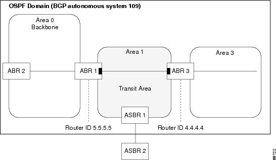

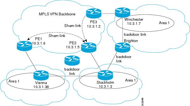
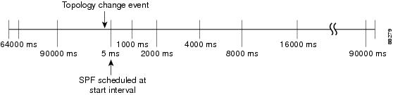
 Feedback