Cisco IC3000 Industrial Compute Gateway with Cisco Cyber Vision
The purpose of this document is to describe the procedures to successfully deploy the Cisco Cyber Vision Application on the IC3000.
This guide only discusses the interaction of the Cisco Cyber Vision Application on the IC3000. You must have a working knowledge of installation and deployment of the device, which can be found here:
Introduction
The IC3000 Industrial Compute Gateway (IC3000) is an edge computing platform which extends the cloud computing paradigm to the edge of the network. Instead of hosting applications in a remote data center, applications can now be hosted on the edge itself. Imagine, if we can host specific applications in the field close to the sensors, meters or the things. whatever may be the IOT use case, IC3000 serves the purpose by allowing us to deploy applications that need more cores and memory.
 Note |
Examples shown in this document use IP addresses that are from a lab environment and should not be used on a typical customer installation. |
Note |
The documentation set for this product strives to use bias-free language. For purposes of this documentation set, bias-free is defined as language that does not imply discrimination based on age, disability, gender, racial identity, ethnic identity, sexual orientation, socioeconomic status, and intersectionality. Exceptions may be present in the documentation due to language that is hardcoded in the user interfaces of the product software, language used based on RFP documentation, or language that is used by a referenced third-party product. |
Unboxing, Installing and Connecting to the IC3000 Device
Unboxing the IC3000
Complete details for the hardware installation of the product are covered in the IC3000 Hardware Configuration Guide. The following steps are a high level overview.
Installing the IC3000
- Review the general description of the unit in the Product Overview section of the hardware installation guide.
- Check the Equipment, Tools, and Connections section of the hardware installation guide to ensure you have everything you need for the installation.
- Review the procedures for Mounting, Grounding, Connecting to DC Power and Connecting to the IC3000 in the hardware installation guide.
- If you are installing the device in a Hazloc location, follow the printed instructions that came inside the box with the device.
- Power on the device.
Reset Button Options
The device can be returned to the original factory configuration by using the reset button. The reset button is a small button accessed through a pinhole located on the front of the device. For the location, see the IC3000 Hardware Configuration Guide .
The reset button options are:
- Press 10 to 15 seconds - Device is reloaded.
- Press 30 to 35 seconds - All user configurations (apps, network details) are removed and device is reloaded.
- Press 60 to 65 seconds - All user configurations are removed, all images are cleared except for the factory image, and the device is reloaded with the factory image.
Cisco Cyber Vision Sensor Application
The IC3000 can be ordered with the Cisco Cyber Vision sensor application, which will come pre-installed at manufacturing. The Cisco Cyber Vision sensor app allows traffic from a network to be captured in offline or online mode. This captured data can be viewed from Cisco Cyber Vision. For more information on how to explore the captured data and to navigate the Cisco Cyber Vision GUI please refer to the Cisco Cyber Vision GUI User Guide.
Note : The IC3000 contains 4 independent data capture ports (2 RJ45 copper ports & 2 SFP fiber ports) in SPAN mode, each of which can be connected to an on-site switch. The IC3000's data capture ports are to be connected to switches with SPAN configured.
Cyber Vision Sensor Application in Offline Mode
Cisco Cyber Vision sensor offline mode allows SPAN traffic to be captured from the 4 data ports onto a USB stick. This offline traffic can then be manually added to Cisco Cyber Vision, to provide visibility to the collected network traffic. To collect SPAN traffic onto a USB, and to manually add it to the CVC, follow the instructions below:
Procedure
| Step 1 |
Obtain an IC3000 with Cyber Vision sensor app pre-installed at manufacturing. |
||||
| Step 2 |
Plug a USB device in USB slot 1 of the IC3000.
|
||||
| Step 3 |
Power on the unit. |
||||
| Step 4 |
Connect any of the 4 data ports to on-site switches you wish to capture SPAN traffic. |
||||
| Step 5 |
Allow for the SPAN traffic to be collected for a day or two |
||||
| Step 6 |
Unplug the USB, connect it to a PC and verify that a .dat file is present.
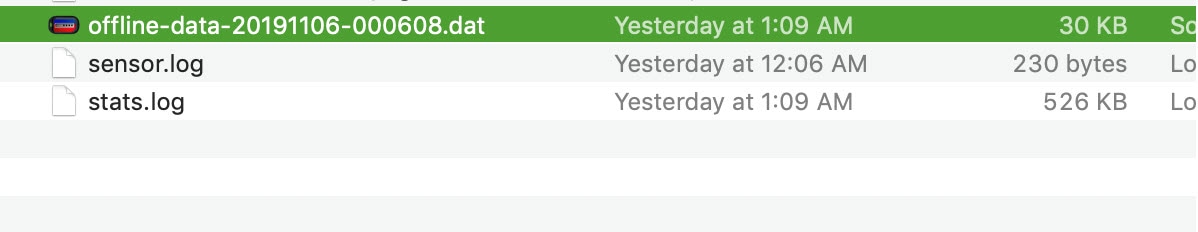 |
||||
| Step 7 |
Upload the .dat file to CVC by going to CVC home page > System Administration (cog icon on the top right) > Sensors > Import Offline File. 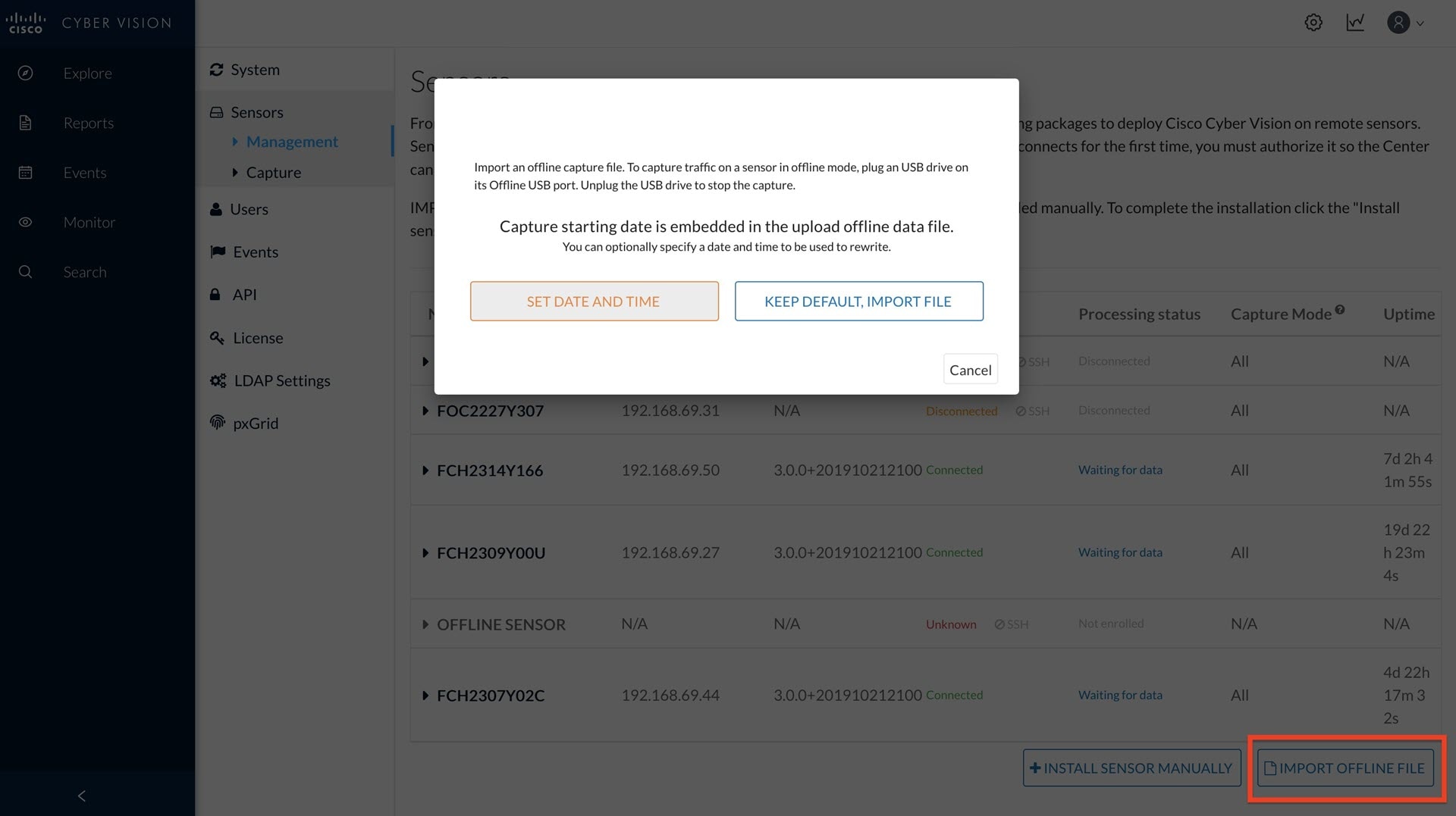 |
||||
| Step 8 |
If desired, you can manually change the date and time for the offline data file. |
Cyber Vision Sensor Application in Online Mode
Before you begin
Cyber Vision sensor online mode allows SPAN traffic to be sent continuously to the Cisco Cyber Vision's Collection Network for real-time visualization of industrial networks. To add a device and pass SPAN traffic to the Collection Network follow the instructions below:
Procedure
| Step 1 |
Login to Cisco Cyber Vision.  |
||
| Step 2 |
Go to the System administration tab by clicking the cog icon on the top right corner. See the following graphic. 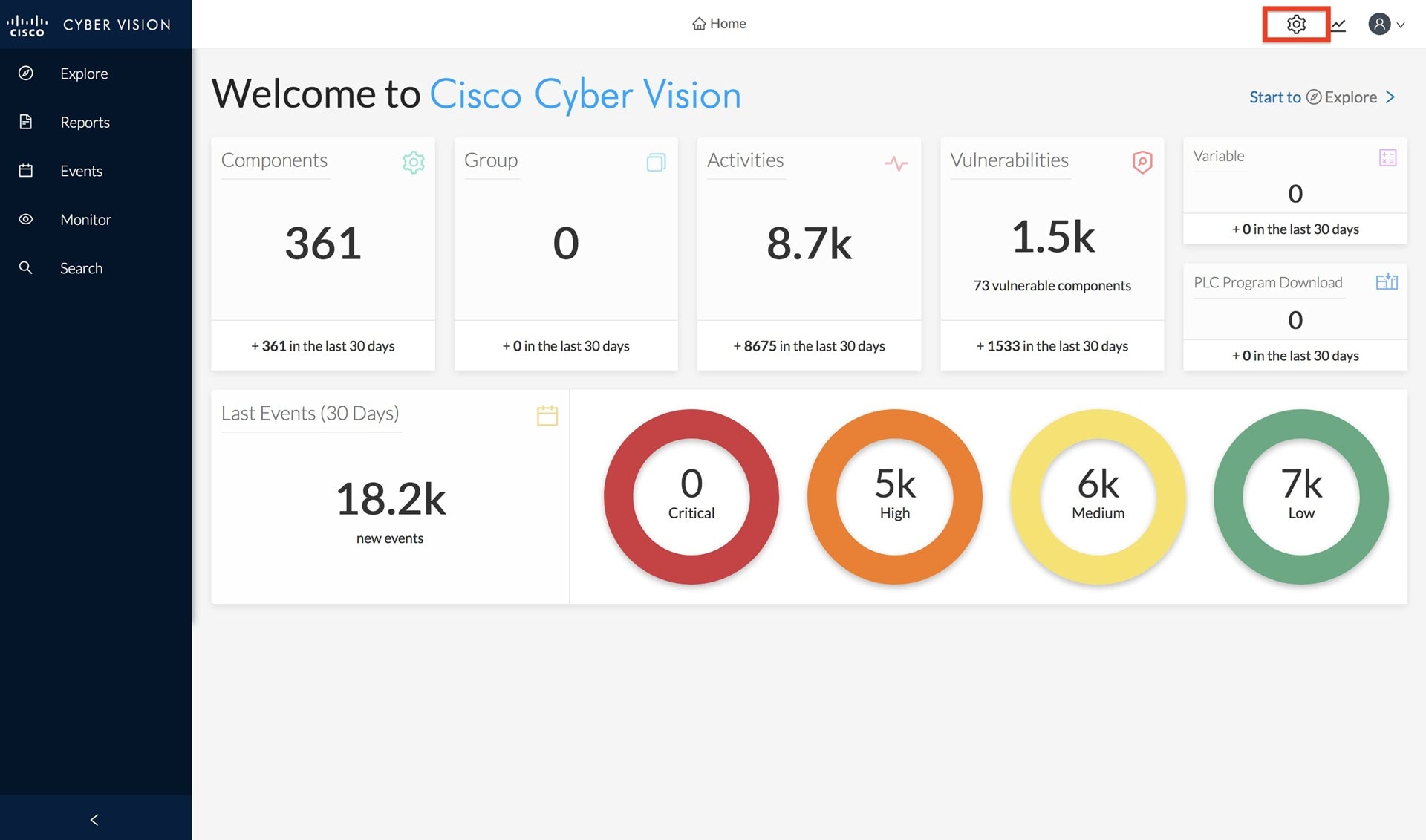 |
||
| Step 3 |
Click Install Sensor Manually by going to System administration > Sensors > Management > Install Sensor Manually. 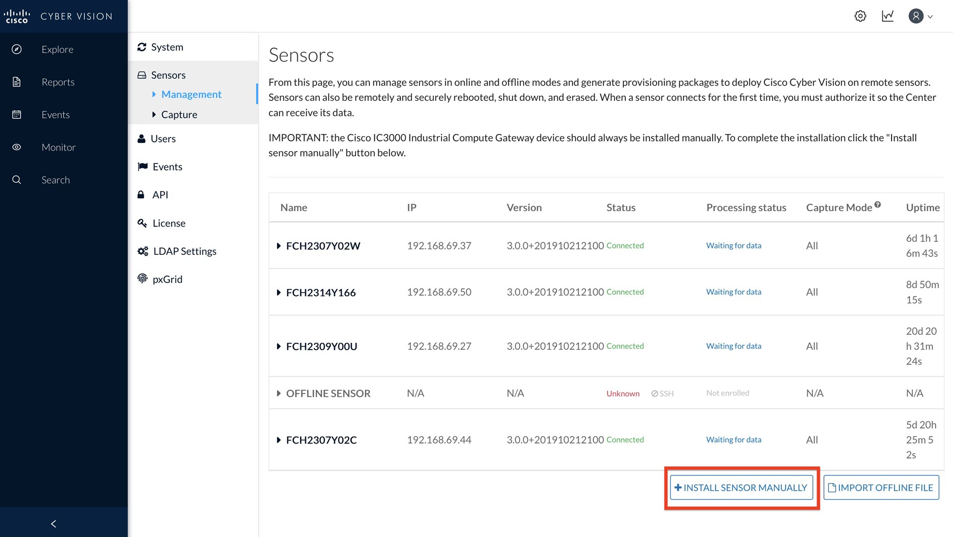 |
||
| Step 4 |
Select Cisco IC3000 as hardware model from the drop-down list. 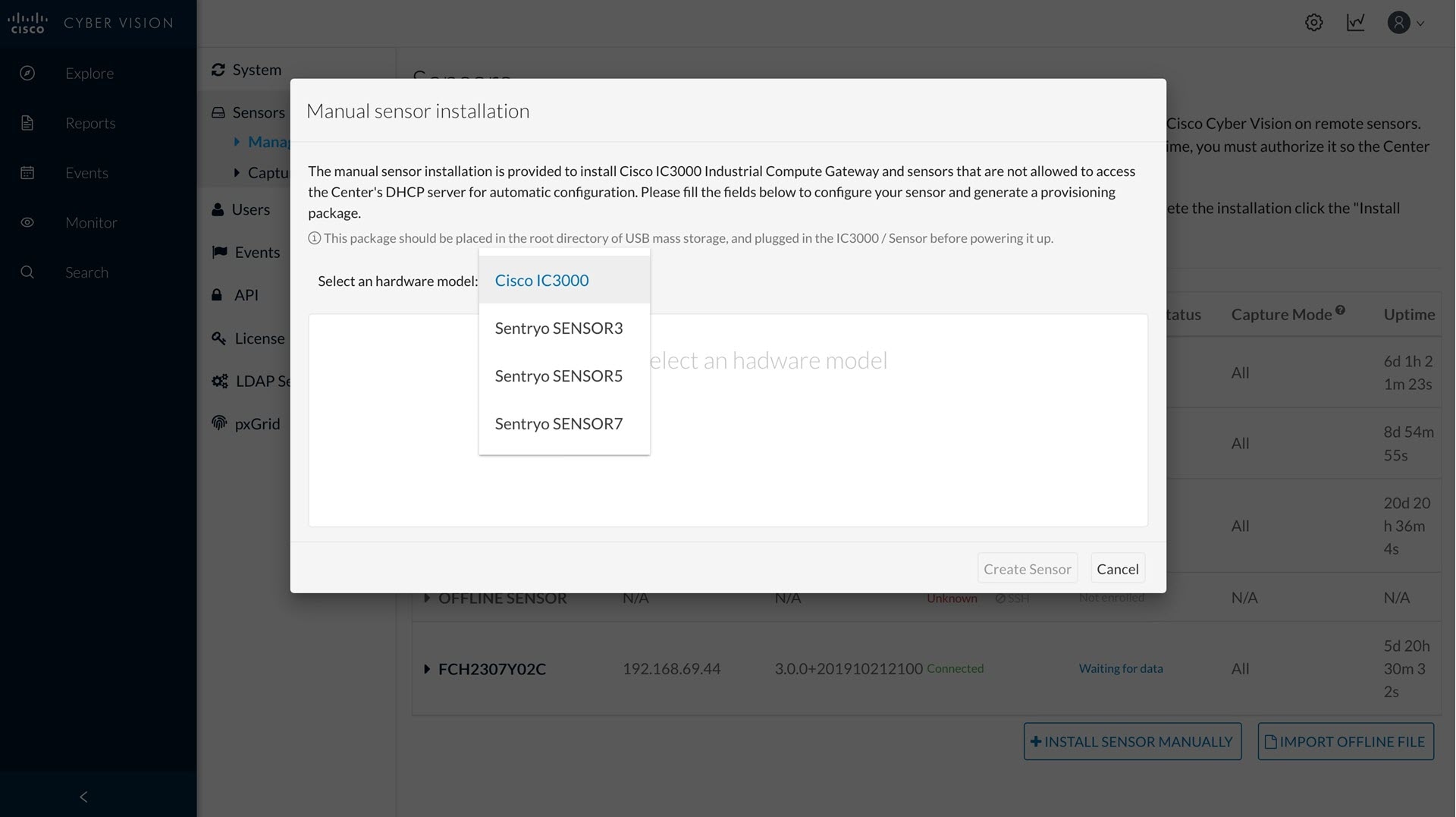 |
||
| Step 5 |
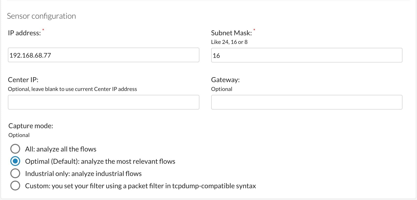
Fill out the Cisco IC3000 and Sensor configuration fields. Refer to the Filled Out Form and the Sensor Configuration Window. Caution : Make sure the network information entered is correct and will not result in a network conflict. Any mistake will require
a device reset to be performed, resulting in the device returning to factory defaults. This will lead to a complete deletion
of the inner system, which will require a special procedure to install the Cyber Vision Application manually via Local Manager.
Refer to Installing the Cyber Vision Sensor Application Using Local Manager after a Configuration Reset for more details if a reset must be performed on the IC3000 device. Refer to Reset Button Options for details.
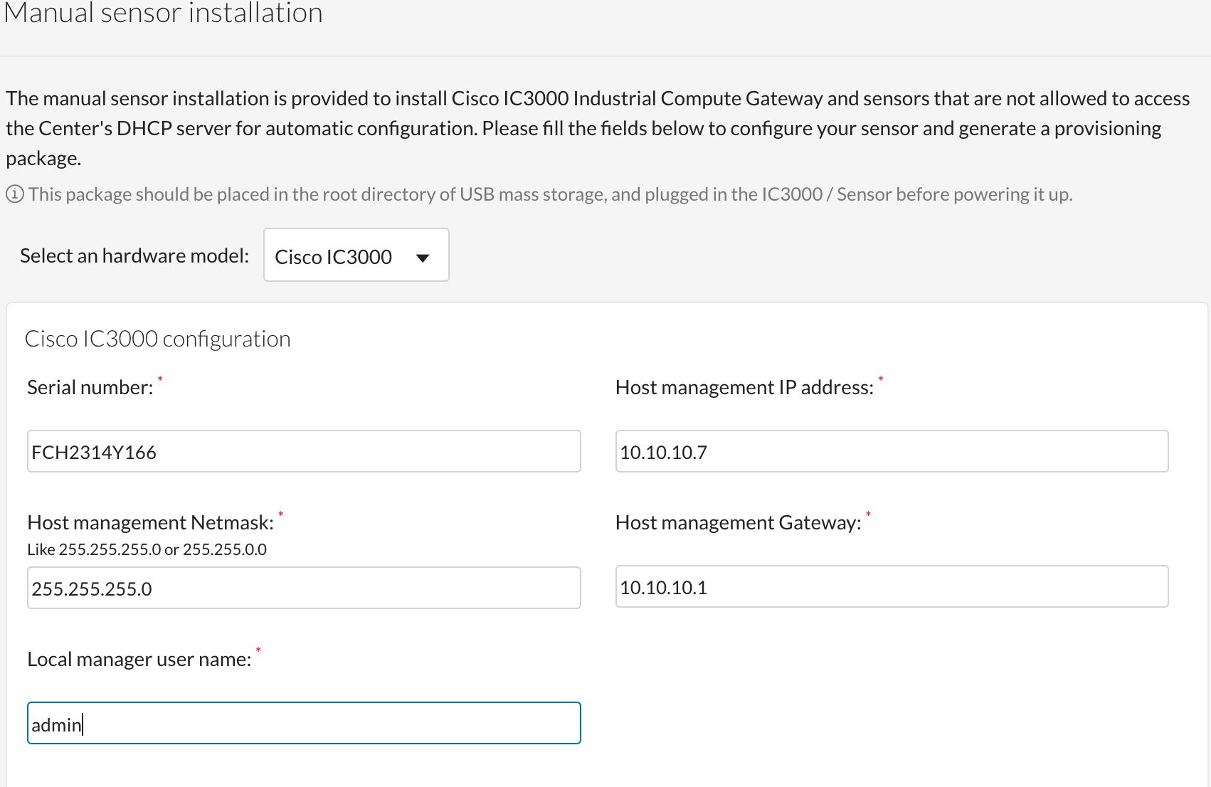 Note: The serial number for the IC3000 device can be found in the front view of the chassis. See Serial Number Location. The Local Manager default credentials are (username:admin/password:cisco123) for a device that was shipped from the factory. Enter “admin” for local manager username field. 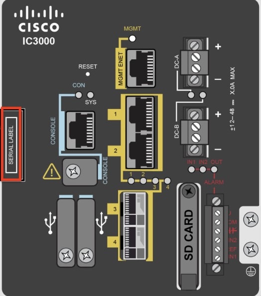
 |
||
| Step 6 |
Click Create Sensor. Once created, the sensor will appear in the sensor list with “New” as its status. Expand the sensor and click the Get Provisioning Package icon to download the sensor provisioning zip file. See the following graphic. 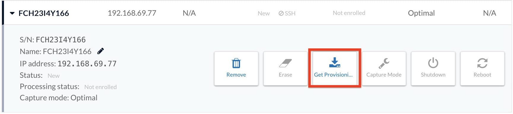 |
||
| Step 7 |
The Get Provisioning Package window opens. You are required to create a password. 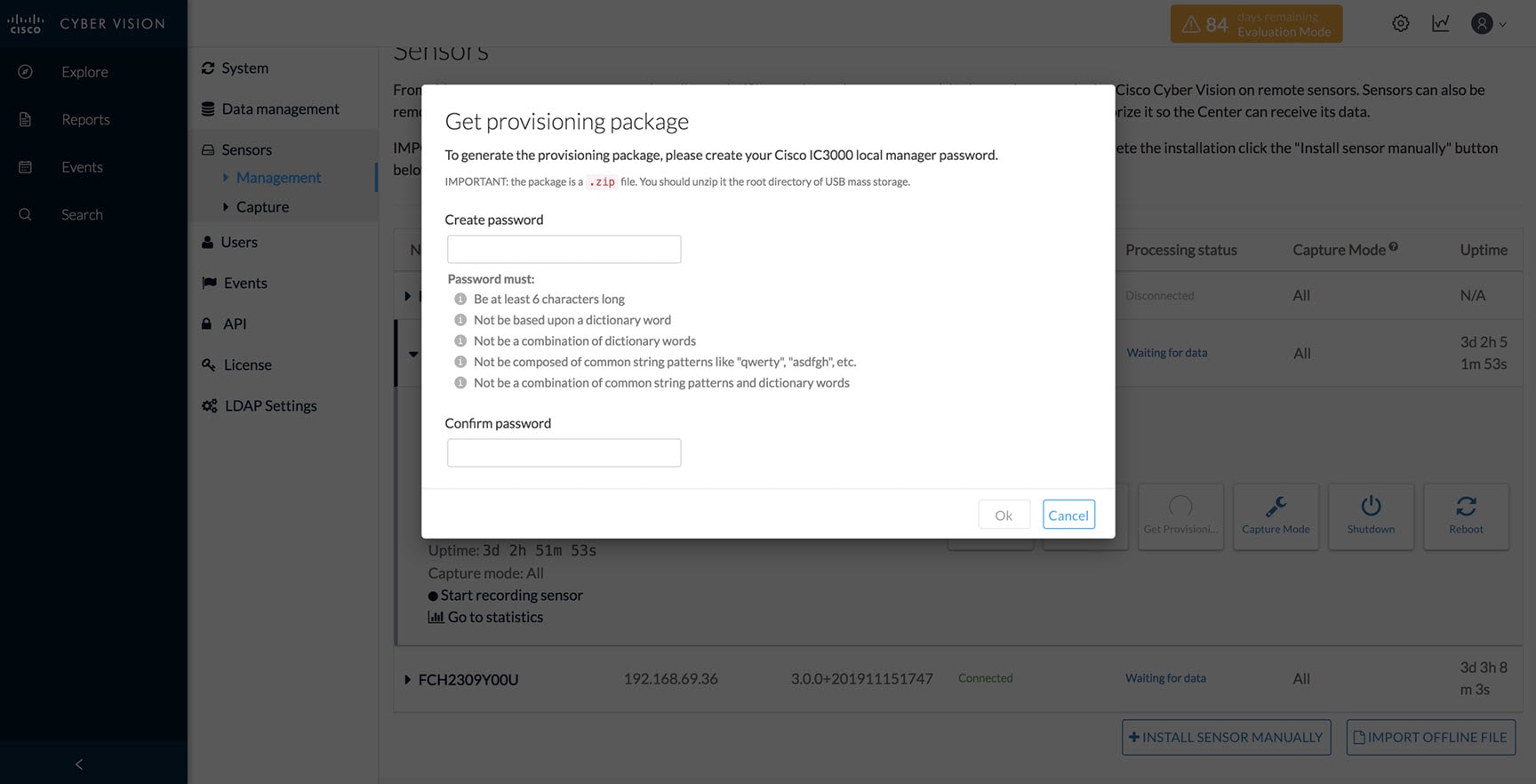 |
||
| Step 8 |
Enter a new password. The default password for the admin account will be replaced with this new password. In order to access the Local Manager, you will need to use this new password for the “admin" account. Make sure to keep this information stored and secured. Follow these password rules:
|
||
| Step 9 |
Click Ok. A serialNumber.zip file will be generated and downloaded on the laptop. Unzip the .zip file and copy the serialNumber folder to the root directory of the USB. 
|
||
| Step 10 |
Prepare your IC3000 by making sure you have proper power, console, and data connections available. |
||
| Step 11 |
Connect the USB stick you have prepared to USB slot 2, and plug the MGMT cable into the Collection Network. Also, connect any on-site switches that have SPAN configured to data ports 1 - 4 to pass SPAN traffic. See the following example setup. 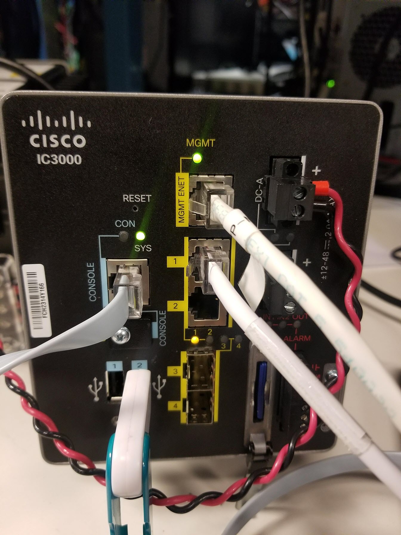 |
||
| Step 12 |
Power on the device. Once the device powers on the configurations on the USB are copied to the device and application. Cisco Cyber Vision sensor will register to Cisco Cyber Vision. Wait up to 5 min for the Cisco Cyber Vision sensor app to register. |
||
| Step 13 |
The Cyber Vision Sensor should show as “connected” under the Sensor status. The IC3000 status should quickly change to connected. The provisioning package has been installed successfully on the IC3000 and traffic starts to appear in Cisco Cyber Vision. 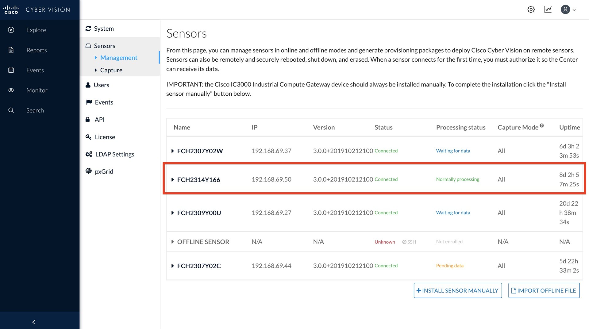 |
Installing the Cyber Vision Sensor Application Using Local Manager after a Configuration Reset
Performing a reset results in a factory default of the device. When this occurs, the Cisco Cyber Vision Sensor Application will be deleted and needs to be installed by using the LM. Refer to Reset Button Options for details.
To re-install the application, perform the following steps:
Procedure
| Step 1 |
Perform reset. Press the physical reset button on the IC3000 device for 30 - 35 seconds and make sure the MGMT cable is not connected. |
| Step 2 |
Follow steps 1- 8 from the Cyber Vision Sensor Application in Online Mode section. Also follow step 10, where you connect the USB stick in USB slot 2. Note: Make sure any old sensor installations using this IC3000 device have been erased. Go to Cisco Cyber Vision > System Administration > Sensors > Management to confirm the IC3000 serial number does not appear. |
| Step 3 |
Access the LM GUI using the IP address configured in the Host Management IP address field found in step 5 under the Cyber Vision Sensor Application in Online Mode section. Type the following URL in a web browser: https://< Host-MGMT-IP-Address >:8443 Make sure your MGMT cable has access to the Host Management Subnet. |
| Step 4 |
Login to the LM GUI using the credentials admin/newPassword, where new password is the password set in step 7 under the Cyber Vision Sensor Application in Online Mode section. |
| Step 5 |
Download the latest version of signed Cisco Cyber Vision’s Sensor Application from the Cisco download site. Go to Applications > Add New > Browse > OK. See the following graphic. 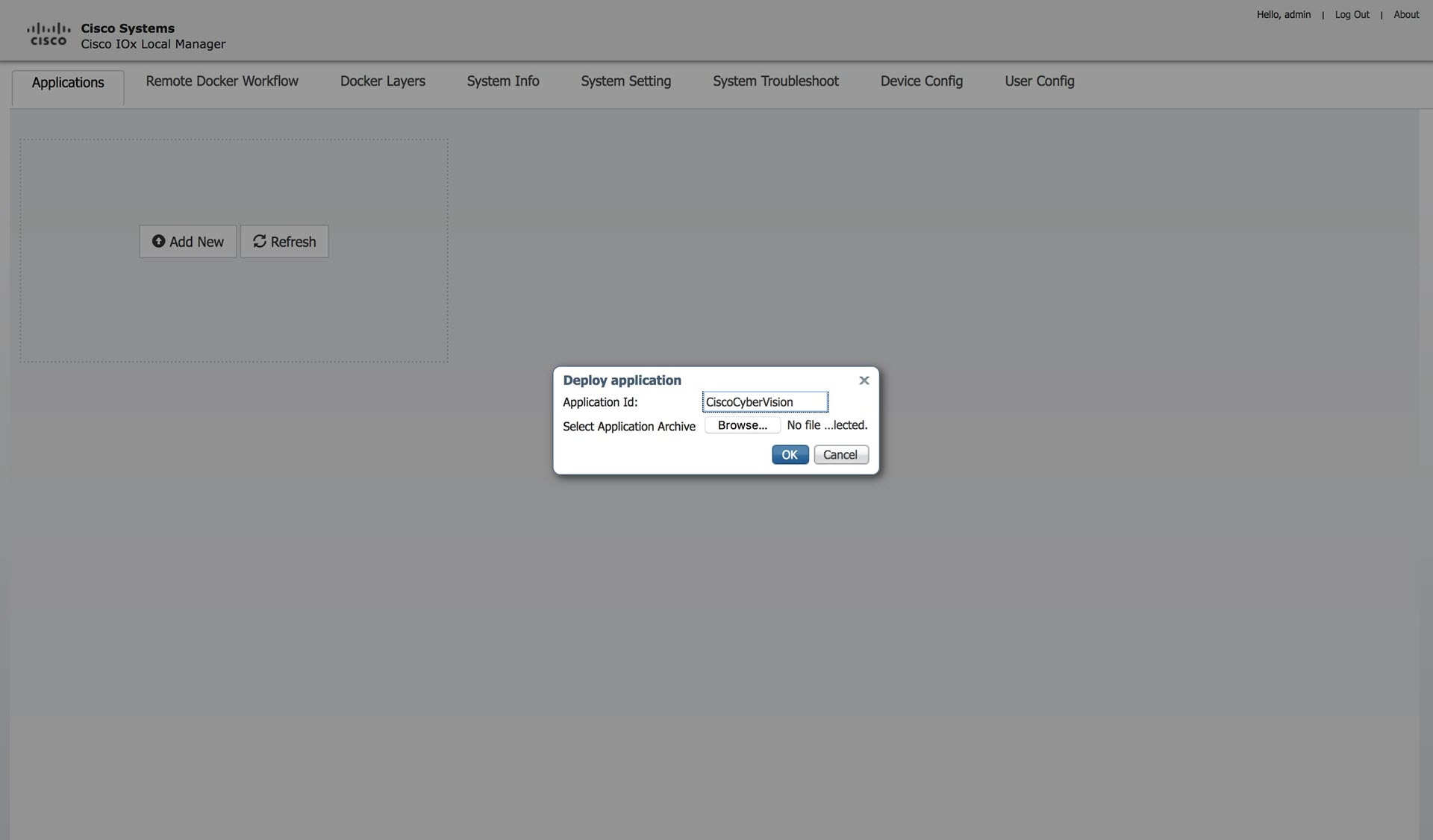 |
| Step 6 |
Press Activate on the Cisco Cyber Vision Sensor Application. 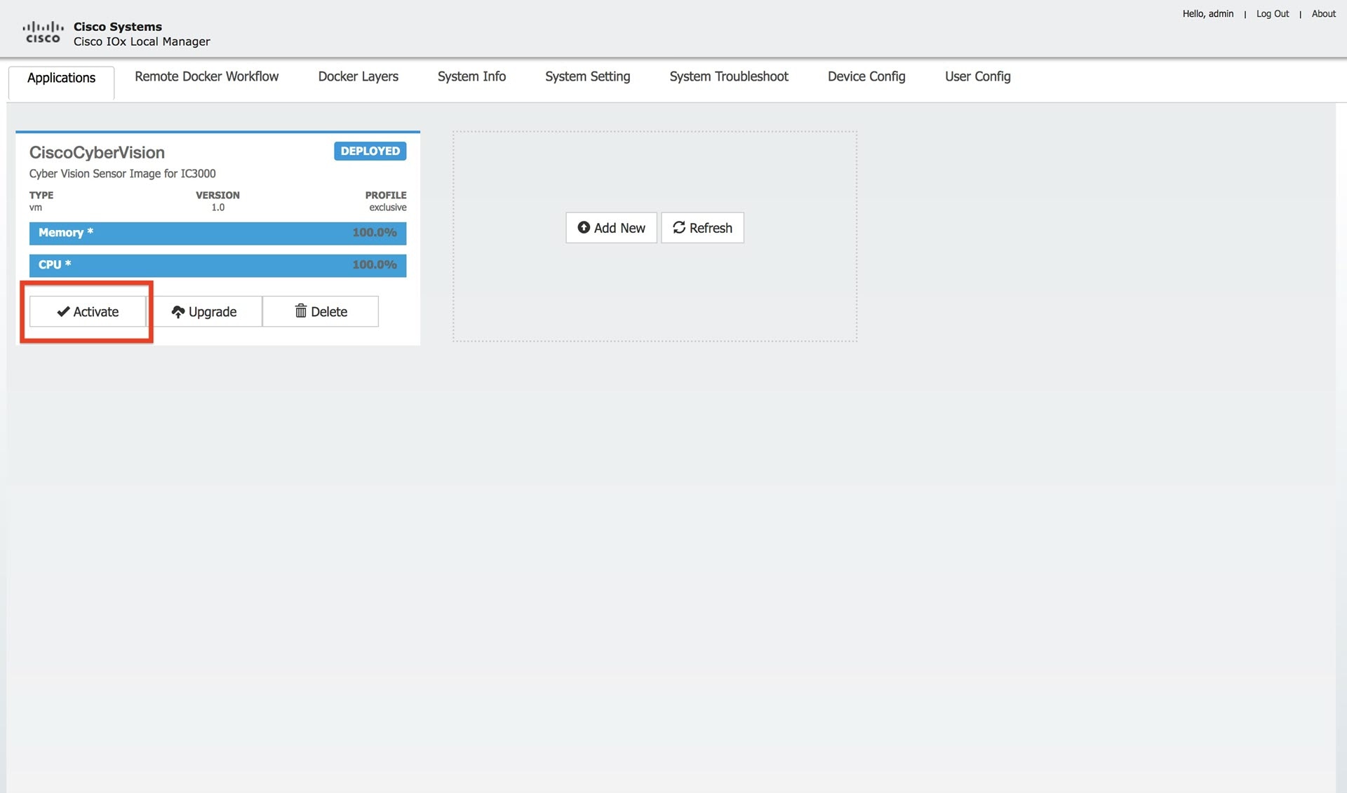 |
| Step 7 |
Add the Network Configurations. Click Edit on each interface. Each interface name should be mapped exactly in this format, eth0 > iox-bridge0, eth1 > int1, eth2 > int2, eth3 > int3, and eth4 > int4. 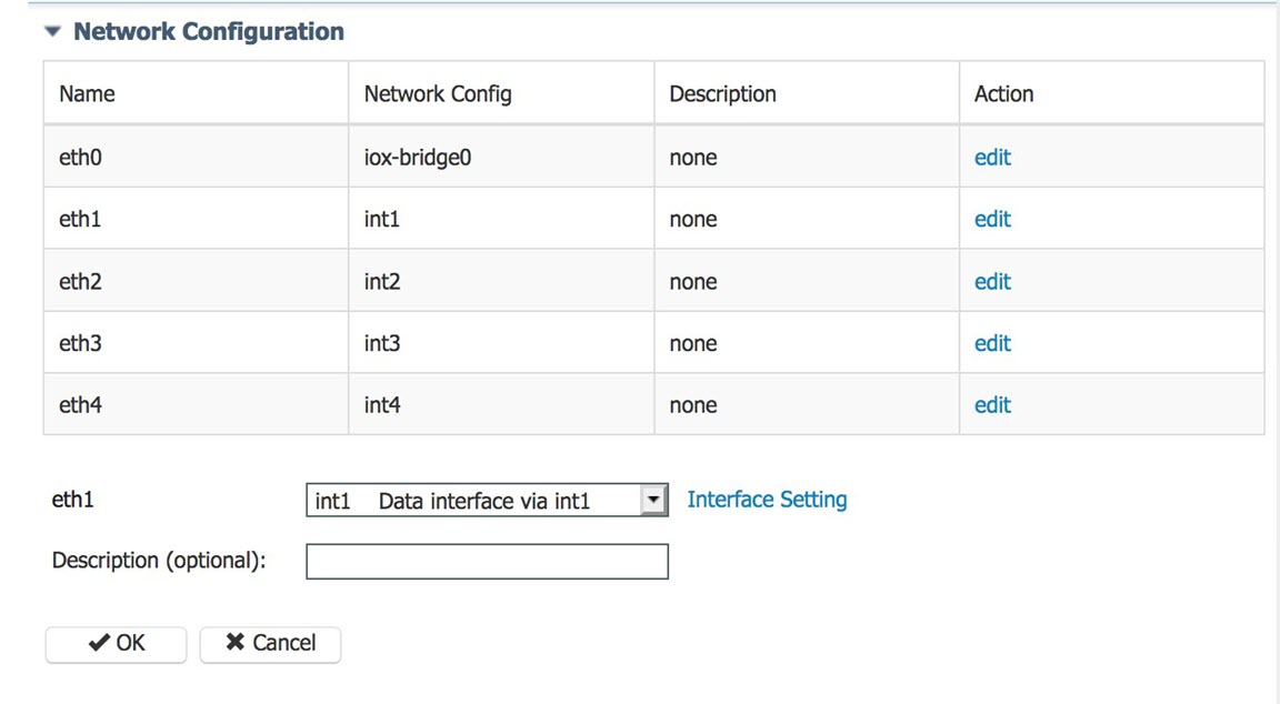 |
| Step 8 |
Next, eth1 - eth4 should be configured with Mirror mode Enabled. To enable Mirror mode, go to Edit > Interface Setting > Enable > OK for eth1 - eth4. 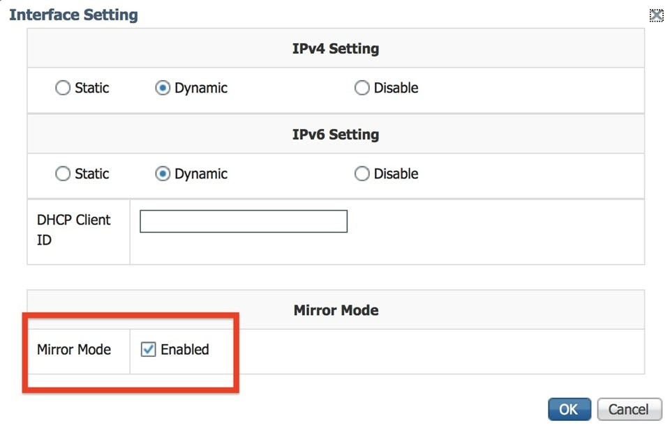 |
| Step 9 |
Add the Peripheral Configuration. Go to Peripheral Configuration > edit > Port:1usb1 > OK. 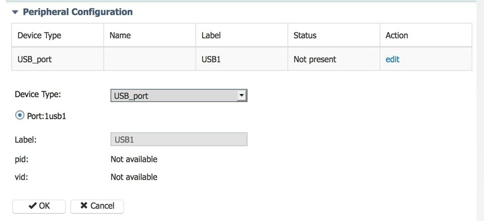 The following shows an example of the Added Peripheral Configuration. 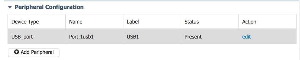 |
| Step 10 |
From the Cisco Cyber Vision Resources Tab, click Activate App to activate the application. 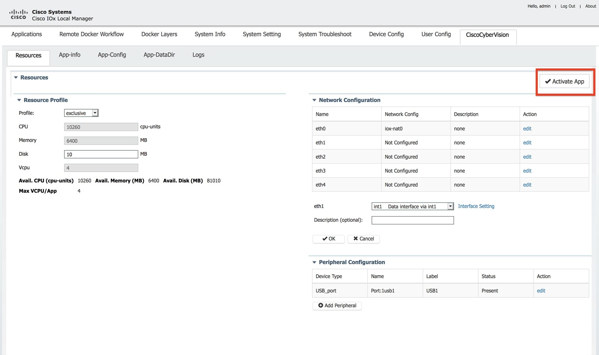 |
| Step 11 |
The next step is to start up the application. Go to Applications > Start App. 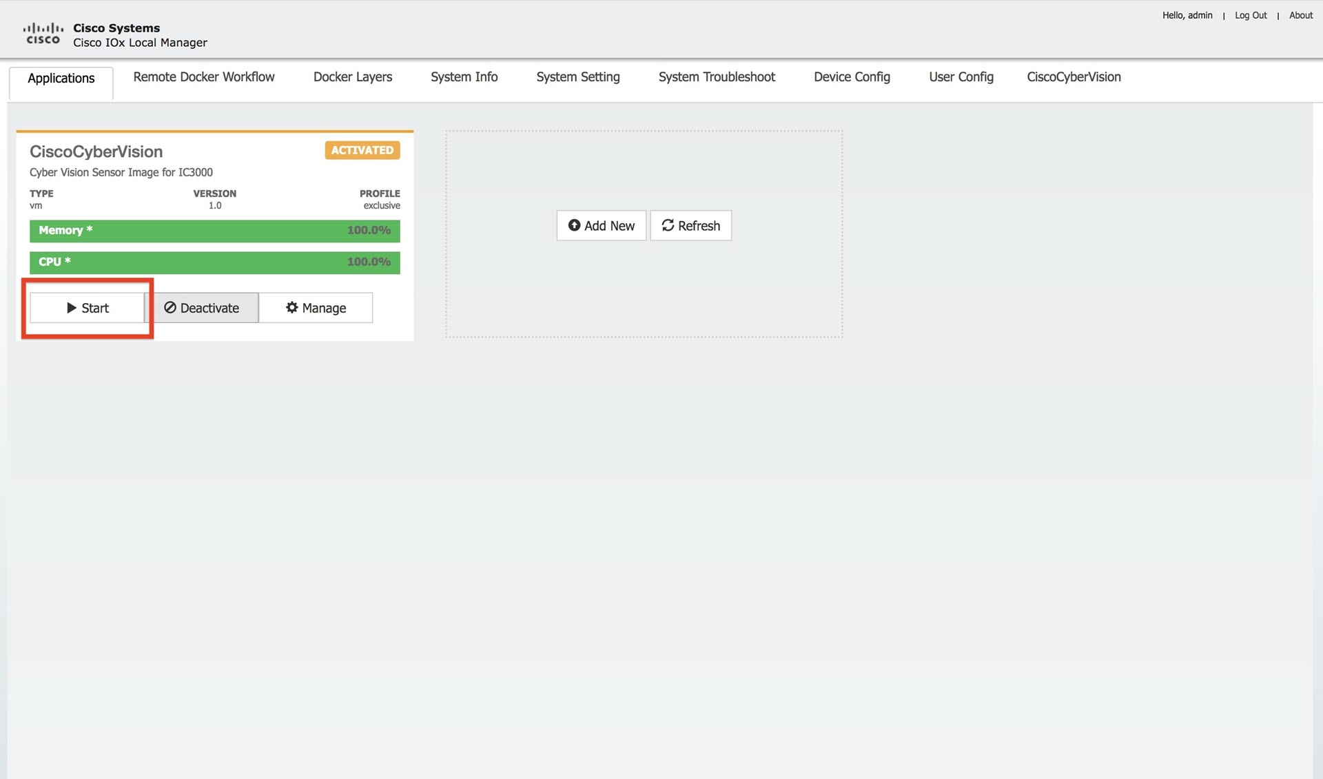 |
| Step 12 |
The application is now in a running state. |
| Step 13 |
Plug in the MGMT cable so that it has access to the Collection Network. The Cyber Vision sensor should show as “connected” under the Sensor status. |
| Step 14 |
Connect any on-site switches that have SPAN configured to data ports 1-4 to begin passing traffic to the Cisco Cyber Vision |
 Feedback