Cisco CSR1000V Series Cloud Services Router Deployment Guide for Amazon Web Services
Bias-Free Language
The documentation set for this product strives to use bias-free language. For the purposes of this documentation set, bias-free is defined as language that does not imply discrimination based on age, disability, gender, racial identity, ethnic identity, sexual orientation, socioeconomic status, and intersectionality. Exceptions may be present in the documentation due to language that is hardcoded in the user interfaces of the product software, language used based on RFP documentation, or language that is used by a referenced third-party product. Learn more about how Cisco is using Inclusive Language.
- Updated:
- April 24, 2017
Chapter: Configuring High Availability
Configuring High Availability
This section contains the following topics:
- Information about High Availability
- Error Messages for Amazon Web Services High Availability
- How to Configure High Availability
- Verifying High Availability
Information about High Availability
A method for deploying two Cisco CSR 1000v in a redundant pair with failover between them, is summarized below. See How to Configure High Availability for further details.
Configuring High Availability: Summary
-
Create an AWS Identity and Access Management (IAM) role to be able to access the AWS APIs.
-
Create an AWS VPC and launch each Cisco CSR1000v into the VPC with an Amazon EC2 IAM role.
-
(Cisco IOS XE Everest 16.6.1 or later) Enable the AX or SEC license, using BFD.
(Cisco IOS XE Everest 16.5.1 or earlier) Enable the AX license, using BFD.
-
Configure the CSRs to reach the internet and access EC2 AWS API servers.
-
Configure a GRE tunnel between the Cisco CSR 1000v's and enable Bi-directional Forwarding Detection (BFD) and a routing protocol (EIGRP or BGP) on the GRE tunnel between the routers, for peer failure detection.
-
Note the route table ID and network interface ID.
-
(Cisco IOS XE 3.16 or earlier) Monitor AWS HA errors such as BFD peer down events and specify the routing changes parameters: Route-table-id, Network-interface-id and CIDR range, by configuring each CSR 1000v with an Embedded Event Manager (EEM) applet. When a BFD peer down event is detected, the applet uses the AWS EC2 VPC API to modify the VPC route table to redirect traffic around the failure.

Note
For private subnets, do not use the IP address 10.0.3.0/24—this is used internally on the Cisco CSR 1000v for High Availability. The Cisco CSR 1000v needs to have public internet accessibility to make REST API calls that change the AWS route table. -
(Cisco IOS XE Denali16.3.1a or later) Monitor AWS HA errors such as BFD peer down events and specify the routing changes to Route-table-id, Network-interface-id and CIDR by configuring each CSR 1000v using the cloud provider aws command. When a BFD peer down event is detected, routing changes are made to the Route-table-id, Network-interface-id and CIDR range and the VPC route table is modified to redirect traffic around the failure.
Initial Topology
The initial topology and traffic flow are shown in the following figure, before performing the procedure: How to Configure High Availability.
Note | The procedure How to Configure High Availability shows how to configure high availability (VPC Gateway Redundancy) for a VPN gateway configuration in a single availability zone. For further examples, see the Deploying the Cisco Cloud Services Router 1000V Series in Amazon Web Services, Design and Implementation Guide . |
Ingress and egress traffic is initially forwarded through CSR-A.
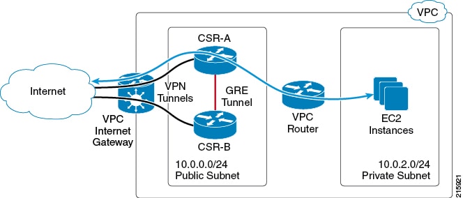
Each CSR has a primary Ethernet interface (GigabitEthernet1) that is assigned to the public subnet. The public subnet has a VPC route table with a default route target of the Internet gateway. Both CSR-A and CSR-B are launched in the same public subnet.
Each CSR also has a VPN tunnel to the Internet. These tunnels typically terminate at another VPN device located on the enterprise network or another VPC.
To support high availability , a GRE tunnel is configured between the local CSRs, which allows the CSRs to exchange BFD control packets that are used for peer failure detection.
The EC2 instances reside in a private subnet, Private Subnet (10.0.2.0/24), in the topology diagram. If the CSR is not directly connected to this private subnet, it is recommended to add a static route for the private subnet to each CSR. This static route points to the address of the VPC router on the public subnet. This address will always be the first usable address of a subnet. For example, the VPC router address for the subnet 10.0.0.0/24 will be 10.0.0.1.
EIGRP is used as the routing protocol, though other routing protocols could be used. The primary purpose of the routing protocol is to register as a BFD client. BFD requires at least one client protocol before it will initiate neighbor discovery. An additional benefit of the GRE tunnel and the routing protocol is that they can be used to establish a back-up path in case of VPN tunnel failures.
The EC2 private subnet has its own VPC route table. The default route for this subnet will have a target of the public subnet network interface (GigabitEthernet1) of one of the CSRs. Because the VPC route table only allows for one active target per route, only one CSR is in the egress traffic path for the subnet. Ingress traffic flow over the VPN tunnels is determined by the remote VPN devices. This means that CSR-B may be the active ingress path or that load sharing is performed between CSR-A and CSR-B.
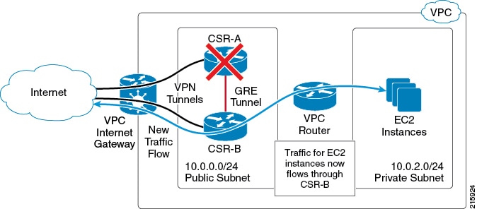
The next figure shows the new traffic flow that occurs after you have configured the steps shown in the procedure How to Configure High Availability and after a BFD peer down event. The modified VPC route table causes traffic to egress through CSR-B.
Error Messages for Amazon Web Services High Availability
Errors that may occur during route replacement (for Cisco IOS XE Denali 16.3.1a or later) are shown in the following table.
| Error Name | Message | Description |
|---|---|---|
|
BFDEVENT |
VXE BFD peer %i interface %s transitioned to down |
The BFD interface transitioned to down triggering a VXE Cloud HA event. |
|
BFDCONFIG |
VXE BFD peer %i configuration %s from %s |
The BFD configuration was removed while cloud HA is still configured. |
|
NOTCFGD |
VXE Cloud HA BFD is enabled, but %s node %u not fully configured |
The BFD state transitioned, but not all Cloud parameters were configured |
|
FAILED |
VXE Cloud HA BFD state transitioned, %s node %u event %s failed |
The BFD state transitioned, but failed to perform route replacement |
|
SUCCESS |
VXE Cloud HA BFD state transitioned, %s node %u event %s successful %VXE_CLOUD_HA-6-SUCCESS: VXE Cloud HA BFD state transitioned, AWS node 1 event replace route successful |
The BFD state transitioned, but failed to perform route replacement |
|
INIT |
VXE Cloud HA %s failed |
VXE Cloud HA initialization failure |
How to Configure High Availability
To configure High Availability (VPC Gateway Redundancy) using two Cisco CSR 1000v's, perform the following steps:
| Step 1 | Create an IAM role to access AWS APIs using IAM role temporary security credentials. The CSR 1000v's can then be launched with the privileges of this IAM role. Details of the IAM role creation are shown in “IAM Role Creation” in the “VPC Gateway Redundancy” section of the design guide; see: Deploying the Cisco Cloud Services Router 1000V Series in Amazon Web Services, Design and Implementation Guide. | ||||
| Step 2 | Create and configure a VPC based on the topology requirements and launch two CSR 1000v's (each with an IAM role) into the VPC. Then apply initial configurations, including VPN tunnels. For more information on deployment steps and CSR 1000v configuration, refer to other sections within this document and the following white paper (PDF): Setting up DMVPN on the CSR in AWS Cloud. | ||||
| Step 3 | (Cisco IOS XE Everest 16.5.x or earlier) Enable the AX license, using BFD in this case, with the license
boot
level
ax command. Save the configuration and reboot. Use the show license command to inspect the license status. For example, Example: CSR-A(config)# license boot level security % use 'write' command to make license boot config take effect on next boot CSR-A(config)# end CSR-A# write memory Building configuration... [OK] CSR-A# reboot | ||||
| Step 4 | (Cisco IOS XE Everest 16.6.x or later) Enable the Security package, with the license
boot
level
security command. Save the configuration and reboot. Use the show license command to inspect the license status. For example, Example: CSR-A(config)# license boot level security % use 'write' command to make license boot config take effect on next boot CSR-A(config)# end CSR-A# write memory Building configuration... [OK] CSR-A# reboot | ||||
| Step 5 | Configure the CSRs to reach the internet and access EC2 AWS API servers. The default route table on the public subnet of CSRs needs a route for the internet gateway and needs to be able to reach the EC2 AWS API servers to modify the routes. The CSR interface on the public subnet, Gigabit Ethernet 1, should not have a configuration that blocks http traffic or contain access list rules that may block the access of EC2 AWS API servers. | ||||
| Step 6 | Configure the GRE tunnel, using EIGRP. Configure the GRE tunnel using the Elastic IPs of the CSR 1000v's (recommended to avoid DHCP lease renewal issues detecting false failures.) The BFD values can be configured to be more aggressive than those shown in the following example, if faster convergence is required. However, this can lead to BFD peer down events during intermittent connectivity. The values in the following example will detect peer failure within 1.5 seconds, and this setup has been shown to be stable in an AWS VPC environment. There is a variable delay of about a few seconds between the time when the AWS API command is executed and when the VPC routing table changes go into effect. Example: Example: interface Tunnel1 ip address 172.17.1.1 255.255.255.252 bfd interval 500 min_rx 500 multiplier 3 tunnel source GigabitEthernet1 tunnel destination 54.215.144.53 /* Elastic IP of the peer CSR */ ! router eigrp 1 bfd interface Tunnel1 network 172.17.0.0 passive-interface GigabitEthernet1 ! | ||||
| Step 7 | In the AWS console, look in the left nav bar, under VPC Dashboard > "Virtual Private Cloud" > Route Tables, and make a note of the Route Table ID for each Cisco CSR 1000v.
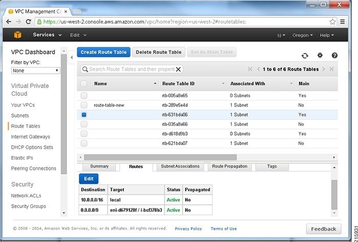 | ||||
| Step 8 | Look in the EC2 Dashboard, in the left nav bar, under "Instances"and select the Name of an instance in the window on the right. A dialog box shows the details of the Network Interface; for example, titled "Network Interface eth0". Make a note of the Interface ID.
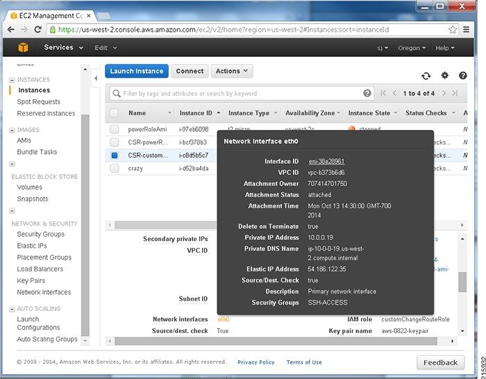 (The Route Table ID and Interface ID will be needed in the following steps.) | ||||
| Step 9 | (Cisco IOS XE 3.16 or earlier. For Cisco IOS XE Denali 16.3.1a or later, go to step 10.)
Configure the container virtual-service csr_mgmt ip shared host-interface GigabitEthernet1 activate | ||||
| Step 10 | (Cisco IOS XE 3.16 or earlier.)
Monitor BFD peer down or similar AWS HA events using an EEM applet. Define the following EEM environment variables: RTB—the route table ID for the private subnet VPC route table CIDR—destination address for the route to be updated in the route table.
ENI—the network interface ID of the CSR 1000v gigabit interface to which traffic is routed REGION—the AWS region of CSR 1000v and DNS IP address Configure the EEM applet in a similar way to that shown in the following example. Example: In this example, the four EEM environment variables (RTB, ENI, CIDR and REGION) are set for the applet replace-route2(These variables are later used by the action 1.0 publish-event command.)
event manager environment RTB rtb-631bda06
event manager environment ENI eni-d679128f
event manager environment CIDR 0.0.0.0/0
event manager environment REGION us-west-2/10.0.0.2
event manager applet replace-route2
event syslog pattern "\(Tunnel1\) is down: BFD peer down notified"
Example: The following command uses the previously defined EEM environment variables, which are to be used in the event of an AWS HA error. action 1.0 publish-event sub-system 55 type 55 arg1 $RTB arg2 $CIDR arg3 $ENI arg4 $REGION After an AWS HA error occurs, routing changes are made to the VPC's route-table-id, network-interface-id and CIDR according to the values specified in the environment variables. | ||||
| Step 11 | (Cisco IOS XE Denali 16.3.1a or later). Use the cloud
provider
aws command.
Monitor BFD peer down events by configuring each CSR 1000v using the cloud provider aws command specified below. Use the command to define the routing changes to (VPC) Route-table-id, Network-interface-id and CIDR after an AWS HA error such as BFD peer down, is detected.
CSR-RTR-A(config)# redundancy CSR-RTR-A(config-red)# cloud provider [aws | azure] node-id # bfd peer ipaddr # route-table table-name # cidr ip ipaddr/prefix # eni elastic-network-intf-name # region region-name
Example: CSR-RTR-A(config)# redundancy CSR-RTR-A(config-red)# cloud provider aws 1 # bfd peer 172.17.1.2 # route-table rtb-30535b54 # cidr ip 172.33.0.0/16 # eni eni-3029b64f # region us-west-2
Next, go to Verifying High Availability. |
Verifying High Availability
Verify that the BFD and EIGRP relationships are established and normal on both peers. This example shows the local peer on Tunnel 33, and also the remote peer on Tunnel 98.
Router# show bfd neighbors
IPv4 Sessions
NeighAddr                              LD/RD         RH/RS     State     Int
172.17.1.2                           4097/4097       Up        Up        Tu1
Router# show ip eigrp neighbors
EIGRP-IPv4 Neighbors for AS(1)
H   Address                 Interface              Hold Uptime   SRTT   RTO  Q  Seq
                                                   (sec)         (ms)       Cnt Num
0   172.17.1.2              Tu1                      11 02:02:31   19  1470  0  7
For Cisco IOS XE 16.3.1a or later, the following two additional verification commands are available:
show redundancy cloud provider [aws | azure] node-id
debug redundancy cloud [all | trace | detail | error]
Example:
show redundancy cloud provider aws 1
Cloud HA: work_in_progress=TRUE
Provider : AWS node 1
        State : running
        BFD peer     = 172.18.1.2
        BFD intf     = Tunnel5
        route-table  = rtb-30535b54
        cidr         = 172.33.0.0/16
        eni          = eni-4527b83a
        region       = us-west-2
 Feedback